High Conductance Flow Meter Installation and Operations Manual
←
→
Page content transcription
If your browser does not render page correctly, please read the page content below
High Conductance Flow Meter
                      Installation and Operations Manual

                               10808 Fallstone Rd Suite 350
                                  Houston, TX 77099 USA
                                 Toll Free: 1-800-896-7108
                          Phone: 281-564-5100 FAX: 281-564-5200

                                 E-mail: admin@dynamax.com
                          International Email: exports@dynamax.com
                                  Website: www.dynamax.com

Revision: FEBRUARY 2021                                              1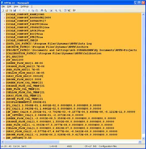
Table of Contents

1.0 Features and What is New in HCFM3.......................................................................................4-6
      1.1   High Conductance Flow Meter (HCFM) Form & Function.............................................7-8
      1.2   Personal Computer Requirements ...................................................................................8
      1.3   Pressured Bottle Requirements........................................................................................8
      1.4   Unpacking.........................................................................................................................9
      1.5   What to Keep!...................................................................................................................9

2.0 Quick Start Guide.........................................................................................................................10

3.0 Application and Theory of Operation..................................................................................11-13
     3.1    Why use the HCFM?.......................................................................................................11
     3.2    Transient Measurements of Conductance of Roots....................................................11-13
     3.3    Quasi-steady State Measurement of Hydraulic Resistance, RQS..................................13

4.0     HCFM Installation Guide.....................................................................................................14-26

5.0 Setup for the HCFM.................................................................................................................27-38
      5.1   Operational Imerperative.................................................................................................27
      5.2   Valve Setting for Preparing the HCFM for Service.......................................................27
      5.3 Pressurizing the HCFM....................................................................................................27
		5.3.1 Tips for Setting the Pressure Regulator.............................................................................................28
		                 5.3.2 Preparing the Compressed Air Supply System for use with HCFM...................................................29
 5.4 Adding Degassed Water to the HCFM..............................................................................30
		5.4.1 Making Degassed Water/ Preventing Algae Buildup Inside the HCFM.....................................31
		                 5.4.2 Priming a Totally Empty Captive Air Tank (CAT)........................................................................32-33
		                 5.4.3 Adding water to a Partly Empty Captive Air Tank (CAT)............................................................33-34
 5.5 Elimination Air from the HCFM......................................................................................34-35
		5.5.1 Purging Air from the Water Filter................................................................................................35-36
		                 5.5.2 Removing Air Trapped in the 8-way Manifold..............................................................................36
		                 5.5.3 Removing Microscopic Air Bubbles from the Pressure Transducers........................................37
		                 5.5.4 Removing Microscopic Air Bubbles from the HCFM-Bleeding..................................................37
         5.6      Storing the HCFM............................................................................................................38

6.0 Software Operation.................................................................................................................39-55
      6.1   System Connections.......................................................................................................39
      6.2   HCFM Operation Guide...................................................................................................40
      6.3   Set-Zero dP-Transient Conductance Preparation......................................................40-41
      6.4   Transient Measurement of Conductance.....................................................................42-45
                    6.4.1. Measurement of the Transient.....................................................................................................42
                    6.4.2. Regression of the Transient, Current Data.................................................................................45
         6.5       Regression of Transient, Saved Data (.trn) Files........................................................46-47
         6.6      Introduction QSS Quasi-Steady State.........................................................................48-52
                     6.6.1. Getting Started...............................................................................................................................48
         6.7       Graphics Operation....................................................................................................53-54

Revision: FEBRUARY 2021                                                                                                                                                   2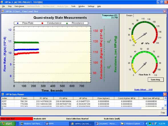
Table of Contents

7.0 Raw Data for K, and Temperature Corrections.....................................................................55-57
      7.1 Temperature Correction with Built in Sensor...............................................................................55
      7.2 CorrectionsatTestTemperature.................................................................................................55
      7.3 Raw DataTables, Project Data...................................................................................................56
      7.4 K25-ConductanceatStandardTemperature..............................................................................56-57

8.0 Obtaining Good Data, and Data Presentation.....................................................................58-61
     8.1 Wound Response (Plugging of Stems)..........................................................................58
     8.2 Air evenly distributed in the wood of a large branch......................................................58
     8.3 Cautions when measuring small flows/conductance or larger resistances...................58
     8.4 Air Bubbles...................................................................................................................59-61

9.0 Connecting the HCFM to the Roots and Shoots................................................................62-67

10. Disconnecting the HCFM ......................................................................................................68
      10.1 Valve Settings for moving the HCFM...........................................................................68
      10.2 Disconnecting and Moving the HCFM..........................................................................68

11. Maintaining the HCFM.............................................................................................................69
     11.1 Changing the Water Filter.............................................................................................69

12. Calibration of the HCFM..........................................................................................................70-77

Appendix I Parts List.....................................................................................................................78

Appendix II Bill of Materials.........................................................................................................79

Appendix III Trouble Shooting and FAQ.....................................................................................80-81

Appendix IV Reference List.........................................................................................................82-83

Appendix V Glossary....................................................................................................................84-86

Revision: FEBRUARY 2021                                                                                                                   3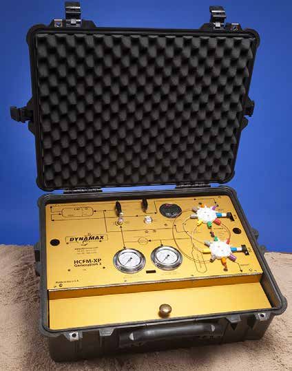
1. Features and What is New in HCFM GEN3
Here is a new and updated HCFM product based on the Dynamax history of 15 years of producing this leading plant characterization
instrument.

•   New High Res Generation 3 HCFM
•   Reading Sensors direct in parts per million
•   NIST calibration standard feature
•   Instant data regression, and auto-saver aged results
•   USB powered data acquisition
•   New High speed sensor conversion module
•   Flow ranges increased by 50%
•   Vista, XP, supported
•   Windows 7, 8, 10 compatible
•   Upgrade packages available to previous HCFM systems,
    with new factory calibration

The HCFM-Gen3 measures how water movement relates to
the pressure differences required to draw water from the soil
or through a plant.

The hydraulic conductivity relationship is a quantitative
analysis for roots and stems. The measurement is performed in the field, where in-situ root system can be measured in its
natural environment.

In most cases, the analysis of a sample root or shoot is completed in as little as 10 minutes. HCFM-Gen3 measures the
major components of the hydraulic conductance in the soil-plant-atmosphere continuum (reference #70.) The hydraulic
architecture of a whole shoot or of a single leaf can be represented by a resistance diagram similar to the electronic circuit
shown. One can measure the values of the individual hydraulic resistances, then compute the pattern of water flow and
water potentials in the resistance network. Each hydraulic resistance element (R) equals the pressure difference driving flow
through the element divided by the resulting flow (F) (reference #82).

All data sets are saved within the Project Manager framework file structure. Transient results as well as QSS flow meter data
are saved for easy viewing in with Excel, including the computed conductance, temperature and averaged results.

Advantages

In the HCFM method, the resistance of the root and shoot are measured separately by pressure perfusion and added
together. The HCFM will help plant physiologists and agronomists look forward to those seasonal studies of root and shoot
progression, water potential, or soil treatment effects.

Revision: FEBRUARY 2021                                                                                                       4
Designed for Two Types of Numerical Analysis

The first analysis is an in-situ transient analysis of hydraulic conductance. HCFM measures the flow as the water pressure
increases while flowing into the root or shoot. The software then intelligently calculates the slope of the increased flow
and pressure. That slope is the hydraulic conductance. The second analysis is a quasi-steady state flow meter, (QSS),
providing a constant pressure and flow into the sample. This derives the flow pressure and conductance in a steady state
environment, and computes conductance, as well as hydraulic resistance.

Software

The HCFM comes with menu driven software that is easy to use and straightforward in it’s approach. The software also
includes diagnostics and calibration modes to assure the user of correct readings. All data is saved to the PC hard drive for
later analysis by HCFM or graphing packages.

What’s New

• 1000 times more resolution with a highly advanced analog
  processing board (24 bit A/D)

• Highest analog resolution on the market provided

• USB powered Analog to digital circuit – Batteries not required

• Single USB high-speed data stream – No more parallel port
  to add

• Powerful instant regressions, with chart saving and printing

• All regression and streaming data are saved automatically
  – No more hand written data

• Individually calibrated pressure ranges on two pressure
sensors with traceable N.I.S.T. precision

• Accuracy calibrated on all pressure readings ±0.1%,typically r2=.99

• Temperature Monitoring added with automatic Standard Temp adjustments to 25° C

• Completely revised Windows .NET user application
  package

• Installation compatibility across all Microsoft OS,
   Vista, Windows 7, 8, 10, XP, NT

• Application Platform Basis on .NET, the workhorse
  platform for Microsoft Supported developers
  writing in C#

• New Calibrations, Improved Specifications

Revision: FEBRUARY 2021                                                                                                    5
Specifications for HCFM

Stem Ranges
1 mm to 36 mm diameters

Flow Rates
0.01 to 350 grams/hr in 5 overlapping ranges

Conductance
7.7E-08 to 3.5E-04 Kg s-1 MPa-1

Electronic A/D
24-bit resolution dual Analog / Digital converters

Analog/Digital
One reading every two seconds

Data Interface
USB, USB powered

Dimensions
22” x 19” x 9” (61 x 48 x 23 cm)

Weight
33 lb (15 kg)

Capacity
24 oz. Degassed Water

Maximum Pressure
90 psi (620 kPa)

Air Gas Tank
6 cu. ft. (170 liter) with CGA-580 Valve & Connector

Revision: FEBRUARY 2021                                6
• Sensor zero set provided with linear and 2nd order polynomial regressions removes sensor and board drift between
  data sets

• Improved overlap on conductance ranges by 50% Differential pressure calibrated to 180 kPa

• Sensor Nonlinearity removal by unique software adjustment, 1-4th order effects removed

• Conductance and resistance results at the reading temperature are adjusted according to the calibration
  temperature

• Temperature adjustments are performed automatically to deliver results at 25° C

• Direct flow calibration increased to 15 points from 12.

• 50% increase in the flow range / pressure difference for all 6 flow ranges

New Graphic Analysis

High-resolution result graphics with dynamic zoom, detail zoom, auto scale. Steady state flow meter: results translated to

•   Resistance
•   Conductance (new)
•   Flow (new)
•   Ten Point Average Option

Large, easy to read pressure gauges are digitally painted on screen.

• Color coded ranges automatically defined
• Audible and graphic warnings provided to prevent
  over pressure or out of range readings
• Flow gauge readout in % of full scale as well as a
  detailed 2D chart in Kg*s-1
• Easy to read raw data display of all
  important parameters
• Set-up and control options in one menu
• Protected calibration mode
• All changes to initialization automatically
  backed up

Dynamic – Transient Conductance (K) with rapid conductance
regression display.

• Instant regression, with chart view, save and printing
   options
• Re-analysis of saved data
• Two types of data exclusion: Min/Max, and Pick points
   to ignore

New Project Manager organization folders automatically organize your data by date. Data sets are saved to the designated
folder, with comments. Calibration files, initialization and set-up files are saved separately from data.

Interactive Help Options, Documentation built into application are coming soon.

Revision: FEBRUARY 2021                                                                                                      7
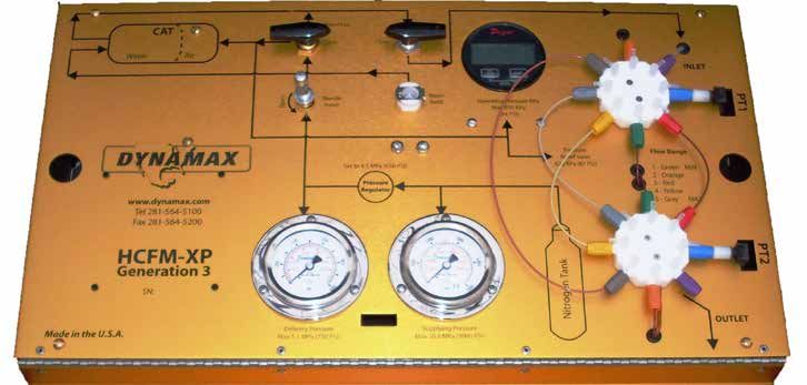
1.1 High Conductance Flow Meter (HCFM) Form & Function
The HCFM is shown schematically in Figure 1. It is an apparatus designed to perfuse water into an object while rapidly
changing the delivery pressure and simultaneously measuring flow. This is referred as a transient conductance measurement.
The slope of flow plotted versus pressure equals the hydraulic conductance of the object. The object can be an excised shoot
or excised root system or capillary tube (for test purposes). The HCFM may also measure quasi-steady state conductance,
i.e., under conditions where flow and applied pressure are approximately constant with time.

                                                           W
                                                           A

                                                                   CT

                                                                Figure 1
                                            Schematic of High Conductance Flow Meter (HCFM)

The rapid change in water pressure is achieved using a pressure regulator (R), a needle valve (NV), and a captive air tank
(CAT). A pressure regulator (R) delivers compressed air from the compressed air tank (CAT). The pressure regulator keeps
the compressed air at a steady pressure of 4 to 5 MPa (580-725 PSI) through a needle valve (NV).

The NV is connected to the air-chamber (A) of a captive air tank (CAT). A rubber diaphragm separates the air from water
(W) in the CAT. The NV is adjusted to permit a rate of airflow to pressurize the air volume at a rate of 3 to 7 kPa s-1 (approx.
1-PSI s-1). The volumes of air and water are approximately equal in the CAT. The CAT can be pressurized or depressurized
by turning the 3-way ball valve (AV).

A pressure release valve (PR) prevents accidental over-pressurization. The pressure release valve is set to vent air when
the pressure exceeds about 0.6 MPa (87 PSI). Since the pressure in (A) never exceeds 0.6 MPa, and the air supply is 4.2
MPa (609 PSI), the pressure drop across the NV is approximately constant. This allows the rate of pressurization in the
water to be approximately linear with time.

Pressurized water flows from the CAT to the 8-Way Inlet manifold (8WI) through a 9 mm Inside Diameter (ID) nylon-
reinforced Tygon tubing.  At a distance of 0.3 m from the CAT the water passes through a 0.1 micron water filter, then the
diameter of the tubing is reduced to 3 mm Outside Diameter (OD) plastic tube; the plastic tubing is connected to the input
side of the 8WI. The 8WI is shown schematically in Figure 1. The 8WI is an 8-Way HPLC valve of octagonal geometry with
8-tubes emerging from a common point in the center and each tube terminated by a valve.

On the inlet side, the 3 mm OD (1.5 mm ID) tube from the CAT is connected to one of the 8 valves (purple connector on
the HCFM). A pressure transducer (PT1) is connected to another valve (blue connector on the HCFM). On the outlet side
another pressure transducer (PT2) is connected to 8WI (blue connector) as well as the 3 mm OD (1.5mm ID) outlet tube
(purple connector). This leaves 6 pairs of valves available between each 8WI and 8-Way Outlet (8WO) for connection of
narrow-bore capillary tubes (CT).

The capillary tubes are 1.5 mm OD HPLC tubing 0.16 to 1.5 m in length. The HPLC CTs have internal diameters from
0.12 to 0.5 mm. During a measurement, one CT is selected by opening the inlet and outlet valves of the corresponding
manifold (8WI and 8WO). The corresponding CT valves for the unused capillary tubes must be closed. Water flow across
the selected CT causes a differential pressure (dP) drop (dP = P1 -P2) measured with PT1 and PT2, respectively.

Revision: FEBRUARY 2021                                                                                                       8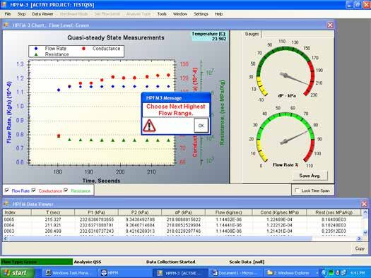
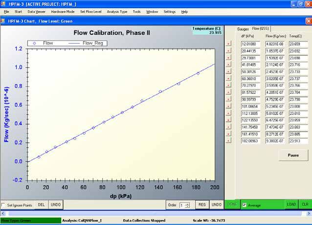
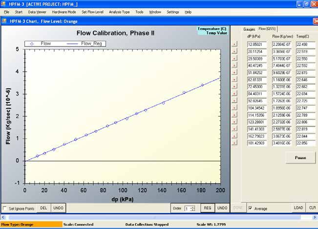
Calibration curves were established relating flow, F, to dP values in the range of 0 to 180 kPa. HPLC capillary tubes up to
0.25 mm ID have linear calibration curves. HPLC capillary tubes 0.3 mm ID or larger are nonlinear because of the transition
from laminar to turbulent flow. All calibrations are performed by Dynamax.

The pressure measurements are made with model PX26-100GV solid-state strain-gauge transducers. The output of the
pressure transducers is logged using a custom-designed, dual channel A/D circuit with 12 bits plus sign accuracy. The
HCFM is supplied with Windows software for controlling the A/D circuits, logging data, and for preliminary data analysis.

The Flow Outlet side of the 8-Way manifold is connected by a 6-foot (1.8 m) length of water-filled 1.5 mm ID Teflon FEP
“Clear” tubing to a compression fitting (CF). This FEP tubing permits connection to the larger size plant or root base with 19-
50 mm fittings (HPCC19-35 and HPCC34-50).  Additional  (1 mm ID) HPLC “Natural” (light tan) tubing is supplied for use on
smaller sized roots and shoots with 1-20 mm fittings (HPCC 1-4, HPCC 4-10 and HPCC 10-20). We also supply 0.127 mm
ID ‘RED’ tubing, which is used to assist air bubble removal in the system AND to use for test measurement. This red tube
has the conductance of a small seedling with about 100 to 200 cm2 of leaf area. A range of compression fittings is supplied
to permit connection to stems ranging from 1 to 50 mmOD.

1.2     Personal Computer Requirements

The program that controls the High Conductance Flow Meter Gen3 is installed under a program file directory, to run the
software use an IBM compatible computer with an 800 x 600 pixel screen or better. The computer must be running on
32-bit Windows XP/2000/Vista, 64-bit WindowsXP/2000/Vista, or Windows 7, 8, 10. Two USB ports are required, one to
communicate with the usb-2404UT analog converters, and one for the USB “Keylock” USB dongle, provided for access to
each customer’s unique HCFM.

The software is supplied on the included flash drive and can be installed by running the setup.exe file. The install shield
Wizard will install the program in:

C:\Program files\Dynamax\HPFM.ini

There are five distinct parts to software installation, allowing customers to leverage software created independently, by
Microsoft, Measurement Computing, USB software experts and Dynamax Inc. Installation is covered in detail in Section
4.

        1. Install latest Microsoft. NET, if required, the Visual c. frameworks.
        2. Install the Dynamax, HCFM.exe, and the graphics drivers, calibration files, initialization files, and example data.
        3. Install Keylock, the security key to enforce Dynamax copyright protection.
        4. Install measurement computing InstaCal, the analog conversion utility incorporated into our product.
        5. Install USB device drivers, that access and control the USB data converters.

See Section 4, “HCFM Installation Guide” for the steps to install the HCFM software:

Dynamax supplies the HCFM with a professional factory calibration traceable to NVLAP calibrate scales and pressure
transducers. The calibration file is included on the software disk under the file name HCFM.ini.

1.3     Pressured Bottle Requirements

Dynamax ships the HCFM-C models with a compressed air tank, regulator, and hose for connection to the
HCFM. This tank can be pressured to 1850 pounds per square inch (PSI) or 12,755 Kilo-Pascal’s (kPa). It has
a volume of 6 cubic feet (Cu. Ft.) or 170 liters. The regulator allows control of pressures up to 3000 PSI or
20,685 kPa. This air tank or bottle cannot be shipped filled, so you will need to fill the bottle (air tank) with a dry
compressed gas. Economically, two gases are best: Nitrogen or dried compressed air. The compressed air tank
can be filled by University physical plants (they can assist you) or distributors such as Air Liquide, Linde, or BOC Gases.
The setup for running a transitory test requires enough pressure (600 PSI or 4,100 kPa) to deliver a constant flow of gas
to the HCFM. The pressure regulator requires about 700 PSI in the tank to deliver 600 PSI to the HCFM. It must deliver
the gas without “choking” and causing a reducing flow of gas over the time period of the test.

Revision: FEBRUARY 2021                                                                                                      9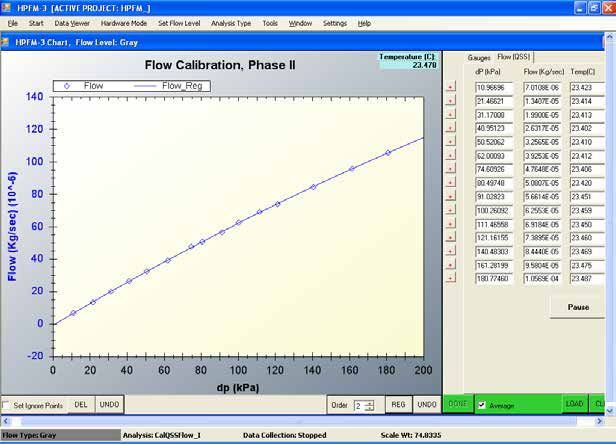
WARNING!
    The compressed air tank must have at least 700 PSI (4,800 kPa) to run a transient pressure
                                             test.

1.4      Unpacking

The HCFM is supplied as a complete unit. No assembly is required. However, there are several accessories that are
packaged with the system such as:

•   O-rings
•   Compression caps
•   Connection and bleeding hoses
•   Compression Couplings
•   Communications Cable
•   Manual and Software

It is recommended that you take a few minutes to check off and confirm all of these components were received. A detailed
Parts and Packing List is below.

1.5      What to Keep!

                                               NOTE:
                     When unpacking, do not discard the box and packing material.

Dynamax ships the HCFM in a box with material on all six sides, his makes the shipping box the perfect box for you to
keep and ship your HCFM internationally, across the U.S., or back to Dynamax for an annual calibration. Also keep the
Lists of Parts, the software, and the accessories that came with the HCFM. The list will come in handy when reordering
parts for the HCFM. The software should be kept as a backup in case of PC failure such as hard drive corruption. The
accessories should be kept in the lid of the HCFM since they will be needed to use the HCFM on a daily basis.

                                                HCFM-XP Gen 3 Packing List
             HCFM-XP        Hydraulic Conductance Flow Meter with software CD, calibration documentation
               1401         Small O-Rings (10 Pack)
               1402         Large O-Rings (10 Pack)
               1535         .005'ID X 1/16" OD 5ft. red peek tubing
             PM-2040        .042" (1mm), HPLC 5ft Nat. peek tubing
          EW-06406-62       1/16" ID X 1/8" OD 6ft Teflon rigid tubing
         HPCC 1-4 1001 1-4mm Two Way Connector
        HPCC 4-10 1008 4-10mm Universal Connector
             RSW502         3/8" Cone Washer for 8-10mm Range
            HPCC10-20       10-20mm Compression Coupling with rings
            HPCC19-35       19-35mm Compression Coupling with rings
               # 6/12       # 6/12 Rubber Stoppers (Drilled 6)
                # 10        # 10 Rubber Stoppers (Drilled 9)
                 G4         Silicone Coupling Grease with MSDS
              Keylock       USB keylock with Lanyard
      Plastic Compression Nuts (2)
      Spare 9v Alkaline Battery
      Refill bottle
      3cc & 30cc Syringes, blunt end 1 3/8 and 7/8 needles, Blade
      Algaecide 60 with Safety Sheet

Revision: FEBRUARY 2021                                                                                              10
2. Quick Start Guide
This section is designed to provide a recipe style reference guide to present the basic steps you should follow to assist the
new user to begin using the HCFM. The manual then provides more detailed instruction on how to complete each step.
1. Fill the Air Supply Tank with Compressed Air or Nitrogen – Section 5.0
2. Prepare 2 L of degassed, de-ionized water – Section 5.4.1
3. Prime the Captive Air Tank of the HCFM with degassed deionized water – Section 5.4
4. Eliminate all air from the HCFM by purging air from the CAT and Tygon supply tubing, through the purge valve and
water filter purge caps. Then bleed the system with the small Red capillary tube over night to remove any microscopic
air bubbles that may have remained in the CAT or the 8-Way valve manifolds. – Section 5.5
5. Insert the security lock provided with each HCFM. Connect the HCFM to a PC via the computer’s USB Port and the
communication port on the HCFM with the communications cable. – Section 6.0
6. Check the LED on the HCFM and launch the program by clicking on the HCFM3 icon. Listen for a beep, and notice the
green LED blinking on the USB-2404UI Analog Module. Open a project file folder to collect data, or reopen an old
project file – Section 6.2
7. Set the Zero Flow Volts to zero the transducers before taking measurements. This must be performed each day
before beginning measurements to ensure accuracy – Section 6.3
8. Select the plant that you will be working with and measure the stem size – Section 9.0
9. Cut the sample plants stem and install the Pressure couplings – Section 9.0 Use (1 mm ID) HPLC “Natural” (light tan)
tubing with fittings 1-20 mm (HPCC 1-4, HPCC 4-10 and HPCC 10-20) and (1.5 mm ID) Teflon HPLC “Clear”
tubing with fittings 19-50 mm (HPCC 19-35 and HPCC 34-50)
10. Determine the correct flow range to use for your selected sample. If you do not have the correct flow range set, your
measurements will be over-scale and you may think the system is not functioning properly. – Section 6.4
11. For roots begin your experiment with a Transient Measurement function, as this is the quickest method for gathering
hydraulic conductance data and will minimize any plugging effects caused by the plants natural healing process.
For large stems you may need other methods – Section 6.5
12. After collecting transient flow data you can immediately perform a Regression analysis of the data using the HCFM
software to determine the Hydraulic Conductance of the sample plant. The temperature of the test is automatically
recorded and a correction will convert raw reading to the test temperature KC, and K25- converted to standard
temperature – Section 6.5.2
13. As your understanding of the system develops, begin using the Quasi-Steady State Flow Meter function. By
measuring total resistance of the sample you can determine the contribution that individual components make to the
overall hydraulic conductance of the plant. – Section 6.6
14. Before beginning an intensive experiment be sure to understand all the necessary tips and cautions required to
measure hydraulic conductance successfully – Section 8.0
Revision: FEBRUARY 2021 113. Application and Theory of Operation
3.1 Why use the HCFM?
The High Conductance Flow Meter has several uses in the analysis of root/shoot studies. Some examples of the uses of
the HCFM are:
• Root conductance in the lab or field
• Conductance of shoots and petioles with or without leaves
• Root Stress Analysis on trees or crops
• Modeling root to shoot communications
• Transpiration models
• Root water status studies
• Absolute varietal comparison statistics
• Mycorrhizae nutrient/water enhancement studies
• Soil to root conductance statistics
• Crop conductance studies
3.2 Transient Measurements Conductance of Roots
Experience has shown that during flow measurements on roots, flow frequently declines even when the applied pressure,
P2, is constant. Reasons for this include:
1. During perfusion, solutes accumulate in the stele by reverse osmosis causing a continual decrease in driving
force on water movement.
2. Natural wound responses induced when the shoot is excised cause plugging of the xylem within the first few
centimeters of the wound causing a continual decline in K.
Readers are referred to (Tyree et al. 1993 and Tyree et al. 1995) for details. Consequently, the HCFM has been designed
to measure K quickly before the above effects become serious enough to influence K. Doing rapid measurement raises
other sources of error that need to be addressed.
The rate of water flow into roots, F, will exceed the rate of passage through the roots, Fh, if the root is initially dehydrated
since some of the water will remain behind to re-hydrate cells. But F will exceed Fh even in fully hydrated roots
because pressurization will cause elastic swelling of the roots or the HCFM. F will also exceed Fh because of
compression of any air-bubbles that might be present in the wood, the stem interface, or the HCFM. So F will be given
by:
NOTE:
It is essential that users of the HCFM are aware of potential sources of error and know of
ways to minimize such errors
F = Fh + Fe + Fb (5)
Where: Fe is the flow associated with elastic swelling and Fb is the flow to compress air bubbles (when present).
If the flow through the object measured is a linear function of applied pressure difference between the outlet of the
HCFM and atmospheric pressure, we can express Fh as:
Fh = K P2 (6)
Where: P2 is the outlet pressure relative to atmospheric pressure. The volume of the tubing, connectors, and object
measured will increase with P2. If the volume increase is elastic and linear with pressure, then the volume of the
system, V, will be given by:
Revision: FEBRUARY 2021 12V = Vo + P2/e (7)
Where: Vo is the initial volume of the system at P2 = 0 and e is the bulk modulus of elasticity. The time derivative of
Equation (7) gives the flow to cause the elastic volume change:
Fe = dV/dt = (1/e) dP2/dt (8)
If air bubbles are present anywhere in the system, they will be compressed according to the ideal gas law as the
pressure of the fluid around the bubble increases. If Vb is the volume of a bubble at absolute gas pressure Pb then
the ideal gas law gives:
PbVb = nRT = PiVi (9)
Where: n is the number of moles of gas in the bubble, R is the gas constant, T is the Kelvin temperature, and Pi is the
initial gas pressure and Vi is the initial volume. If we write Equation (9) as Vb = ViPi/Pb and take the derivative with
time we get the rate of volume change of the bubble:
dVb/dt = -(ViPi/Pb2)dPb/dt (10)
The negative sign of the derivative indicates that Vb decreases with increasing Pb. The flow of water to compress the
gas volume is the negative of Equation (10) so we have:
Fb = -dVb/dt = (ViPi/Pb2)dPb/dt (11)
In the case where all of the air bubbles are near the outlet side of the flow meter, we can equate Pb to P2 + Pi. Pi is
the initial absolute pressure of the bubble when P2 = 0. Pi approximately equals 0.1 MPa. The barometric pressure
will determine the Pi. There will also be a small contribution by the surface tension of the air-water interface to bubble
compression. In the special case where the air bubbles are near the outlet of the flow meter, the dynamic flow will be
given by substituting Equations (6, 8 and 11) into (5):
F = K P2 + (1/e) dP2/dt + ViPi/(P2 + 0.1)2 dP2/dt (12)
During normal operation of the HCFM, the inlet pressure P1 increases linearly with time, and after a short time delay
this causes P2 to increase linearly with time to make dP2/dt equal to a constant. This permits easier interpretation of
results because it makes the elastic contribution a constant offset to Fh. The contribution of the three terms in Equation
(12) is illustrated in Figure 2 for the case where P2 increases linearly with time from time = 0 (Figure 2 (A)).
The component flows (Fh, Fe, and Fb) and total flows are shown in the below.
It is not possible, in practice, to make P2 increase linearly with time from time 0. This is because an extra conductance
A C
P2 P1
→
→
P2
Pressure
Pressure
Time → Time →
B F
Fh D F
Fh
→
→
Flow
Flow
Fe Fe
Fb
Fb
PT2 → PT2 →
Figure 2
Transient Measurements Conductance of Roots
Revision: FEBRUARY 2021 13equal to the conductance of the capillary tubes of the HCFM (KCT) is interposed between the pressure transducers that measure P1 and P2 (see Figure 1). When the full set of equations is derived (not shown) a short time lag is predicted before P2 increases linearly with time (see Figure 2 (C)). The resulting component and total flows are shown in Figure 2 (D). Air bubbles generally can be avoided within the flow meter tubing and apparatus, but sometimes air is in the vessels and/or intercellular air spaces in the base of roots. Although the compression of air causes an increase in F at any given P2 during a transient measurement, bubbles cause an underestimation of the root conductance, Kr. This is because Fb decreases with increasing P2 causing a negative contribution to the slope used to calculate Kr. Fortunately, the contribution of bubble compression to total flow diminishes with increasing pressure. The slope of the F versus P2 for P2 > 0.25 MPa is a reasonable approximation of the hydraulic conductance of the root system being measured. It is probably good practice to measure transient flows for P2 up to 0.5 MPa in order to reduce the underestimation of Kr caused by compression of air bubbles. 3.3 Quasi-steady State Measurements of Hydraulic Resistance, QSS During steady-state measurements of QSS, water flow and applied pressure are both constant and by definition the water flow into the object measured equals the flow out of the object. In practice it is never possible to keep flow and pressure perfectly constant, so it is best to refer to such measurements as quasi-steady state. The capillary tubes (CT) on the HCFM have been calibrated, i.e., their conductance, KCT, or resistance RCT = 1/KCT, has been measured. During flow measurements, the control program monitors the difference in pressure dP across the CT. The program uses dP to calculate the flow, F, from: F = KCT dP (1A) or F = dP/RCT (1B) Since the flow into the object closely equals the flow out, the unknown hydraulic resistance, RU, can be calculated from: RU = (P2 - PO) /F (2A) or KU = F/(P2-PO) (2B) Where: P2 is the pressure recorded by the pressure transducer at the outlet, PT2, and PO is the pressure of the water where it emerges from the object. In many cases PO is known to be zero. When PO is unknown then RU or KU cannot be computed. Examples will be given later of instances where PO is unknown. For the rest of this section we will assume PO = 0 and can be omitted from the equations. Another useful way of viewing Quasi-steady state measurements is through the Ohm’s law analogue for flow through resistance in series. For any given resistance, R, in series Ohm’s law states that: RF = dP (3) So for the capillary tube in series with the unknown resistance we have: RCT F = dP (4A) and RU F = P2 (4B) So dividing Equation (4B) by (4A) we have: RU/RCT = P2/dP (4C) or RU = RCT P2/dP (4D) or KU = KCT dP/P2 (4E) Revision: FEBRUARY 2021 14
4. HCFM Installation Guide
Please use the following steps to install the HCFM Software onto your PC.

1. Login as an administrator level user.

                                    WARNING!
  The HCFM software will NOT OPERATE PROPERLY unless your signed in as the
     Administrator user. Turn off Virus Protection and all other applications.

2. Insert the HCFM3 CD in your CD drive. Use Windows Explorer to browse to the root of the CD.

3. Right click Setup.exe and select Run as administrator.

4. Navigate to Start Menu - Control Panel – Add/Remove Programs and check if Microsoft.NET framework 3.5 or newer
version is available on your PC.

                                          NOTE:
 For Windows Vista and 7 users, Microsoft.NET framework 3.5 is not required and the default
                         version on your computer is version 4.0.

Revision: FEBRUARY 2021                                                                                       15
5. If upgrade is needed, double-click on dotnetfx35.exe in your CD directory and follow the instructions on the installation dial 6. After .NET Framework 3.5 installation is completed, double-click on setup.exe to install HCFM software. Revision: FEBRUARY 2021 16
7. Choose directory where you want the software to be installed at (use default directory C:\Program Files\Dynamax\
HCFM\).

8. After the HCFM installation, setup.exe will automatically install Security Key driver. This USB device is used in
conjunction with HCFM for security purpose. Click OK to exit this screen when completed.

9. Next, the process installs the Measurement Computing (MC) - hardware communication and analog data acquisition
software (InstaCal).

10. A new self-Extractor screen will pop up to ask your permission to continue the installation. Click OK to proceed.

Revision: FEBRUARY 2021                                                                                                 17
11. The installation of InstaCal program will start, which is essential to HCFM operation. Click on Setup to continue.

12. Click on Next and choose installation directory (use default location).

13. Windows will prompt you to restart your computer after installing all of the above products. Click on Yes to restart.

Revision: FEBRUARY 2021                                                                                                     18
14. A successful installation should have the following:
• HCFM and InstaCal icons on your desktop
• HCFM directory located at C:\Program Files\Dynamax\HCFM\HCFM.ini is a setting file, which matches the
calibration data supplied for your serial number and calibration document.
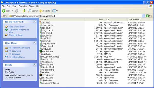
• MC is directory located at C:\Program Files\Measurement Computing\DAQ\
Revision: FEBRUARY 2021 19Note
The cb.cfg file is unique for the HCFM application. The .CFG file defines the A/D
channels and configures them for the pressure readings.
15. For 32-bit Windows XP/2000/Vista:
in order for HCFM to read pressure, check, and then copy if needed the CB.CFG file from:
C:\Program Files\Dynamax\HCFM\IcalUL\ CB.CFG
has been copied to:
C:\Program Files\Measurement Computing\DAQ\.
For 64-bit Windows XP/2000/Vista:
copy the CB.CFG file to
C:\Program Files(X86)\Measurement Computing\DAQ\.
For Windows 7, 8, 10 :
copy CB.CFG to
C:\ProgramData\Measurement Computing\DAQ\.
Revision: FEBRUARY 2021 2016. After installing the CFG files, we will add two drivers
for USB communication. Plug the HCFM USB cable
into one of the USB port on your PC, and connect
to the Measurement Computing USB2404-UI
device under the top of HCFM.
When prompted for New Hardware Found, select Yes,
this time only and click Next. Please select Install the
software automatically.
Another screen will pop up to notify you that a new device
has been detected, click OK to add. The USB carrier is
the generic loader for the USB2404 device.
Click Finish when done.
Revision: FEBRUARY 2021 21When a fully installed the USB Carrier drivers wizard will say:
17. Unplug and reconnect the USB cable between the HCFM
and the computer USB port. Allow one minute for Windows
to detect the USB2404-UI hardware, and install the software
protocol drivers.
When prompt New Hardware Found, select Yes, this time
only and click Next. Please select Install the software automatically.
USB2404-UI is the protocol for our HCFM-Gen3 to communicate
directly with the USB driven MC module (as opposed to a USB
driver that uses a COMx port.)
The next time you plug in the USB cable to the A/D converter,
there will be a message that the USB device is installed.
Now, the green LED on the USB2404-UI unit should start blinking.
To review a proper installation, of if there is any
doubt, one may check the device manager to
see the USB2404-UI device listed under the
DAS Component list:
Revision: FEBRUARY 2021 2218. After installing the device drivers, open
the InstaCal program from the desktop or the
START menu. Before actively using the icons
the serial number must be highlighted.
Then, click on Configure icon to confirm the settings.
Revision: FEBRUARY 2021 2319. Select tab USB-2404-UI, check the settings, and if required make the following changes:
• ADC Timing Mode: 50Hz for Europe and China
• ADC Timing Mode: Best 60Hz Rejects in U.S.A.
• Temperature units: Celsius
(DO NOT use fast mode)
Once these changes have been made click OK and proceed to the next step.
20. While under CH0 settings make the following changes:
• Channel Mode: Bridge
• Bridge Type: Full Bridge
• Range:+/-62mv/v
Once these changes have been made click OK and proceed to the next step
Revision: FEBRUARY 2021 2421. While under CH1 settings make the following changes:
• Channel Mode: Bridge
• Bridge Type: Full Bridge
• Range:+/-62mv/v
Once these changes have been made click OK and proceed to the next step
22. While under CH2 settings make the following changes:
• Channel Mode: Thermocouple
• TC Type: Type 2
Once these changes have been made click OK and proceed to the next step
Revision: FEBRUARY 2021 2523. At this time, or if any future need arises for a quick hardware test, you may run the InstaCal test.
Check on the “Test” tab and select the ANALOG option. A diagnostic screen will appear.
The voltages at zero pressure should be as shown, less than .004 V (27. Compare the contents of the two files. If they don’t match, copy it from CD and paste into the installed directory
mentioned above and overwrite the existing HCFM.ini document.
DO NOT make changes to this ini.file. The settings menu, and the data viewer allows for editing the values if necessary.
Normally this is not required except by a certified Dynamax technician.
Revision: FEBRUARY 2021 275. Setup for the HCFM
5.1 Operational Imperative
From the start, it is imperative that users of the HCFM take the following steps:
1. Always test for air bubbles in the HCFM prior to starting experiments. See Subsection 5.5, “Eliminating Air
from the HCFM” on use of software for methods of testing for air bubbles. Please see Subsection 8.0, “Tips
and Cautions” as well.
2. Connections between the Purple outlet of the 8WO and the compression fitting on the object must be checked.
In order to reduce elastic flow, always use small-diameter, rigid outlet tubing when using the two lowest flow
rate ranges (Green, Red and Orange). For high flow ranges ( Yellow, Gray and Brown) you may use the clear
1.5 mm ID Teflon FEP “Clear” tubing supplied by Dynamax. For low flow ranges (Green, Red and Orange)
ONLY use the 1.0 mm ID “Natural” (light tan) HPLC tubing supplied by Dynamax for connections between the
purple outlet of the 8WO and the compression fitting on the object to be measured.
NOTE:
DO NOT USE 0.12 mm ID RED TUBING FOR CONNECTION BETWEEN THE HCFM
AND A PLANT SAMPLE! The red tube is used only for testing and bubble removal
3. Carefully follow the instructions in Section 5.4.
5.2 Valve Setting for Preparing the HCFM for Service
The valve settings are important in removing air bubbles (gas) and keeping the air from infiltrating the system at
different points in the handling, use, and storage of the HCFM. During the storage of the HCFM unit make sure
that the purple outlet value is closed.
5.3 Pressurizing the HCFM
The HCFM uses a pressure bottle filled with nitrogen or air (your choice) to force water into the root, stem, or shoot. This
pressure bottle can be filled to a pressure of 15 MPa (2,200 PSI). The bottle is shipped empty for safety reasons. To fill the
bottle, contact your local gas distributor or physical plant. Depending on your preference or economics, the bottle can be
filled with either air or nitrogen.
Gauges Specification on the regulator:
Supplying Pressure Display – 4000 PSI (Max)
Delivery Pressure Display – 1000 PSI (Max)
The bottle also has a pressure regulator that is attached to the top of the bottle using a screw clamp. Follow the directions
enclosed for attaching the regulator to the bottle correctly. Use soapy water or a commercial product such as “Snoop” to
check for leaks not only in the regulator-to-bottle connection, but the other hose connections as well.
Revision: FEBRUARY 2021 28WARNING!
Do not pressure the compressed air supply hose to above 690 kPa (100 PSI)
while the hose is disconnected! Do not disconnect or connect the hose if
the pressure is above 40 kPa (20 PSI)!
5.3.1 Tips for Setting the Pressure Regulator
The valve at the top of the bottle should not be opened until the regulator pressure set screw is backed off
completely. Once this is done, open the valve on the bottle completely. Check the bottle pressure gage. The pressure should
be at least 4.15 Mpa (600 PSI). This pressure is required when running a transient state flow. The minimum pressure forces
enough compressed gas to the captive air tank (CAT) to keep a steady, linear pressure increase during the test. Close the
tank valve, and release the hose pressure by pressing on the valve release needle.
WARNING!
Do not pressure the compressed air supply hose to above 689 kPa
(100 PSI) while the hose is disconnected! Do not disconnect or connect the
hose if the pressure is above 70 kPa (10 PSI)!
Photo 1
Air Regulator Pressure
The “disconnects” on the air pressure hose and HCFM system has a working pressure of 690 kPa (100 PSI). Pressure on
the disconnect seals above 690 kPa (100 PSI) could cause a catastrophic failure of the “disconnect system” or personal
injury. You also can generate a loud, annoying “pop” sound unless the pressure is released first.
Increase the air regulator pressure to 138 kPa (20 PSI) and check for leaks again. Decrease the pressure by backing off the
regulator screw. Depress the end of the “disconnect” into a hard flat surface such as a coin. This will open the discon-
nect seal and release the small amount of gas in the hose.
Revision: FEBRUARY 2021 295.3.2 Preparing the Compressed Air Supply System for use with the HCFM
Connect the hose quick-disconnect (Male) into the HCFM compressed air supply quick-disconnect (Female).
Make sure that the needle valve is opened about 4 turns. The airflow control valve (AV) should be closed, pointed towards
the right. Remember that turning the valve towards Bleed Out will release pressure from the HCFM. Turning the valve
down will increase pressure when the compressed air supply is connected. If you are setting up to measure a quasi-steady
state flow, turn the Needle Valve (NV) next to AV until the digital gage reads ~550 kPa (~80 PSI). Do not go over 550 kPa
(~80 PSI). The HCFM has a safety relief valve which is set for ~650 kPa (~95 PSI).
If you wish to test the unit or run a quasi-steady state flow test, open the Compressed Air Valve until there is a
steady increases in the pressure in the CAT. Fill the CAT at a rate of about 7-10 kPa (1-1.5 PSI) per second. The
Needle Valve can be used to regulate the rate of increasing pressure. Close the Compressed Air Valve (AV in
Photo 4 page 34) when you have reached the required pressure in a range from 200 to 500 kPa (29 to 72 PSI).
Photo 2
Compressed Air & HCFM near Connection
WARNING!
Do not attempt to adjust or “plug” the safety relief valve!
If you are doing a transient pressure test, release CAT pressure at 0 to 7 kPa (0 to 1 PSI) and turn the pressure regulator
screw until the outlet pressure is at least 4.1 Mpa (600 PSI). Make sure that the needle valve is opened about 2-3 turns so
that the pressure increases about 7kPa(1 PSI) per second. Open Compressed Air Valve only in conjunction to starting the
software for the test. The “disconnect” on the air pressure hose and HCFM system has a working pressure of 690 kPa (100
PSI.) Pressure on the disconnect seals above 690 (100 PSI) could cause a catastrophic failure of the “disconnect system”
or personal injury. You also can generate a loud, annoying “pop” sound unless the pressure is released first.
Increase the air regulator pressure to 140 kPa (20 PSI) and check for leaks again. Decrease the pressure by backing off the
regulator screw. Depress the end of the “disconnect” into a hard flat surface such as a coin. This will open the disconnect
seal and release the small amount of gas in the hose.
Revision: FEBRUARY 2021 305.4 Adding De-gassed Water to the HCFM
The Captive Air Tank (CAT) is a two-compartment tank. The left compartment contains water and the right compartment
can be pressurized with air. A flexible rubber diaphragm separates the two compartments. The CAT allows you to pressurize
the water without the air and water mixing together. The CAT will hold 21 oz. of water and it is best to refill while there is still
at least 5 oz of water in the tank. If the CAT is initially empty then refer to Subsection 5.4.2, “Priming a totally empty
tank.”
CAUTION!
Always use Distilled Degassed Water in the HCFM.
If the dissolved air effervesces, or the air comes out of solution (much in the same way a soda pop will effervesce when
the can is opened), then air bubbles will form. These air bubbles will compress as the pressure increases. However, when the
water is flowing from the HCFM and the pressure decreases, the air can come out of the solution. Air and water behave
differently when compressed, or pressurized. Water, for the most part does not compress, with its volume changing little. Air
will compress with great changes in the volume that the air occupies. That large change is why air must be removed from
the HCFM system.
The water added must have the air removed. There are two accepted ways for removing the absorbed air from water. The
easiest way is to “boil” the water or raise the temperature of the water to the vapor point of water 100° C (212 °F.)However
boiling removes less than half the air. A more effective way is place the water in a vacuum.
Degassing the distilled water is explained in Subsection 5.4.1, “Making Degassed Water /
Preventing Algae Buildup Inside the HCFM.”
Your HCFM system comes with a HCFM refill kit. The refill kit is a 32 oz bottle (shown to the right).
The Refill Kit conveniently allows refilling of the HCFM just about anywhere.
There are a few important things to remember about the HCFM. The first is to always visually
check the level of the degassed water in the HCFM Refill Kit. The degassed water level should
never go below the siphon point inside the Refill Kit tank. If air were introduced into the HCFM
system during filling, then this would mean removing the air ‘and follow the procedures in Section
5.5, “Eliminating Air from the HCFM.”
Photo 3
Refill Kit
CAUTION!
If degassed water is kept in the refill container more than a few minutes under
pressure it will become supersaturated with air again. So fill immediately after
degassing!
Revision: FEBRUARY 2021 315.4.1 Making Degassed Water / Preventing Algae Buildup Inside the HCFM
The Captive Air Tank (CAT) should be filled only with ‘degassed water’, i.e., water with air dissolved at less than saturating
concentrations of O2 and N2 at atmospheric pressure. There are two methods of making degassed water. The first
method is to boil water. This removes some of the absorbed gas because air is less soluble in hot water than cold water.
If this method is used, the CAT could be filled while the water is still hot.
The steps for boiling the distilled water for the HCFM are:
WARNING
Take Precautions. Use Gloves when handling the Hot Degassed Water.
1. Start off with a 3.8 L (~1 gallon) of distilled water. Distilled Water is convenient and easy to obtain. It is even
available in most food markets.
2. Boil the distilled water for 5 minutes.
3. Let the distilled boiled water stand for 10-15 minutes before handling and adding the water to the refill kit.
4. Add one drop of algaecide (from the HCFM accessories kit) to the distilled water.
5. If the HCFM is new, it will be shipped empty. Repeat steps 1 through 4 so that you will have 24 oz. of water to
fill the CAT.
6. If the HCFM is brand new or has never been used, proceed to Subsection 5.4.2, “Priming a totally
empty CAT.”
The other method is to put water into a vacuum flask and draw a vacuum over the water for 5 to 10 minutes. The steps for
this procedure are:
1. Place the distilled water in a vacuum flask. Fill the flask to its logical level. Do not over fill. Distilled Water
is convenient and easy to obtain. It is even available in most food markets.
2. Vacuum the distilled water for 5 minutes from the time that the water begins to effervesce with air bubbles or
“boil” at room temperature. If the vacuum is really good you should see the water boil at room temperature
when the pressure drops below about 4 kPa (0.6 PSI) absolute. Slowly release the vacuum to an atmospheric
pressure.
3. Pour the newly degassed water into a secondary container. Repeat steps 1 and 2 until one gallon of degassed
water has been produced.
4. Add one drop of algaecide (from the HCFM accessories kit) to the distilled water.
5. If the HCFM is new, it will be shipped empty. Repeat steps 1 through 4 so that you will have 24 oz. of water to
fill the CAT.
6. If the HCFM is new or been shipped, proceed to Subsection 5.4.2, “Priming a Totally Empty CAT.” The tank
should be filled immediately after degassing the water by vacuum. Use the Refill Kit to insert the degassed
water into the Captive Air Tank of the HCFM as quickly as possible.
Revision: FEBRUARY 2021 325.4.2 Priming a Totally Empty Captive Air Tank (CAT)
When first priming the HCFM or if air bubbles have entered into the HCFM system, you must pre fill the CAT with at least
21 oz. of degassed distilled water before you can start the priming process. If the HCFM has had water already
added, please skip this subsection and move on to Subsection 5.4.3, “Adding water to a Partially Empty Captive Air Tank
(CAT).” This pre-fill will assist in the removal of all air bubbles. Removing air bubbles as in Section 5.5, “Eliminating Air from the
HCFM” is a requirement for normal operation of the HCFM. Another requirement is the removal of small microscopic bubbles
that form inside the wetted areas of the HCFM and adhere to the surfaces. Note that parts of the series of instructions are very
much like Subsection 5.4.3. That is because you must fill the HCFM unit with water to remove the air bubbles first. The
steps for priming the empty HCFM CAT are:
1. Make sure that all valves are closed
2. If there is pressure, begin to release the pressure with the Compressed Air Supply Valve. To release pressure,
slowly turn the valve to the bleed air position (right)
3. Once the pressure is removed, close the Compressed Air Supply Valve
WARNING!
Cover the “disconnect” and screwdriver with a towel to keep the hot water from
spraying.
4. Raise the refill tubing straight upward. Depress the Refill Kit male “disconnect” against a hard object, such as a
flat blade screwdriver, allowing the water to flow and remove bubbles from the Refill Kit tubing.
WARNING!
Take Precautions. Use Gloves when handling the HOT Degassed Water.
5. Connect the Refill Kit to the HCFM. Once the connector is snapped shut, turn the water valve to the left and
proceed to using the following steps:
a. Make sure that there is degassed water in the Refill Kit. If not, go to Subsection 5.4.1,
“Making Degassed Water.” Fill the refill bottle with approximately 28 oz of degassed water. Some of the
excess water will be used for the removal of extraneous bubbles from the tubing, root compression
fittings, etc.
b. Open the Water Supply Valve (pointing down) to allow the water to flow into the CAT. Connect the Refill
Kit to the HCFM and check the tubing for air bubbles and leaks.
c. Squeeze the refill bottle using the air inside to push the water into the system. When you can no longer
squeeze release the refill bottle re-inflating it with air, so you can squeeze more water inside. Note the
digital pressure gage will show increasing pressure inside of the CAT.
d. When the tank pressure gage reaches 15 kPa (2-3 PSI), turn the Compressed Air Supply valve
to bleed the pressure from the HCFM System.
e. Make sure that you do not allow air from the Refill Kit to enter into the HCFM. Stop when you have
about 8 oz of water left in the refill kit.
f. Once the HCFM is filled, close the Water Supply Valve.
Revision: FEBRUARY 2021 33You can also read