Idaho Design and Installation Manual - September 2018 - Eljen Corporation
←
→
Page content transcription
If your browser does not render page correctly, please read the page content below
Geotextile Sand Filter

 Idaho
 Design and Installation Manual

 September 2018

125 McKee Street
East Hartford, CT 06108
Tel: 800-444-1359
Fax: 860-610-0427
www.eljen.com

2021 Idaho Design & Installation Manual Page 1 www.eljen.com

Table of Contents

SUBJECT PAGE

 GLOSSARY OF TERMS .................................................................................................................. 3
 GSF SYSTEM DESCRIPTION ........................................................................................................ 4
 1.0 SYSTEM PRECONDITIONS ..................................................................................................... 5
 2.0 DESIGN AND INSTALLATION .................................................................................................. 6
 3.0 TRENCH INSTALLATION SIZING AND GUIDELINES ........................................................... 10
 4.0 BED INSTALLATION SIZING AND GUIDELINES .................................................................. 13
 5.0 CAPPING FILL SYSTEM GUIDELINES .................................................................................. 16
 6.0 MOUND INSTALLATION SIZING AND GUIDELINES ............................................................ 17
 7.0 DOSING DISTRIBUTION GUIDANCE .................................................................................... 22
 8.0 PRESSURE DISTRIBUTION GUIDANCE ............................................................................... 22
 9.0 SYSTEM VENTILATION .......................................................................................................... 24
 10.0 GSF INSPECTION CHECK LIST .......................................................................................... 26

GSF DRAWINGS AND TABLES

 DRAWINGS
 FIGURE 1: GSF SYSTEM OPERATION ........................................................................................ 4
 FIGURE 2: TYPICAL A42 CROSS SECTION ................................................................................ 6
 FIGURE 3: SEQUENTIAL DISTRIBUTION DROP–BOX DETAIL................................................... 8
 FIGURE 4: TRENCH CROSS SECTION ........................................................................................ 9
 FIGURE 5: PLAN VIEW –TRENCH SYSTEM ............................................................................... 11
 FIGURE 6: SECTION VIEW – TRENCH SYSTEM – LEVEL SITE ................................................ 11
 FIGURE 7: SECTION VIEW – TRENCH SYSTEM – SLOPING SITE ........................................... 11
 FIGURE 8: PLAN VIEW – BED SYSTEM ...................................................................................... 14
 FIGURE 9: SECTION VIEW – BED SYSTEM ............................................................................... 14
 FIGURE 10: TYPICAL A42 CROSS SECTION ............................................................................ 16
 FIGURE 11: TYPICAL A42 CROSS SECTION ............................................................................ 16
 FIGURE 12: CROSS SECTION – MOUND SYSTEM .................................................................... 17
 FIGURE 13: PLAN VIEW – MOUND SYSTEM............................................................................... 17
 FIGURE 14: PLAN VIEW – ELJEN BED CELL............................................................................... 20
 FIGURE 15: PRESSURE PIPE PLACEMENT .............................................................................. 22
 FIGURE 16: PRESSURE CLEAN OUT ......................................................................................... 23
 FIGURE 17: CONTOURED TRENCH PRESSURE DISTRIBUTION ............................................ 23
 FIGURE 18: VENT LAYOUTS FOR GRAVITY AND LOW-PRESSURE SYSTEMS ..................... 24
 FIGURE 19: AIR BY-PASS LINE PLAN VIEW FOR VENTING OF PUMPED SYSTEMS ............. 24
 FIGURE 20: GSF WITH 4” VENT EXTENDED TO CONVENIENT LOCATION ............................ 25

 TABLES
 TABLE 1: SPECIFIED SAND SIEVE REQUIREMENTS ................................................................ 3
 TABLE 2: VERTICAL SEPARATION .............................................................................................. 6
 TABLE 3: APPLICATION RATES ................................................................................................... 9
 TABLE 4: SQUARE FOOTAGE PER A42 PER TRENCH APPLICATION .................................... 9

2021 Idaho Design & Installation Manual Page 2 www.eljen.com
Glossary of Terms

 A42 Module 48” x 24” x 7” (L x W x H)
 Cover Fabric The geotextile cover fabric (provided by manufacturer) that is placed over the
 GSF modules.
 Design Flow The estimated peak flow that is used to size a GSF system for a 3-bedroom
 single family dwelling or mobile home is 250 gallons per day +/- 50
 gallons/Bedroom.
 Flow Dial/Equalizer Special insert placed in the end of distribution pipes within the distribution box
 to compensate for possible unlevel installation and promote favorable flow to the
 distribution pipes.
 GSF The Eljen Geotextile Sand Filter Modules and the 6-inch sand layer at the base
 and the 6-inch layer along the sides of the modules.
 GSF Module The individual module of a GSF system. The module is comprised of a cuspated
 plastic core and geotextile fabric.
 Specified Sand To ensure proper system operation, the system MUST be installed with Medium
 Sand as specified in the Idaho Technical Guidance Manual, 3.2.8.1.2 Medium
 Sand. Sand must be used with not more than 10% passing the #100 Sieve and
 not more than 2% passing the # 200 sieve. Ask your material supplier for a sieve
 analysis to verify that your material meets the required specifications.

 TABLE 1: SPECIFIED SAND SIEVE REQUIREMENTS

 3.2.8.1.2 MEDIUM SAND
 SAND SPECIFICATION

 Specification
 Sieve Square
 Sieve Size Percent Passing
 Opening Size
 (Wet Sieve)

 3/8 inch 9.52 mm 100
 No. 4 4.76 mm 95 - 100
 No. 8 2.38 mm 80 - 100
 No. 16 1.19 mm 50 - 85
 No. 30 590 µm 25 - 60
 No. 50 297 µm 10 - 30
 No. 100 149 µm 2 - 10
 No. 200 75 µm
GSF System Description

 Primary Treatment Zone
 • Perforated pipe is centered above the GSF module to distribute septic effluent over and into
 corrugations created by the cuspated core of the geotextile module.
 • Septic effluent is filtered through the Bio-Matt fabric. The module’s unique design provides increased
 surface area for biological treatment that greatly exceeds the module’s footprint.
 • Open air channels within the module support aerobic bacterial growth on the modules geotextile fabric
 interface, surpassing the surface area required for traditional absorption systems.
 • An anti-siltation geotextile fabric covers the top and sides of the GSF module and protects the
 Specified Sand and soil from clogging, while maintaining effluent storage within the module.

 Secondary Treatment Zone
 ▪ Effluent drips into the Specified Sand layer and supports unsaturated flow into the native soil. This
 Specified Sand/soil interface maintains soil structure, thereby maximizing the available absorption
 interface in the native soil. The Specified Sand supports nitrification of the effluent, which reduces
 oxygen demand in the soil, thus minimizing soil clogging from anaerobic bacteria.
 • The Specified Sand layer also protects the soil from compaction and helps maintain cracks and
 crevices in the soil. This preserves the soil’s natural infiltration capacity, which is especially
 important in finer textured soils, where these large channels are critical for long-term
 performance.
 • Native soil provides final filtration and allows for groundwater recharge.

 FIGURE 1: GSF SYSTEM OPERATION

2021 Idaho Design & Installation Manual Page 4 www.eljen.com
1.0 System Preconditions

1.1 REQUIREMENTS: GSF systems must meet the local rules and regulations except as outlined in this
manual. The Idaho Regulations IDAPA.58.01.03.009.02 and the local regulations will be referred to as the
guidelines.
Contact our technical department if a question arises to components and configurations not covered in this
manual. Local approving authorities can request written consent regarding components and configurations
from Eljen to ensure compliance.
The sizing charts apply to residential systems only and are found in section 2.16. Please contact Eljen’s
Technical Resource Department at 1-800-444-1359 for design information on commercial systems.
1.2 GARBAGE DISPOSALS: The use of a garbage disposal is not recommended as they can cause septic
system problems by generating an increase of suspended solids, grease and nutrients.
However, if such units are proposed to be used, other measures should be taken to mitigate the increased
nutrients to the field. Consult your local and state code for garbage disposal requirements. Eljen
recommends a dual compartment tank or tanks in series. Consider upsizing the field for the additional
biological load.
NOTE: Eljen requires the use of septic tank outlet effluent filters on all systems. Filters with higher filtration
are recommended for systems with garbage disposals.
1.3 ADDITIONAL FACTORS AFFECTING RESIDENTIAL SYSTEM SIZE: Homes with expected higher
than normal water usage may consider increasing the septic tank volume as well as incorporating a multiple
compartment septic tank. Consideration for disposal area may be up-sized for expected higher than normal
water use.
For example:
 • Luxury homes, homes with a Jacuzzi style tubs, and other high use fixtures.
 • Homes with known higher than normal occupancy.
1.4 SYSTEM PROHIBITED AREAS: All vehicular traffic is prohibited over the GSF system. GSF systems
shall not be installed under paved or concreted areas. If the system is to be installed in livestock areas, the
system must be fenced off around the perimeter to prevent compaction of the cover material and damage
to the system.
1.5 ELJEN INSTALLER CERTIFICATION: All installers are required to be trained and certified by an
authorized Eljen representative. Contact your local distributor for training information.

2021 Idaho Design & Installation Manual Page 5 www.eljen.com
2.0 Design and Installation

 FIGURE 2: TYPICAL A42 CROSS SECTION

 SEED AND LOAM

 MIN 12" OF GEOTEXTILE
 CLEAN FILL FABRIC

 7"

 SPECIFIED SAND
 12"

 6" 24" 6"
 36"

 A42 MODULE (L X W X H) 48” X 24” X 7”

 All systems are required to have a minimum of:

 • 6 inches of Specified Sand is at the edges of the GSF module.
 • 6 inches of Specified Sand is at the beginning and end of each GSF Row.
 • 12 inches of Specified Sand is directly below the GSF module.
 • Minimum 12 inches of cover above the module.

2.0 Design and Installation

2.1 SEPTIC TANK: Septic tanks should be fitted with an effluent filter and sized according to state
regulations. Many designers are now specifying dual compartment tanks for all their systems. Eljen
supports this practice as it helps to promote long system life by reducing TSS and BOD to the effluent
disposal area. Gas baffles and/or effluent filters are also recommended. Tanks shall meet the requirements
of TGM Section 5.2
2.2 SEPTIC TANK FILTERS: Septic tank effluent filters are REQUIRED on the outlet end of septic tank.
Filter manufactures require that filters be cleaned from time to time. Ask your installer or designer for specific
cleaning requirements based on the type or make of the filter installed. Eljen requires the septic tank to be
pumped every three years or as needed which would be a good time to check and conduct filter
maintenance. Refer to section 5.9 of the Idaho Technical Guidance Manual for approved Septic Tank
Effluent Filters.
2.3 VERTICAL SEPARATION TO LIMITING LAYER:
 TABLE 2: VERTICAL SEPARATION
 Idaho TGM Table 4.19 Recirculating gravel filter vertical Flow < 2,500 Flow ≥ 2,500
 separation to limiting layers (feet). Limiting Layer GPD GPD
 All Soil All Soil
 Types Types
 Impermeable layer 2 4
 Fractured rock or very porous layer 1 2
 Normal high ground water 1 2
 Seasonal high ground water 1 2

2021 Idaho Design & Installation Manual Page 6 www.eljen.com
2.0 Design and Installation

2.4 SPECIFIED SAND SPECIFICATION FOR GSF SYSTEMS: The sand immediately under, between
rows and around the perimeter of the GSF system must meet 3.2.8.1.2 Medium Sand of the Idaho Technical
Guidance Manual, WITH 2-10% PASSING A #100 SIEVE AND LESS THAN 2% PASSING A #200 SIEVE.
Please place a prominent note to this effect on each design drawing. See Table 1 for more information on
the sand and sieve specifications.
2.5 PLACING GSF MODULES: The “painted stripe” on the GSF modules indicates the top of the module
and is not intended to indicate the location of the distribution pipe. With the painted stripe facing up, all
rows of GSF modules are set level, end to end on the Specified Sand layer.
2.6 DISTRIBUTION: Gravity, pump to gravity or pressure distribution are acceptable when using the GSF
System. Piping shall meet the requirements guidelines; however, Eljen strongly recommends the use of
SDR 35 pipe and fittings as to prevent crushing during backfill. All distribution piping must meet a minimum
2,500-pound crush test specification for polyvinyl chloride (PVC) drain, waste and vent pipe.
All systems require a perforated 4” diameter pipe centered on top of the GSF modules unless the system
is curving. The distribution pipe continues along the entire length of all modules in a trench or row. Holes
are set at the 4 and 8 o’clock position and secured by the Eljen provided wire clamps.
When using pressure distribution, a pressure manifold is placed inside the 4-inch distribution pipe. Section
8.0 of this manual goes into details of how to construct the distribution network. All piping must meet state
and local regulations.
2.7 CONNECTIONS AND FITTINGS: Connections of lines to tanks and distribution boxes must be made
using watertight seals. Use of any grouting material is not permitted.

2.8 DISTRIBUTION BOX: Set the gravity system D-box outlet invert a minimum of ⅛ inch drop in elevation
per linear foot to the top first module in the row. Set a 2-inch minimum drop for dosed systems from the D-
box to the modules. Ensure that the distribution box and pipes feeding the system are placed on compacted
soil. Flow Dials may be used in either Gravity or Dosed installations.

2.9 INSTALLING ON SLOPING TERRAIN: For trench systems, edge-to-edge trench spacing will be a
minimum of 6 feet. For bed systems, edge-to-edge minimum spacing will be 1 feet (lateral to lateral of 3 feet).
Provide a D-box at the beginning of the first row of modules for effluent distribution and velocity reduction and
as a system inspection port. Lower rows may also be loaded from one or more D-boxes with Flow Dials to
insure effluent is distributed per design requirements. Serial or equal distribution is permitted.
Equal Distribution: Set Flow Dials to insure effluent is distributed equally to all rows in the system.
Serial Distribution: Set Flow Dials to insure effluent is loaded to the upslope trench first before continuing to
lower trenches within the system.

2.10 EQUAL DISTRIBUTION: Parallel distribution is the preferred method of dosing to a gravity or pump
to gravity system. It encourages equal flows to each of the lines in the system. It is recommended for most
trench systems.

2.11 SEQUENTIAL DISTRIBUTION: Sequential Distribution using a distribution box will fully utilize the
uppermost section of the system prior to spilling effluent into a lower row of modules. This is for use on
any site with greater than 0.5% slope when not using parallel distribution.

2021 Idaho Design & Installation Manual Page 7 www.eljen.com
2.0 Design and Installation

 FIGURE 3: SEQUENTIAL DISTRIBUTION DROP–BOX DETAIL
 B A

 GSF MODULES
 DIAL-A-FLOW UPPER MOST TRENCH
 INVERT SETTING
 DIAL-A-FLOW FITTINGS ARE NOT
 INSTALLED ON THE OVER FLOW LINE
 FROM THE SEPTIC TANK
 B A OR THE DISTRIBUTION PIPE
 LEADING TO THE GSF MODULES
 GSF MODULES
 LOWER TRENCHES

 THE INVER OF DIAL-A-FLOW "B"
 IS SET AT THE 9:00 POSITION
 GSF MODULES
 LOWEST TRENCH
 DIAL-A-FLOW FITTINGS ARE NOT INSTALLED
 ON THE OVER FLOW LINE FROM A UPPER DROP-BOX
 OR THE DISTRIBUTION PIPE
 LEADING TO THE GSF MODULES

 THE INVER OF DIAL-A-FLOW "B"
 THE LOWEST TRENCH ALONG THE SLOPE IS SET AT THE 9:00 POSITION
 DOES NOT REQUIRE A DROP-BOX, ALTHOUGH
 RECOMMENDED WITH COMMERCIAL DESIGNS OUTFLOW TO
 FOR INSPECTION AND OBSERVATION DOWNSIDE
 DROP BOX
 IN FLOW FROM SEPTIC TANK,
 PUMP CHAMBER OR UP SLOPE
 DROP BOX
 OUTFLOW TO
 DOWNSIDE SLOPE
 DROP BOX
 OUTFLOW TO GSF
 LATERAL LINE
 IN FLOW FROM SEPTIC TANK, OUTFLOW TO
 PUMP CHAMBE OR UP SLOPE DOWNSIDE SLOPE
 DROP BOX DROP BOX

 OUTFLOW TO GSF
 LATERAL LINE

2.12 COVER FABRIC: Geotextile cover fabric is provided by Eljen Corporation for all GSF systems. It is
placed over the top and sides of the module rows to prevent long term siltation and failure. Cover fabric
substitution is not allowed. Fabric should drape vertically over the pipe and must not block holes in the
distribution pipe or be stretched from the top of the pipe to the outside edge of the modules. “Tenting” will
cause undue stress on fabric and pipe.

2.13 SYSTEM VENTING: It is required to vent all systems that are over 18” below finished grade and
systems beneath any surface condition that would not allow for surface air exchange with the system such
as patios. See Section 9.0 for a more detailed explanation of venting GSF products.

2.14 BACKFILL & FINISH GRADING: Complete backfill with a minimum of 12 inches of clean porous fill
measured from the top of modules. Use well graded sandy fill that is clean, porous and devoid of large
rocks. Do not use wheeled equipment over the system. A light track machine may be used with caution,
avoiding crushing or shifting of pipe assembly. Divert surface runoff from the system absorption area.
Finish grade to prevent surface ponding. Seed and loam system area to protect from erosion.

2.15 SYSTEM GEOMETRY: Design systems as long and narrow as practical along site contours to
minimize ground water mounding especially in poorly drained low permeability soils. If possible, design
level systems with equal number of modules per row.
There is a minimum 6-foot separation between trenches, measured from sidewall to sidewall.
In bed systems, it is acceptable to space the units to maximize points of application to the basal area.
Laterals shall be no greater than 6 feet on centers and no greater than 4 feet from the sidewalls.
2.16 NUMBER OF GSF MODULES REQUIRED: Residential systems use a minimum of six (6) modules
per bedroom. See Section 2.17 for more information on systems sizing.

2021 Idaho Design & Installation Manual Page 8 www.eljen.com
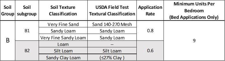
2.0 Design and Installation

2.17 SYSTEM SIZING: When determining the correct sizing for your GSF system, it is important to follow
your local codes and regulations for proper surface and subsurface classifications.

 TABLE 3: APPLICATION RATES

 Minimum Units Per
 Soil Soil Soil Texture USDA Field Test Application
 Bedroom
Group subgroup Classification Textural Classification Rate
 (Bed Applications Only)
 A1 Medium Sand 30-60 Mesh 1.7
 A2a Medium Sand Poorly Graded 1.2
 A Fine Sand Sand 60-140 Mesh
 6
 A2b 1.0
 Loamy Sand Sand
 Very Fine Sand Sand 140-270 Mesh
 B1 Sandy Loam Sandy Loam 0.8
 Very Fine Sandy Loam Sandy Loam
 B Loam ─
 9

 B2 Silt Loam Silt Loam 0.6
 Sandy Clay Loam (≤27% Clay )
 Silt Silt Loam
 C1 Sandy Clay Loam Clay Loam (≥27% Clay) 0.4
 C Silty Clay Loam Clay Loam
 12

 C2 Clay Loam Clay Loam 0.3
 1. Per IDAPA 58.01.03.008.04, the bottom of the System Sand excavation must be installed level.
 2. Systems with percolation rates in excess of 120 MPI are not allowed.
 3. Drainfields larger than 1,500 ft2 trench area bottom are prohibited from being constructed as standard (gravity)
 4. Per IDAPA 58.01.03.008.04, a “Trench” is up to 6’ wide, anything wider is considered a bed.
 5. Maximum site slope per IDAPA 58.01.03 rules.

2.18 TRENCH SQUARE FOOTAGE BY TRENCH WIDTH:
 TABLE 4: SQUARE FOOTAGE PER A42 PER TRENCH APPLICATION

 TRENCH WIDTH SAND EXTENSION SQUARE FOOT PER MODULE
 3 FOOT 6 INCHES 12
 4 FOOT 12 INCHES 16
 5 FOOT 18 INCHES 20
 6 FOOT 24 INCHES 24

 FIGURE 4: TRENCH CROSS SECTION

 SPECIFIED SAND

 SAND 24" SAND
 EXTENSION EXTENSION

2021 Idaho Design & Installation Manual Page 9 www.eljen.com
3.0 Trench Installation Sizing and Guidelines

Trench Example:
House size: 3 Bedrooms
Design Flow: 250 gpd
Soil Type: Soil B2; Silt Loam (0.6 gpd/sf)
Absorption Field Type: Trench

Calculate Minimum Absorption Area
Lookup loading rate from Table 3 and determine the loading rate:

 Minimum Units Per
 Soil Soil Soil Texture USDA Field Test Application
 Bedroom
Group subgroup Classification Textural Classification Rate
 (Bed Applications Only)
 Very Fine Sand Sand 140-270 Mesh
 B1 Sandy Loam Sandy Loam 0.8
 Very Fine Sandy Loam Sandy Loam
 B Loam ─
 9

 B2 Silt Loam Silt Loam 0.6
 Sandy Clay Loam (≤27% Clay )
 Absorption Area: Design Flow ÷ Loading Rate
250 gpd ÷ 0.6 gpd / ft2 = 416.66 ft2
Calculate Number of Modules Required
 TRENCH WIDTH SAND EXTENSION SQUARE FOOT PER MODULE
 3 FOOT 6 INCHES 12
 4 FOOT 12 INCHES 16
 5 FOOT 18 INCHES 20
 6 FOOT 24 INCHES 24

 Number of units required = Absorption Area ÷ Square Foot Per Module
Units required
417 ft2 ÷ 12 ft2 / module = 34.7 Modules
Round to: 35 Modules

Calculate Minimum Trench Length
35 Units x 4 + 1 141 linear feet
Trench Width
Trench width = unit width + sand extension
36 = 24” + 12” (6” sand both sides of unit) 3 ft.
Final Dimension Layout
(Note: System layout and number of rows will vary based on site constraints)

Min. Product Length 140 ft.
(note: 6 inches of sand required at each end of trench which makes the minimum trench length 141 ft.
Trench Width 3 ft.
Minimum Number of Units 35 Modules
2 Trench Rows 18 Modules each row, 73 ft. per row.
Min. System Area 420 ft2

2021 Idaho Design & Installation Manual Page 10 www.eljen.com
3.0 Trench Installation Sizing and Guidelines

 FIGURE 5: PLAN VIEW –TRENCH SYSTEM
 6" SPECIFIED SAND 6"

 2'

 MIN 6' NATIVE SOIL

 3'

 40'
 41'

 FIGURE 6: SECTION VIEW – TRENCH SYSTEM – LEVEL SITE
 SEED AND LOAM

 GEOTEXTILE
 FABRIC
 7"
 NATIVE SOIL
 12"
 SPECIFIED SAND SPECIFIED SAND
 24"
 36" MIN 6' 36"

 FIGURE 7: SECTION VIEW – TRENCH SYSTEM – SLOPING SITE
 SEED AND LOAM

 GEOTEXTILE
 FABRIC
 7"
 NATIVE SOIL
 12" SPECIFIED SAND
 SPECIFIED SAND

 24"
 36" MIN 6' 36"

2021 Idaho Design & Installation Manual Page 11 www.eljen.com
3.0 Trench Installation Sizing and Guidelines

1. Ensure all components leading to the GSF system are installed properly. Septic tank effluent filters are
 required with the GSF system.

2. Determine the number of GSF Modules required using the trench sizing example.

3. Prepare the site. Do not install a system on saturated ground or wet soils that are smeared during
 excavation. Keep machinery off infiltrative areas.

4. Plan all drainage requirements above (up-slope) of the system. Set soil grades to ensure that storm
 water drainage and ground water is diverted away from the absorption area once the system is
 complete.

5. Excavate the trench; scarify and prepare the receiving layer to maximize the interface between the
 native soil and specified sand.

6. Minimize walking in the trench prior to placement of the specified sand to avoid soil compaction.

7. Place specified sand in a 6” lift and stabilize by foot, a hand held tamping tool or a portable vibrating
 compactor. The minimum stabilized height below the GSF module must be level at 12”.

8. Place GSF modules with PAINTED STRIPE FACING UP, end to end on top of the specified sand along
 their 4-foot length.

9. A standard 4-inch perforated pipe, SDR 35 or equivalent, is centered along the modules 4-foot length.
 Orifices are set at the 4 & 8 o’clock position.

10. All 4-inch pipes are secured with manufacturers supplied wire clamps, one per module.

11. (Pressure Distribution Systems) Insert a pressure pipe (size per design and code) into the standard 4-
 inch perforated pipe. The pressure pipe orifices are set at the 12 o’clock position as shown in Figure
 15. Each pressure lateral will have a drain hole at the 6 o’clock position. Each pressure lateral shall
 include sweeping cleanouts at the terminal ends and be accessible from grade. The distribution pipe
 is capped at both ends with a hole cut throw to allow the pressure pipe through.

12. Cover fabric substitution is not allowed. The installer should lay the Eljen provided geotextile cover
 fabric lengthwise down the trench, with the fabric fitted to the perforated pipe on top of the GSF
 modules. Fabric should be neither too loose, nor too tight. The correct tension of the cover fabric is
 set by:
 a. Spreading the cover fabric over the top of the module and down both sides of the module
 with the cover fabric tented over the top of the perforated distribution pipe.
 b. Place shovelfuls of Specified Sand directly over the pipe area allowing the cover fabric to
 form a mostly vertical orientation along the sides of the pipe. Repeat this step moving down
 the pipe.

13. Place the sand extensions along both sides of the modules edge. A minimum of 6 inches of Specified
 Sand is placed at the beginning and end of each trench.

14. Complete backfill with a minimum of 12 inches of clean porous fill measured from the top of the module.
 Backfill exceeding 18 inches requires venting at the far end of the trench. Use well graded native soil
 fill that is clean, porous and devoid of large rocks. Do not use wheeled equipment over the system. A
 light track machine may be used with caution, avoiding crushing or shifting of pipe assembly.

15. Divert surface runoff from the system. Finish grade to prevent surface ponding. Topsoil and seed
 system area to protect from erosion.

2021 Idaho Design & Installation Manual Page 12 www.eljen.com
4.0 Bed Installation Sizing and Guidelines

Bed Example:
House size: 3 Bedrooms
Design Flow: 250 gpd
Soil Type: Silt Loam (0.6 gpd/sf)
Absorption Field Type: Bed
Calculate Minimum Absorption Area
Lookup loading rate from Table 3:

 Absorption Area: Design Flow ÷ Loading Rate
250 gpd ÷ 0.6 gpd = 416 ft2
Calculate Number of Modules Required
Lookup units required per bedroom from Table 3:

 Units Required: Number of Bedrooms x Units Required per Bedroom
3 x 9 = 27 Units
Calculate Minimum Bed Length
Maintain a minimum of 2 rows in a bed system. (2 Rows for this example)
27 Units ÷ 2 Rows = 13.5 Mods/Row
Round up 14 Mods/Row
Calculate Minimum Row Length
14 Units x 4 ft./unit = 56 ft. + 6” sand each end = 57 ft. per Row
Bed Width
Bed Width = Absorption Area ÷ Bed Length
2 Rows
416 ft2 ÷ 57 ft. = 7.29 ft., round to 8 ft.

Determine Lateral Spacing
 Lateral to Lateral Spacing = Bed Width ÷ Number of Rows
2 Rows
8 ft. ÷ 2 rows 4 ft.

 Lateral to Edge Spacing = Lateral to Lateral Spacing ÷ 2
4 ft. ÷ 2 2 ft.
2021 Idaho Design & Installation Manual Page 13 www.eljen.com
4.0 Bed Installation Sizing and Guidelines

 Final Dimension Layout
 (Note: System layout and number of rows will vary based on site constraints)

 Bed Length 57 ft.
 Bed Width 8 ft.
 Minimum Number of Units 28 Units
 Units per Row 14 units per row
 Lateral to Lateral Spacing 4 ft.
 Lateral to Edge Spacing 2 ft.
 System Area 456 ft2

 FIGURE 8: PLAN VIEW – BED SYSTEM
 MIN 1.5'
2'
 /MAX 4'

 4' MIN 3'/MAX 6'

 MIN 1.5'
2'
 /MAX 4'
 6"
 56'
 57'

 FIGURE 9: SECTION VIEW – BED SYSTEM

 SEED AND LOAM

 GEOTEXTILE
 FABRIC
 7"
 SPECIFIED SAND
 12"

 2' 4' 2'
 MIN 1.5'/MAX 4' MIN 3'/MAX 6' MIN 1.5'/MAX 4'

 2021 Idaho Design & Installation Manual Page 14 www.eljen.com
4.0 Bed Installation Sizing and Guidelines

1. Ensure all components leading to the GSF system are installed properly. Septic tank effluent filters are
 required with the GSF system.

2. Determine the number of GSF Modules required using the bed sizing example.

3. Prepare the site. Do not install a system on saturated ground or wet soils that are smeared during
 excavation. Keep machinery off infiltrative areas.

4. Plan all drainage requirements above (up-slope) of the system. Set soil grades to ensure that storm
 water drainage and ground water is diverted away from the absorption area once the system is
 complete.

5. Excavate the bed absorption area; scarify the receiving layer to maximize the interface between the
 native soil and specified sand.

6. Minimize walking in the absorption area prior to placement of the specified sand to avoid soil
 compaction.

7. Place specified sand in 2, 6” lifts, stabilize by foot, a hand held tamping tool or a portable vibrating
 compactor. The minimum stabilized height below the GSF module must be level at 12”.

8. Place GSF modules with PAINTED STRIPE FACING UP, end to end on top of the specified sand along
 their 4-foot length.

9. A standard 4-inch perforated pipe, SDR 35 or equivalent, is centered along the modules 4-foot length.
 Orifices are set at the 4 & 8 o’clock position.

10. All 4-inch pipes are secured with manufacturers supplied wire clamps, one per module.

11. (Pressure Distribution Systems) Insert a pressure pipe (size per design and code) into the standard 4-
 inch perforated pipe. The pressure pipe orifices are set at the 12 o’clock position as shown in Figure
 15. Each pressure lateral will have a drain hole at the 6 o’clock position. Each pressure lateral shall
 include sweeping cleanouts at the terminal ends and be accessible from grade.

12. Cover fabric substitution is not allowed. The installer should lay the Eljen provided geotextile cover
 fabric lengthwise down the row, with the fabric fitted to the perforated pipe on top of the GSF modules.
 Fabric should be neither too loose, nor too tight. The correct tension of the cover fabric is set by:
 a. Spreading the cover fabric over the top of the module and down both sides of the module
 with the cover fabric tented over the top of the perforated distribution pipe.
 b. Place shovelfuls of Specified Sand directly over the pipe area allowing the cover fabric to
 form a mostly vertical orientation along the sides of the pipe. Repeat this step moving down
 the pipe.

13. Place 6 inches of Specified Sand along both sides of the modules edge. A minimum of 6 inches of
 Specified Sand is placed at the beginning and end of each module row. A minimum of 12 inches of
 Specified Sand is placed in between module rows.

14. Complete backfill with a minimum of 12 inches of clean porous fill measured from the top of the module.
 Backfill exceeding 18 inches requires venting at the far end of the bed. Use well graded native soil fill
 that is clean, porous and devoid of large rocks. Do not use wheeled equipment over the system. A
 light track machine may be used with caution, avoiding crushing or shifting of pipe assembly.

15. Divert surface runoff from the system. Finish grade to prevent surface ponding. Topsoil and seed
 system area to protect from erosion.

2021 Idaho Design & Installation Manual Page 15 www.eljen.com
5.0 Capping Fill System Guidelines

5.1 DESIGN: Use the calculations in Sections 3.0 or 4.0 to design your systems treatment and dispersal
area. Place the bottom of the excavation for your design in accordance with the sites limiting conditions.

5.2 BELOW-GRADE CAPPING FILL SYSTEM: Follow the guidance located in TGM 4.3.2. The
installation depth is between 12 and 24 inches below the natural soil and on no greater slope than 20%.

 FIGURE 10: TYPICAL A42 CROSS SECTION

 SEED AND LOAM

 3
 1
 MIN 12" OF
 CLEAN FILL

 12- 24 INCH MAX ORIGINAL SOIL
 SPECIFIED SAND

5.3 ABOVE-GRADE CAPPING FILL SYSTEM: Follow the guidance located in TGM 4.3.3. The
installation depth is between 3 and 12 inches below the natural soil and on no greater slope than 12%.
Minimum cover over the drainfield is 18 inches.

 FIGURE 11: TYPICAL A42 CROSS SECTION

 SEED AND LOAM

 3
 1
 MIN 18" OF
 CLEAN FILL

 SPECIFIED SAND 10 FEET MIN.
 3 - 12" MAX.
 ORIGINAL SOIL

2021 Idaho Design & Installation Manual Page 16 www.eljen.com
6.0 Mound Installation Sizing and Guidelines

6.1 MOUND REFERENCE: The following sizing and guidelines provide the dimensions of the dispersal
bed for your mound. Consult the local regulations for more information on the construction of the mound
system.

6.2 MOUND EXAMPLE:
House size: 3 bedrooms
Slope of site: 4%
Daily Design Flow: 250 gpd x 1.5 safety factor = 375 gpd
Nature of Limiting Condition: High water table at 18 inches
Soil Application Rate (SAR) from Table 3: 0.6 gpd/ft2

 FIGURE 12: CROSS SECTION – MOUND SYSTEM

 F
 3
 K 1

 ORIGINAL GRADE I J

 NATIVE SOIL TILLED

 C B D
 H H
 F

 FIGURE 13: PLAN VIEW – MOUND SYSTEM

 C
 H
 E
 B

F
 H
 A
 D

 G

A – Dispersal bed length (accounts for sand)
B– Dispersal bed width – Minimum 3 ft; Maximum 10 ft
C– Distance from edge of dispersal bed to down slope edge of fill
D– Distance from edge of dispersal bed to up slope edge of fill
E– Distance from end of dispersal bed to edge of fill
G– Overall mound fill length
F– Overall mound fill width
H– Minimum 24 in berm
I– Up slope fill depth under dispersal bed – Minimum 1 ft
J– Down slope fill depth under dispersal bed – Minimum 1 ft
K– Dispersal bed depth – Constant 7 in

2021 Idaho Design & Installation Manual Page 17 www.eljen.com
6.0 Mound Installation Sizing and Guidelines

6.3 CALCULATE VARIABLES: The following equations are from the Technical Guidance Manual.

1 – Determine soil application rate (AR) 0.6 gpd/ft2

2 – Determine daily flow rate (DFR) DFR = GPD x 1.5 375 gpd

 Eljen Bed Cell Design
 Daily Flow Rate (#2) 375 gpd
3 - Area = = 1.0 gpd/ft2 = 375 ft2
 Sand Application Rate

 Area (#3)x Soil AR (#1)
4 – Width (B) = √
 Sand Application Rate

 Maximum bed width = 10 ft
 Beds may be designed narrower than determined by this equation if desired. Beds are recommended
 to be as long and narrow as site conditions allow.

 375 ft2 x 0.5 gpd/ft2
 √ = 13.6 ft, round down to maximum, 10 ft
 1 gpd/ft2

 Area (#3) 375 ft2
5 – Length (A) = = = 37.5 ft
 Width (#4) 10 ft
0
 Sand Mound Design

 DFR (#2) 375 gpd
6 – Total Area = = = 625 ft2
 Soil AR (#1) 0.6 / 2

7 – Medium sand fill absorption bed perimeter (SFAP) area:

 Flat site: SFAP = 2 x (2ft x length (#5))
 Sloped Site: SFAP = 2ft x length (#5)

 Example = 2 ft x 37.5 ft = 75 ft2

8 – Effluent application area (EAA) = Total area – (bed area + SFAP):

 625 ft2 – (375 ft2 + 75 ft2) = 175 ft2

 EAA (#8)
9 – FLAT SITE ONLY – Flat site perimeter (C, D): 0.5 x ( )
 ℎ (#5)
 Perimeter must maintain a maximum slope of 3:1
 Perimeter width must result in a disposal area that meets or exceeds the minimum total area (#6). This
 will be verified in step 16.

2021 Idaho Design & Installation Manual Page 18 www.eljen.com
6.0 Mound Installation Sizing and Guidelines

 EAA (#8)
10 – SLOPED SITE ONLY – Downslope Length (D) = ( ) x DCF
 ℎ (#5)
 Downslope length must result in a maximum slope of 3:1.
 Downslope length must result in a disposal area that meets or exceeds the minimum total area (#6).
 This will be verified in step 17.

 Downslope Correction Factors (DCF)
Slope (%) 1 2 3 4 5 6 7 8 9 10 11 12 13 14 15 16 17 18 19 20
Correction Factor 1.03 1.06 1.10 1.14 1.18 1.22 1.27 1.32 1.38 1.44 1.51 1.57 1.64 1.72 1.82 1.92 2.04 2.17 2.33 2.50

 175 ft
 x 1.14 = 5.32 ft 5.32 ft
 37.5 ft

11 – SLOPED SITE ONLY – Upslope Length (C) = ((K +I) x 3) x UCF
 Upslope length must result in a maximum slope of 3:1.

 Upslope Correction Factors (UCF)
Slope (%) 1 2 3 4 5 6 7 8 9 10 11 12 13 14 15 16 17 18 19 20
Correction Factor 0.97 0.94 0.91 0.89 0.87 0.85 0.83 0.81 0.79 0.77 0.75 0.73 0.72 0.70 0.69 0.67 0.66 0.65 0.64 0.63

 K = Constant 0.583 ft
 I = 1 ft

 ((0.583 ft + 1 ft) x 3) x 0.89 4.23 ft

12 – FLAT SITES ONLY – End Slope (E) = (K + I) x 3

 End slope length must result in a maximum slope of 3:1.

13 – SLOPED SITES ONLY – End slope (E) = (J + K) x 3

 End slope length must result in a maximum slope of 3:1.

 J = I + (Slope of site stated as a decimal x Dispersal bed width)
 1 ft + (0.04 x 10 ft) = 1.4 ft

 (1.4 ft + 0.583 ft) x 3 = 5.95 ft

14 – Total width (F) = B + C + D + 2 (H)

 H – 2 ft

 10 ft + 5.32 ft + 4.23 ft + 2 (2 ft) = 23.55 ft

15 – Total length (G) = A + (2 x E) + 2 (H) (G > F)

 37.5 ft + (2 x 5.95 ft) + 2 (2 ft) 53.4 ft

 Total Area Verification

16 – FLAT SITES ONLY - Flat site: Design area (DA) = A x F (DA ≥ TA (#6))

17 - SLOPED SITES ONLY – Sloped Site: Design area (DA) = A x (B + D + H) (DA ≥ TA (#6))

 37.5 ft x (10 ft + 5.32 ft + 2 ft) 774 ft2
 774 ft2 ≥ 625 ft2, design area is acceptable.

2021 Idaho Design & Installation Manual Page 19 www.eljen.com
6.0 Mound Installation Sizing and Guidelines

18 – Sand mound length + 6 ft min. (G + 6)

 53.4 ft + 6 ft = 59.4 ft

19 – Sand mound width + 6 ft min. (F + 6)

 23.55 ft + 6 ft = 29.55 ft

6.4 BED CELL CONSTRUCTION –

Meets the requirements of Section 2.15 of this manual discussing spacing.

Width – 10 ft
Length – 37.5 ft

Minimum A42s needed for this system: 3 bedrooms x 6 A42s/bedroom = 18 A42 Modules
 Length − 1
Units per row:
 4 ft/module
 37.5 − 1
 = 9.125, round down to 9 A42 Modules per row
4 ft/module

2 Rows are required to meet minimum units required.
Determine End Spacing of A42s inside the dispersal bed:
(Dispersal Bed Length – Modules x 4) ÷ 2
(125 ft – 31 Modules x 4) ÷ 2 = 0.5 ft

 FIGURE 14: PLAN VIEW – ELJEN BED CELL
 10' 0"
 5' 0"
 2' 6"

 0' 9"
 37' 6"

6.5 DESIGNER: An Idaho licensed Professional Engineer is required for the design of the Eljen GSF
mound system.

6.6 EFFLUENT DISTRIBUTION: The system must be a low pressure distribution system.

2021 Idaho Design & Installation Manual Page 20 www.eljen.com
6.0 Mound Installation Sizing and Guidelines

1. Ensure all components leading to the GSF system are installed properly. Septic tank effluent filters are
 required with the GSF system.

2. Determine the number of GSF Modules required using the sizing formula.

3. Prepare the site. Do not install a system on saturated ground or wet soils that are smeared during
 preparation. Keep machinery off infiltrative areas.

4. Plan all drainage requirements above (up-slope) of the system. Set soil grades to ensure that storm
 water drainage and ground water is diverted away from the absorption area once the system is
 complete.

5. Remove the organic soil layer. Scarify the receiving layer to maximize the interface between the native
 soil and Specified Sand. Minimize walking in the absorption area prior to placement of the Specified
 Sand to avoid soil compaction.

6. Place fill material meeting local requirements (or Specified Sand requirements) onto the soil interface
 as you move down the excavated area. Place specified sand in 6” lifts, stabilize by foot, a hand held
 tamping tool or a portable vibrating compactor. The stabilized height below the GSF module must shall
 meet the mound design requirements.

7. Place GSF modules with PAINTED STRIPE FACING UP, end to end on top of the specified sand along
 their 4-foot length.

8. A standard perforated 4-inch distribution pipe is centered along the modules 4-inch length. Orifices are
 set at the 4 & 8 o’clock position.

9. All distribution pipes are secured with manufacturers supplied wire clamps, one per module.

10. Insert a PVC Sch. 40 pressure pipe (size per design and code) into the standard perforated distribution
 pipe. The pressure pipe orifices are set at the 12 o’clock position as shown in Figure 15. Each pressure
 lateral will have a drain hole at the 6 o’clock position. Each pressure lateral shall include sweeping
 cleanouts at the terminal ends and be accessible from grade.

 It is strongly recommended to install a 4-inch vent onto the distribution pipe. Distribution pipes can be
 connected to one vent or use one vent per distribution line.

11. Cover fabric substitution is not allowed. The installer should lay the Eljen provided geotextile cover
 fabric lengthwise down the row, with the fabric fitted to the perforated pipe on top of the GSF
 modules. Fabric should be neither too loose, nor too tight. The correct tension of the cover fabric is
 set by:
 a. Spreading the cover fabric over the top of the module and down both sides of the module
 with the cover fabric tented over the top of the perforated distribution pipe.
 b. Place shovelfuls of Specified Sand directly over the pipe area allowing the cover fabric to
 form a mostly vertical orientation along the sides of the pipe. Repeat this step moving down
 the pipe.

12. Ensure there is 6 inches of specified sand surrounding the GSF modules in the mound. Slope the sand
 away from the mound as described on the plan.

13. Complete backfill with a minimum of 12 inches of cover material measured from the top of the module.
 Use well graded native soil fill that is clean, porous and devoid of large rocks. Do not use wheeled
 equipment over the system. A light track machine may be used with caution, avoiding crushing or
 shifting of pipe assembly. Divert surface runoff from the system. Finish grade to prevent surface
 ponding. Topsoil and seed system area to protect from erosion.

14. Divert surface runoff from the system. Finish grade to prevent surface ponding. Topsoil and seed
 system area to protect from erosion.

2021 Idaho Design & Installation Manual Page 21 www.eljen.com
7.0 Dosing Distribution Guidance

DOSING DESIGN CRITERIA: Dosing volume must be set to deliver a maximum of 3 gallons per Module
per dosing cycle, not to, exceed 20% of the estimated average daily wastewater flow per TGM 4.19.3.3.3
Dose, No. 4. - Each dose delivered to the infiltrative surface of the drainfield should not exceed 20% of the
estimated average daily wastewater flow. Head loss and drain back volume must be considered in
choosing the pump size and force main diameter.

8.0 Pressure Distribution Guidance

8.1 SYSTEMS WITH GREATER THAN 1,500 FT2 TRENCH AREA: Drainfields larger than 1,500 ft2 trench
area bottom are prohibited from being constructed as a standard (gravity) drainfield (IDAPA
58.01.03.008.04). Drainfields exceeding 1,500 ft2 in total trench bottom area must be pressure dosed
(section 4.19 of the Idaho Technical Guidance Manual).
8.2 PRESSURE DISTRIBUTION: Dosing with small diameter pressurized laterals is acceptable for GSF
systems. The pipe networks must be engineered and follow principles established for pressure distribution.
Flushing ports are required to maintain the free flow of effluent from orifices at the distal ends of each lateral.
Contact Eljen’s Technical Resource Department at 1-800-444-1359 for more information on pressure
distribution systems
Standard procedures for design of pressure distribution networks apply to the GSF filter. Minimum orifice
and lateral pipe size is based on design. A drain hole is required at the end of each row at the 6 o’clock
position of each pressure lateral for drainage purposes. The lateral pipe network is placed within a standard
4-inch perforated pipe. The perforation in the 4-inch outer pipe are set at the 4 and 8 o’clock position, the
drilled orifices on the pressure pipe are set to spray at the 12 o’clock position directly to the top of the 4-
inch perforated pipe as shown below.

 FIGURE 15: PRESSURE PIPE PLACEMENT

 4" DIAMETER PRESSURE CLEAN OUT
 PERFORATED PIPE
 4" END CAP WITH
 PRESSURE PIPE HOLE DRILLED

 PRESSURE PIPE CROSS SECTION FOR ALL APPLICATIONS

 4" DIAMETER PERFORATED PIPE
 PRESSURE PIPE

2021 Idaho Design & Installation Manual Page 22 www.eljen.com
8.0 Pressure Distribution Guidance

 FIGURE 16: PRESSURE CLEAN OUT

 6 - 8" DIAMETER
 LAWN SPRINKLER
 FINISHED GRADE

 THREADED
 LATERAL ENDS AT LAST 4" PERFORATED PIPE CLEANOUT PLUG
 ORIFICE WHERE VARIABLE 4" END
 LENGTH CLEANOUT BEGINS CAP
 LONG SWEEP 90 OR
 TWO 45 DEGREE BENDS
 SAME DIAMETER
 AS LATERAL

 DISTRIBUTION LATERAL LATERAL CLEANOUT

 FIGURE 17: CONTOURED TRENCH PRESSURE DISTRIBUTION

 STANDARD FITTING(S)
 PRIOR TO PLACING FABRIC COVER, HAND
 SHOVEL SPECIFIED SAND IN THESE AREAS

 4" PERFORATED PIPE
 DRAIN OPENING
 AT 6 O'CLOCK

 CAP END
 OF 4" PIPE

 PRESSURE PIPE
 (SIZE PER DESIGN/CODE)

 PRESSURE PIPE EXTENDS THRU END
 CAP, AND IS EXTENDED FOR CLEAN OUT

GSF Pressure Distribution trench placed on a contour or winding trenches to maintain horizontal separation
distances may also be used in Dosed or Gravity system by removing the pressure pipe and using the 4-
inch diameter perforated distribution pipe.

2021 Idaho Design & Installation Manual Page 23 www.eljen.com
9.0 System Ventilation

9.1 SYSTEM VENTILATION: Air vents are required on all absorption systems located under impervious
surfaces or systems with more than 18 inches of cover material as measured from the top of the GSF
module to finished grade. This will ensure proper aeration of the modules and sand filter. The GSF has
aeration channels between the rows of GSF modules connecting to cuspations within the GSF modules.
Under normal operating conditions, only a fraction of the filter is in use. The unused channels remain open
for intermittent peak flows and the transfer of air.

9.2 VENT PIPE FOR GRAVITY AND LOW-PRESSURE SYSTEMS: Systems with over 18” of cover over
the top of the modules require a vent. If the system is a low-pressure distribution system, ensure that the
LPP clean outs are located in the vent for easy access.

 FIGURE 18: VENT LAYOUTS FOR GRAVITY AND LOW-PRESSURE SYSTEMS

 TREADED CAP

 EDGE OF LAST MODULE IN EDGE OF LAST MODULE IN
 ABSORPTION AREA ABSORPTION AREA

 SPECIFIED SAND SPECIFIED SAND
 AT END OF ROW AT END OF ROW

9.3 AIR BY-PASS LINE: Systems with over 18” of cover that are pumped or pressure dosed require an
air by-pass line to continue flow from the low vent on the system to the high vent of the house. Simply
plumb an airline from the distribution system back to the pump chamber or septic tank to provide
unobstructed flow.

FIGURE 19: AIR BY-PASS LINE PLAN VIEW FOR VENTING OF PUMPED SYSTEMS
 BY-PASS LINE
 GSF SYSTEM
 VENT

 SEPTIC TANK

 PUMP
 CHAMBER
 DISTRIBUTION
 BOX

2021 Idaho Design & Installation Manual Page 24 www.eljen.com
9.0 System Ventilation

9.4 VENTILATION PLACEMENT: In a GSF system, the vent is usually a 4-inch diameter pipe extended
to a convenient location behind shrubs, as shown in the figure below. Corrugated pipe may be used. If
using corrugated pipe, ensure that the pipe does not have any bends that will allow condensation to pond
in the pipe. This may close off the vent line. The pipe must have an invert higher than the system so that
it does not drain effluent.

 FIGURE 20: GSF WITH 4” VENT EXTENDED TO CONVENIENT LOCATION

 SHRUB

 MOUNDED BACKFILL OVER MODULES

 CLEAN BACKFILL

 GSF MODULES

 COVER FABRIC NOT SHOWN OVER DISTRIBUTION PIPE AND MODULES

2021 Idaho Design & Installation Manual Page 25 www.eljen.com
10.0 GSF Inspection Check List

 Geotextile Sand Filter, (GSF) Checklist
 Facility Owner:

 Facility Address:

 Installation Date: (MDY)
 Previous Inspection Date: (MDY)
 Date of Inspection: (MDY)
 Residential Number of Bedrooms:
 Is this a Commercial Design? If
 Yes No
 yes what type:
 BOD5 TSS Comments
 What is the estimated BOD5 and
 TSS strength?

 Observation Port Location(s): 1 2 3

 Inspection Data, (complete all fields)

 Is daily flow within the system Yes No
 design flow? If no, explain:

 Does the owner verify the system
 use as described above? If no, Yes No
 explain:

 Septic tank last inspection date: Date

 Inspected by:

 Septic tank last pumped date:

 Is pumping recommended? Yes No

 Condition of the soil absorption
 system: Wet, Dry, Firm, Soft, W D S F V
 Vegetative, or Other. If Other,
 explain:
 Is there evidence of storm water
 flows or erosion over the septic Yes No
 system? If yes, explain:

2021 Idaho Design & Installation Manual Page 26 www.eljen.com
10.0 GSF Inspection Check List

 Is there evidence of soil slump or Yes No Comments
 compaction by traffic or other
 means in the vicinity of the soil
 absorption system? If yes,
 describe:
 Is effluent visible through the Yes No Comments
 observation port? If yes, describe
 the condition and the fluid level:
 Is there a garbage disposal in the Yes No Comments
 home?

 Is a water softer connected to the Yes No Comments
 system?
 Are solids visible through the Yes No Comments
 observation port? If yes, describe
 the condition and depth of solids:
 Is there evidence of surcharging or Yes No Comments
 effluent ponding in the D-Box? If
 yes, describe and measure:

 Are the system vents in place? Yes No Comments

 Are they operational? If no, Yes No
 describe conditions and location:
 Describe any other pertinent
 issues:

 Inspected by:

 License Number:

 Date:

 Time:

 Print Name & Signature of
 Inspector:

 I certify I have inspected the system at the above address, completed this report, and
 the information reported is true, accurate, and complete.

2021 Idaho Design & Installation Manual Page 27 www.eljen.com
2021 Idaho Design & Installation Manual Page 28 www.eljen.com
You can also read