IKEABOT: AN AUTONOMOUS MULTI-ROBOT COORDINATED FURNITURE ASSEMBLY SYSTEM
←
→
Page content transcription
If your browser does not render page correctly, please read the page content below
IkeaBot: An Autonomous Multi-Robot Coordinated Furniture Assembly
                             System
                           Ross A. Knepper, Todd Layton, John Romanishin, and Daniela Rus

   Abstract— We present an automated assembly system that
directs the actions of a team of heterogeneous robots in the
completion of an assembly task. From an initial user-supplied
geometric specification, the system applies reasoning about the
geometry of individual parts in order to deduce how they
fit together. The task is then automatically transformed to a
symbolic description of the assembly—a sort of blueprint. A
symbolic planner generates an assembly sequence that can be
executed by a team of collaborating robots. Each robot fulfills
one of two roles: parts delivery or parts assembly. The latter are
equipped with specialized tools to aid in the assembly process.
Additionally, the robots engage in coordinated co-manipulation
of large, heavy assemblies. We provide details of an example
furniture kit assembled by the system.
                     I. I NTRODUCTION
   Automated assembly was one of the earliest applications
                                                                             Fig. 1.   Two robots collaborating in the assembly of a table.
of robotics. Conventional assembly robots operate affixed
to the factory floor in an environment where uncertainty is
managed and engineered away by careful human design. In                    The main contributions of this assembly system are as
the coming generation, agile assembly systems will become
                                                                        follows. First, we developed and implemented a geometric
increasingly adaptable to changing circumstances through the
                                                                        reasoning system that is capable of discovering the correct
incorporation of mobile manipulator robots. To accommodate              arrangement for attaching parts to one another even without
the additional freedom of a mobile base, uncertainty must be
                                                                        knowing the final goal shape. Second, we describe a new
managed by the robots themselves.
                                                                        object-oriented language for representing symbolic planning
   In this paper we present a cooperative robot system
                                                                        problems. Third, we describe a novel system of modular tools
capable of assembling simple furniture kits from IKEA.
                                                                        made to fit over the robot’s end-effector. In particular, we
We describe here an entire planning and assembly system,
                                                                        introduce a new tool design capable of grasping and screwing
beginning with raw parts and ending with an assembled piece
                                                                        a variety of objects. Fourth, we discuss a system in which
of furniture. The robots perform geometric and symbolic
                                                                        robots coordinate to flip over an object that is too large and
planning, assume different roles, and coordinate actions to
                                                                        heavy for one robot to manipulate, such as furniture. We
complete the assembly.
                                                                        believe that this paper represents the first autonomous robotic
   The robots – mobile manipulators with simple end effec-
                                                                        system to assemble a piece of IKEA furniture.
tors – are capable of locating parts in the workspace and
performing screwing operations to connect the parts. Because                                   II. R ELATED W ORK
the robot’s own end effectors are not capable of executing
                                                                           The application of autonomous assembly has received
a natural screwing maneuver, we developed a novel tool
                                                                        significant attention from the robotics community.
that can deliver continuous rotational motion to furniture
                                                                           A number of automated assembly planning systems de-
components of various sizes. Many furniture assembly oper-
                                                                        duce from geometric data the correct assembly sequence [7].
ations, for example screwing a table leg onto a table, require
                                                                        These systems employ CAD models of the individual parts in
cooperation between robots for placing and holding a part
                                                                        order to constrain the search process and validate a choice
and for applying the screwing tool to execute the assembly.
                                                                        of assembly sequence [11, 18]. Such systems are given a
Figure 1 shows two robots collaborating to screw a table
                                                                        geometric model of the individual parts as well as of the
leg into the table top. All computation occurs on board the
                                                                        entire assembly—how all the parts fit together. In this paper,
robots in a distributed fashion. For this demonstration, we
                                                                        we describe a system that does not require the full assembly
use a team of two KUKA youBots.
                                                                        as input. Instead, the system deduces the geometric relations
    *This work was supported by the Boeing Company.                     among the parts based on possible alignments of the attach
    The authors are with the Computer Science and Ar-                   points.
tificial   Intelligence    Lab,  Massachusetts  Institute    of Tech-
nology,     32      Vassar   St,  Cambridge,   MA        02139  USA.       One important use case for robotic assembly systems
{rak,tlayton,johnrom,rus} at csail.mit.edu                              occurs in space exploration. Stroupe et al. [16] discuss a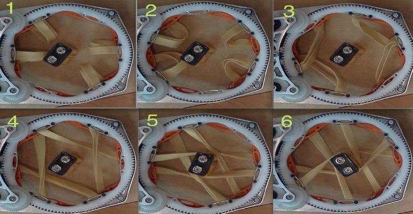
Geometric/CAD                                                                                         Delivery
               Input Data          Geometric                                     Dispatcher                       Robot (VI)
                                                      Ordered set of
                                 Preplanner (IV)                                    (VI)
                                                      Actions on
                                                      Parts
                                 ABPL                                                     Actions                Assembly
                                                                                                                 Robot (VI)
                                                                                Coordinated
                                    Symbolic
                                                                                Manipulation                      Assembly
                                   Planner (V)
                                                                                  (VIII)                            Robot
                                                                                                                with Tool (VII)

                       Fig. 2.   System architecture. The paper section describing each module is shown in parentheses.

system architecture for assembly of structures in orbit or for           Section VIII, we discuss the implementation of coordinated
planetary colonization. The authors also discuss a modular               manipulation involving multi-robot teams. Finally, in Sec-
tool changing system somewhat similar to our own. Heger                  tion IX we describe the demonstration of the complete
[4] describes a space assembly system that incorporates                  system for the assembly of an IKEA Lack table.
planning and execution, with an emphasis on error detection
and recovery. Neither geometric reasoning, nor multi-robot                                IV. G EOMETRIC P REPLANNING
coordination were a focus of this work.                                     The IkeaBot system begins the planning process by piec-
   In the furniture assembly domain, Spröwitz et al. [14]               ing together individual components based on their geometric
employ modular robots as smart parts to actually become                  description, similar to the work of Ambler and Popplestone
furniture using decentralized computation.                               [1], Thomas and Torras [17]. However, we extend that
   Rus et al. [13] discuss the conditions for a set of mobile            reasoning to output a blueprint for assembly comprising a set
robots (or fingers) to induce rigid body motions on an object,           of static coordinate transforms describing the final assembled
such as a piece of furniture, for manipulation purposes. These           position and orientation of each part as affixed to the others.
principles apply both to the manipulation of parts during                To uncover this information, the algorithm searches through
attachment (with fingers) and to the maneuvering of fully                possible subassemblies—that is, sets of one or more attached
assembled furniture.                                                     parts. In order to support future data acquisition by machine
                                                                         vision, a fuzzy match is performed between subassembly
         III. C OORDINATED A SSEMBLY S YSTEM
                                                                         pairs. For now, augmented CAD files are supplied by the
   The furniture assembly system uses several mobile manip-              user.
ulators capable of locating and connecting furniture parts.
For the physical experiments in this paper, the parts are                A. Representation
connected with screws, but the architecture and planning                    Geometry data take the form of a set of CAD files as well
systems support a general class of connectors.                           as a database specifying each hole in a part. As an example,
   The architecture for the furniture assembly system, de-               the geometric input file for the IKEA Lack table is shown
picted in Fig. 2, is organized into several modules that direct          in Listing 1. At present, these files are generated by hand,
the flow of information from basic geometric parts data into             but in the future they could be automatically generated from
an assembled piece of furniture. In the first stage, a geomet-           stereo vision or RGB+D data.
ric preplanning module solves for the configuration of the                  The input file provides a list of part types as well as the
completed furniture, based only on the form and quantity of              number of instances of each part. Since pegs or screws are
the individual parts—we describe the geometric preplanner                normally used to attach parts, the locations of these holes
in Section IV. The output of this first stage, a symbolic                within each part are key to understanding how the parts fit
blueprint, describes the final assembly configuration, but it            together. Consequently, most of the space in the input file is
does not provide an order of assembly. Consequently, the                 dedicated to their description.
blueprint is then fed into stage two, a symbolic planner                    Each part type is specified in the file by three fields.
discussed in Section V. This planner is capable of reasoning
                                                                            • file: the name of a CAD file describing the geometry
about available robots and parts. The symbolic planner out-
                                                                              (holes may be present or absent in the CAD data),
puts a sequence of operations that lead to a correct assembled
                                                                            • center: the approximate center of mass,
structure.
                                                                            • holes: a list of holes.
   In stage three, those actions are dispatched to individual
robots or teams of robots in sequence in order to execute                For each hole, three fields are required.
the task. The execution of assembly actions is described                    • diameter: either a number or the name of a fastener,
broadly in Section VI. We use a modular system of custom                    • position: the center of the hole in the surface plane,
tools to aid manipulation, as described in Section VII. In                  • direction: inward-pointing vector.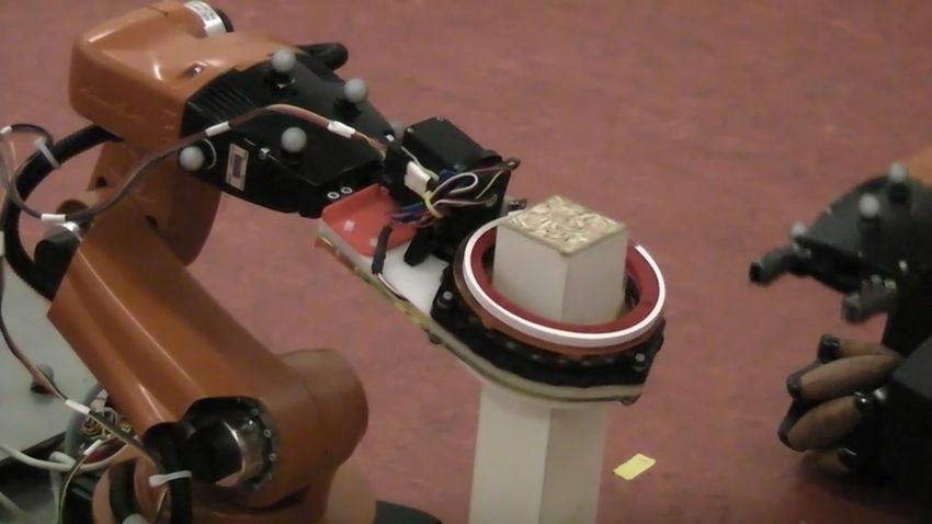
The center, position and direction fields are ex-                  Listing 1 Example input file for the geometric preplanner
pressed in part coordinates. Note that direction is speci-         describing parts for the the IKEA Lack table.
fied as an inward-pointing vector rather than a full orientation   parts: {table_top: 1, leg: 4}
                                                                   attach_parts: {double_screw: 4}
because the fasteners used here are radially symmetric,            hole_diameters: [0.006] # meters
allowing the parts to rotate around this axis with respect         attach_diameters: {double_screw: 0.006} # meters

to each other. An optional fourth field, pass through,             table_top: {
(absent in the example) applies to holes that pass fully             file: table_top.xml, # table is 0.551 x 0.551 x 0.050 m
                                                                     center: [ 0.28, 0.28, 0.025 ],
through the part and specifies the distance from position            holes: [ { diameter: double_screw,
along the direction vector before the exit hole is reached.                     position: [0.026, 0.026, 0.050],
                                                                                direction: [0, 0, -1] },
Such holes are usually attached by nails or conventional                      { diameter: double_screw,
screws. It is important for the geometric reasoning engine                      position: [0.525, 0.026, 0.050],
                                                                                direction: [0, 0, -1] },
to understand the correspondence between the two ends of                      { diameter: double_screw,
a hole because the assignment of one end removes the other                      position: [0.026, 0.525, 0.050],
                                                                                direction: [0, 0, -1] },
from future consideration as well.                                            { diameter: double_screw,
                                                                                position: [0.525, 0.525, 0.050],
                                                                                direction: [0, 0, -1] }
B. Relational Inference                                                     ]
                                                                         }
   At each step, the algorithm attempts to discover a coordi-
nate transform that will join two subassemblies together. One      leg: {
                                                                     file: leg.xml, # leg is 0.400 x 0.050 x 0.050 m
or more holes from each subassembly are used to propose              center: [ 0.200, 0.025, 0.025 ],
candidate transforms. Then, checks are performed to validate         holes: [ { diameter: double_screw,
                                                                                position: [0.0, 0.025, 0.025],
the candidate transforms before acceptance.                                     direction: [1, 0, 0] }
   The algorithm first selects a pair of holes—one hole                     ]
                                                                        }
each from two subassemblies—to associate. In joining two
holes, the algorithm computes a transform such that the two
subassemblies’ hole positions are coincident, thus reducing
the degrees of freedom by three. Furthermore, the holes
are oriented such that the direction vectors are parallel and      becomes unavailable for future use. Such free hole proximity
opposite, thus further reducing the freedoms by two.               queries as well as collision checks are performed using
   A pair of holes joined in this manner permits a single          OpenRAVE [3]. Part proximity to an unused hole creates a
degree of rotational freedom around the axis of the hole. To       penalty in the scoring function. A mating computed by hole
resolve the orientation, a second hole from each subassembly       matching and validated based on the above tests is considered
is chosen (if available) and one subassembly is rotated about      a plausible mating.
its hole’s axis so as to minimize error in lining up this second      The algorithm employs a number of tunable parameters
pair of holes. The minimum-error orientation resolves the          to score the quality of a mating of two subassemblies.
final degree of freedom and fixes a prospective transform          For geometry files generated by hand, the algorithm is not
for mating one subassembly to another. At this point, the          sensitive to the particular choice of values. For geometry
iterated closest point (ICP) algorithm is used to draw a           files obtained from perception data, it will likely become
correspondence among any remaining pairs of holes in the           necessary to learn a reasonable tuning of these parameters.
two subassemblies. The error in matching all pairs of holes
figures into an overall match score for the given transform on
these two candidate subassemblies. Closest holes separated         C. Search Algorithm
by more than a threshold value are not included in the match
and remain free for future use.                                       Search proceeds in a depth-first fashion through the space
   If one subassembly has only a single hole free, then there      of plausible matings of subassemblies. The algorithm is
are no other holes to help resolve the rotational ambiguity.       initialized with all components in a completely unassembled
In this case, an orientation is selected arbitrarily. Other        state. To begin the search, the algorithm instantiates the cor-
orientations can be tested until one is found that validates.      rect number of subassemblies, each representing a singular
   Several validation checks are employed to any proposed          instance of one of the basic parts.
subassembly transforms before they can be accepted. First,            During search, the planner exhaustively computes plausi-
the parts are collision-checked to verify that the proposed        ble mating transforms that lead to one or more holes lining
orientation of the two subassemblies does not lead to self-        up between adjacent parts. A plausible assembly has been
intersection. Minor penetration can occur due to imperfec-         found when two conditions are met: (1) all components are
tions in the model, thus incurring only a small penalty.           attached, and (2) no unfilled holes remain. Each plausible
More significant penetration invalidates a proposed mating         assembly is scored based on the scores of individual plausible
transform. An additional check examines the free holes not         matings. The highest-scoring plausible assembly is returned.
used in a particular mating operation. If a hole in one            The system utilizes this plausible assembly to construct a
subassembly is covered by another part, then that hole             blueprint for use by the symbolic planner.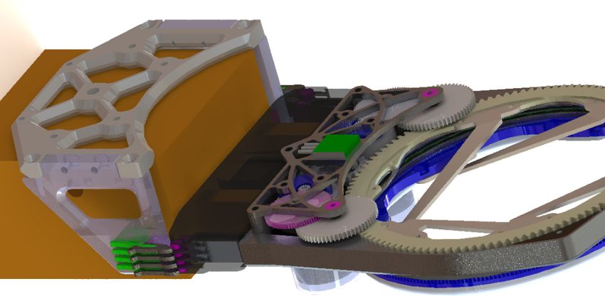
Listing 2 Machine-generated input file (blueprint) for the                   ABPL aims to overcome the necessary complexity of
symbolic planner, which builds an upright IKEA Lack table.                expressing object-oriented relations within first-order logical
type Robot {
    object arm {                                                          systems such as PDDL, the Planning Domain Definition
        property(Object) holding = None;
    }                                                                     Language [9]. PDDL relies entirely on a flat, unstructured
}
type AttachmentSpot {                                                     representation of the objects in the environment and the
    property(Object) attached_to = None;
}                                                                         relations between them. The burden of creating structure,
type TableTop {
    group hole(AttachmentSpot)[4]{}                                       such as regions of symbolic symmetry or commonalities
    property(bool) upside_down = True;
}                                                                         between multiple objects, falls entirely on the user. While
type Leg {
    object hole(AttachmentSpot){}                                         such systems are capable of describing OOP structures,
}
                                                                          requiring the user to express each element of those structures
object table_top(TableTop){}
group leg(Leg)[4]{}                                                       as a set of propositional statements would be time-consuming
group robot(Robot)[2]{}
                                                                          and burdensome to the user. ABPL, in contrast, allows the
action pick_up_leg(robot(Robot), leg(Leg)) {
    pre {                                                                 user to provide data in a more conventional object-oriented
        robot.arm.holding == None;
        leg.hole.attached_to == None;                                     format. An ABPL problem specification can be about one-
    }
    post {                                                                quarter the size of the equivalent PDDL specification. This
        robot.arm.holding = leg;
    }                                                                     simplicity improves readability and ease of ABPL problem
}
action attach_leg_to_top(robot(Robot), leg(Leg), table_top(TableTop)) {   creation, whether manual or automatic.
    pre {
        robot.arm.holding == leg;
        table_top.hole[0].attached_to == None;
                                                                          A. Specification Language Design and Structure
    }
    post {                                                                   ABPL is based on the object-oriented approach to data
        robot.arm.holding = None;
        table_top.hole[0].attached_to = leg.hole;                         structure design, allowing the user to hierarchically organize
        leg.hole.attached_to = table_top.hole[0];
    }                                                                     objects within the environment. Objects can be assigned
}
action flip_table(robot(Robot)[2], leg(Leg)[4], table_top(TableTop)) {    properties that evaluate to either Boolean values or references
    pre {
        leg[2].hole.attached_to == table_top.hole[1];                     to other objects. These values can be changed by the effects
        leg[3].hole.attached_to == table_top.hole[0];
        leg[0].hole.attached_to == table_top.hole[2];                     of symbolic actions to reflect those actions’ consequent
        leg[1].hole.attached_to == table_top.hole[3];
        table_top.upside_down == True;                                    alterations of the environment. Objects themselves can be
    }
    post {                                                                defined either at the top level in the global space, or as
        table_top.upside_down = False;
    }                                                                     sub-elements of other objects. These sub-object relations
}
                                                                          can be syntactically referenced in the same way as object-
goal assembly(table_top(TableTop)) {
    table_top.upside_down == False;                                       reference properties, but are semantically different in that
}
                                                                          their values cannot be changed after declaration. This fact
                                                                          is meant to convey the distinction between an object’s sub-
                                                                          objects, which represent fixed components of that object, and
                      V. S YMBOLIC P LANNING                              its object-typed properties, which represent mutable inter-
                                                                          object relations. ABPL also allows the user to define “types,”
   IkeaBot determines an order of operations for assembly
                                                                          which fulfill the role of object classes. A type can be assigned
using a symbolic planner. The planner attempts to discover
                                                                          properties and sub-objects, which are then replicated in each
an action sequence such that the preconditions of each
                                                                          object that is declared to be of that type. Types can also be
action are satisfied. The postconditions of an action support
                                                                          used as action and goal predicates, for example to restrict a
the preconditions of future actions, thus allowing progress
                                                                          symbolic action variable to values of a specific type.
toward the goal.                                                             An important distinction from other object-oriented sym-
   It should be noted that the symbolic planner ignores                   bolic planners is the inclusion of groups. Groups represent
the order in which the geometric preplanner discovered the                the existence of multiple identical instances of a given object.
mating of subassemblies. Rather, the symbolic planner relies              For example, Lack tables have four legs, declared simply as
only on the blueprint generated by the geometric preplanner               group leg(Leg)[4].
to identify the goal of the assembly. Assembly operations                    Groups enable the planner to reason efficiently about one
may require that components be assembled in a completely                  type of symmetry. Because the four legs are identical, they
different order than that previously discovered by static                 are interchangeable. Thus any leg can be attached to any
geometric analysis.                                                       corner of the table, and they can be installed in any sequence.
   Blueprints are specified using a newly-designed planning               When referencing a member of the group, it is sufficient to
language. ABPL (“A Better Planning Language”) is an                       reference the first member of that group. The planner knows
object-oriented symbolic planning specification language,                 that this rule extrapolates to all other group members as well.
exemplified in Listing 2. Conceptually similar to OPL [5],                Subsequently, one may reference the second group member
ABPL describes planning problem data in a manner which                    to indicate any table leg except the one already referenced.
respects the logical and intuitive features of the physical
environment as a planning space. ABPL enables an intuitive                B. ABPL Implementation for Assembly
statement of the problem by logically organizing concepts us-                IkeaBot’s planning module uses the ABPL specification
ing various object-oriented programming (OOP) paradigms.                  for its raw input and output data. At present, there is no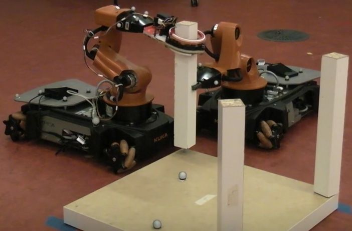
Problem Symbolic
                                Problem Text
  ABPL Problem Text                                    Environment               Problem Text           PDDL Problem Text
                                 Interpreter
                                                         Structure                Formatter
                                                                                                                                    Fast-Forward
                                                                                                                                   Symbolic Solver
                                                      Solution Symbolic          Solution Text
                                Solution Text
  ABPL Solution Text                                    Environment               Interpreter           PDDL Solution Text
                                 Formatter
                                                          Structure

Fig. 3. Symbolic planner architecture. At present, the planner converts ABPL into PDDL and executes the Fast-Forward solver. In the future, this process
(the large box at right) may be replaced with a direct ABPL solver that can incorporate algorithmic hooks and other features unavailable in PDDL.

symbolic solver that operates directly on ABPL. Rather, we                    Listing 3 Example input file (recipe) for the dispatcher to
convert symbolic data from one format to another using a                      construct the IKEA Lack table.
                                                                              step   pick_up_leg(robot[0], leg[1]);
three step process: a text interpreter (built using the SPARK                 step   attach_leg_to_top(robot[1], leg[1],         table_top);
little language framework [2]), a symbolic environment struc-                 step   pick_up_leg(robot[0], leg[3]);
                                                                              step   attach_leg_to_top(robot[1], leg[3],         table_top);
ture, and a text formatter. The process is outlined in Fig. 3.                step   pick_up_leg(robot[0], leg[2]);
A planning problem is passed through this process twice;                      step   attach_leg_to_top(robot[1], leg[2],         table_top);
                                                                              step   pick_up_leg(robot[0], leg[0]);
once to convert ABPL data into a PDDL format for use by                       step   attach_leg_to_top(robot[1], leg[0],         table_top);
the internal symbolic solver, Fast-Forward [6], and again to                  step   flip_table(robot, leg, table_top);
reformat the resulting solution sequence back into ABPL.
Alternatively, the calling program, such as the main IkeaBot
system, can retrieve the solution sequence in data structure
form rather than as ABPL solution text.                                       all assembly robots. Actions employ a fixed number of robots
    The current design of this planning program is predi-                     (one or two in our IKEA Lack table example) to one or more
cated on the assumption that any given planning problem’s                     subassemblies. Listing 3 shows an example ABPL-encoded
physical constraints can be expressed entirely symbolically.                  input to the dispatcher. In the work of Stein, et al., parts
As this is a significant limitation when working with the                     may be initially ineligible for installation, requiring that new
geometric constraints inherent to the physical domain, future                 parts get allocated to assembly robots during the course of
work includes the extension of ABPL’s grammar to allow                        assembly. Similarly, some actions may be initially unready
for external program calls out of the solver in order to                      for execution due to their preconditions. A partial ordering, if
incorporate non-symbolic data and logic into the planning                     available from the symbolic planner, informs the dispatcher
process. An important example is the use of a motion planner                  when each action becomes eligible for execution.
to determine when it is feasible to attach two subassemblies.                    In mobile manipulation, most actions require navigation
                                                                              and obstacle avoidance capabilities. IkeaBot achieves these
                  VI. A SSEMBLY E XECUTION                                    capabilities using the Model-Based Hierarchical Planner [8].
                                                                              It provides navigation through an environment cluttered with
   Furniture assembly is accomplished by a large set of small                 furniture parts and other robots. Navigating robots utilize a
manipulation actions, each executed by the right robot with                   sampling-based reciprocal algorithm to anticipate the reac-
the right part(s) at the right time. To orchestrate this activity             tion of other robots as well as human pedestrians.
among an arbitrary number of robots in a distributed fashion,
we utilize a modified version of the system described by
Stein et al. [15].                                                                                     VII. T OOL U SAGE
   In that system, a static blueprint describing part locations                  Some manipulation problems are best solved in hardware.
in an absolute frame of reference is passed to a partitioner                  In this section, we describe a modular system of hot-
(running on all assembly robots), which divides responsibil-                  pluggable, dockable tools that is designed to interface with
ity for installing each of the parts among the set of available               the KUKA youBot gripper and wrist design.
assembly robots. Meanwhile, a set of delivery robots stands
by, ready to retrieve and hand off the parts needed by the
                                                                              A. Interchangeable Gripper System
assembly robots for installation.
   We adapted this framework in order to increase its flexi-                     In order for the robots to use tools effectively, we designed
bility for the IkeaBot assembly problem. Specific challenges                  a system that allows tools to be quickly removed or replaced
we address are heterogeneous parts without fixed global co-                   with other tools. Manufacturing automation is replete with
ordinates, heterogeneous robot capabilities, and collaborative                existing systems for tool interchange at scales too large for
multi-robot manipulation activities.                                          the KUKA youBot. Our system allows a single robot to
   We replace the partitioner with a dispatcher, in recognition               accomplish a variety of manipulation activities autonomously
of the fact that the salient assignment is over actions rather                with compact tools, thus greatly increasing the functionality
than parts. The dispatcher remains a distributed process over                 of the robots.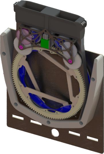
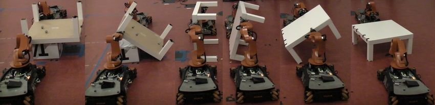
Fig. 6. A series of frames show the Torq gripper gripping and spinning
        Fig. 4.   The Torq gripper employed for table assembly.               an object.

Fig. 5. Solid modeler depiction of the screwing device. The powered upper
ring is shown in tan; the passive lower ring is blue. The black part on the
left is the coupling point to the KUKA youBot end-effector.

B. Torq Gripper Design                                                        Fig. 7.     The Torq gripper in its docking station. Due magnetic and
                                                                              gravitational force, the tool settles into a unique position.
   We designed a spinning gripper tool, the Torq Gripper,
which specializes in screwing-type operations. We observed
that the KUKA youBot arm, having only five degrees of                         contract around the object in the center as can be seen in
freedom, lacks the capability to rotate its wrist side-to-side.               Fig. 6. After a threshold torque is reached, the bottom ring
This limitation makes screwing operations very difficult.                     and the object begin to spin as well in a stick/slip fashion.
   Our design specification requires a versatile tool capable                    This design enables the rings to maintain an approximately
of applying high torque (up to 3 Nm) over many revolutions                    constant gripping force on the part. The gripping strength is
to a shape with either circular or non-circular cross section.                controlled by the combination of the elasticity of the cables
The new robotic gripper uses multiple elastic cables to                       and the force exerted by the magnets. Elasticity permits the
compliantly constrain and then spin an object, as in Fig. 4.                  tool to be non-destructive in its application of force, which
   A somewhat similar design was employed by Nguyen et al.                    is distributed almost uniformly around the circumference of
[10] in the design of the gripper for the Space Shuttle’s                     object. Additionally, the elastic nature of the force applica-
Canadarm manipulator. The Canadarm employs a set of                           tion permits considerable error in position and orientation
cables that constrict around a part as a snare. Our design                    during operation. More information about the Torq gripper
contributes two primary distinctions geared for the furniture                 and its design can be found in the work of Romanishin [12].
assembly task. First, the elasticity and resulting compliance                 Below, we describe the coupling mechanisms whereby the
of the cables allows the robot to handle uncertainty in the                   robot picks up and docks the gripper and other tools.
relative position and orientation of the part. Second, both                      1) Attachment to Robot Base: Figure 7 shows the system
ends of each cable connect to movable rings, which enables                    that has been designed to hold the Torq gripper on the robot
the device to easily rotate the part after it has been grasped.               body when not in use. The design takes advantage of the
   The Torq gripper functions by the encirclement of the                      magnets embedded in the unactuated ring, which attach the
target object with flexible elastic members. These members                    tool to a steel plate. The dock design guides the tool into a
are attached to two separate rings (see Fig. 5). The top ring                 unique rest state for later retrieval.
is driven by a pair of motors, whereas the bottom ring is                        2) Attachment to Robot Arm: When needed, the tool is
unactuated. The unactuated ring contains a set of magnets                     retrieved from its dock by pulling directly away from the
designed to increase the ring’s static friction. As the driven                steel surface. The tool is shown coupled to the KUKA
ring is spun by the motors, the elastic elements begin to                     youBot hand in Fig. 8. Eight magnets attract flexure-based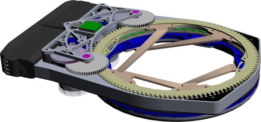
Grasp point

                                                                                                                       Final gripper
                                                                                                                         position

                                                                          Initial gripper
                                                                             position
Fig. 8. A model of the Torq gripper attached to the end of the KUKA                                                         Virtual hinge
arm. Magnetic contacts are shown at left.

steel electrical contacts in order to make the necessary power        Fig. 10.     The geometry of kinematic object flipping. Starting from
                                                                      an arbitrary grasp point, the gripper rotates 90◦ about a virtual hinge,
and data connections. These magnets serve an additional               maintaining a constant distance.
purpose of guiding the coupling into position. The KUKA
youBot gripper then securely grasps a custom handle located
inside the housing of the tool. An Arduino microcontroller               In order to compute the desired motion of the hand to
on the robot sends commands and interprets sensor signals.            kinematically flip an object, the robot tracks the position
                                                                      of the gripper with respect to the virtual hinge. The robot
           VIII. C OORDINATED M ANIPULATION
                                                                      computes the desired velocity of its own end-effector in
   For a variety of reasons, several robots must sometimes            Cartesian coordinates in order to track an arc. See Fig. 10.
come together in collaborative teams in order to complete the         Each robot adjusts the velocity of motion to match the other’s
overall assembly task. Some subassemblies may be too heavy            pace. Joint velocities are then computed via the Jacobian.
or large for a single robot to manipulate effectively, or more        Execution terminates after the grippers sweep through 90◦ of
robots may be required in order to fixture all of the parts           rotation (the normal case) or when joint limits or singularities
involved in a single attachment operation. In this section,           are reached. At present, the starting shape of the arm is
we address two issues of coordinated manipulation: dynamic            carefully selected by hand to avoid these kinematic failure
teaming and co-manipulation with decentralized coordinated            modes. In the future, this process will be automated.
control. An example of two robots cooperatively flipping a
table can be seen in Fig. 9.                                                         IX. H ARDWARE D EMONSTRATION
   We address the resource allocation issue of dynamic team-             We demonstrated the capabilities described in this paper
ing in a greedy manner. Each robot’s dispatcher allocates the         using two KUKA youBots, which assembled an IKEA table.
set of currently valid actions, including both single-robot and       Beginning from geometric descriptions of the parts, the
team actions. Assembly robots perform all part-attachment             robots automatically compute a blueprint and assembly plan.
actions that can be performed without help. Delivery robots              During execution, a Vicon motion capture system provides
receive no singleton assignments besides delivery tasks.              localization for the robots and the table-top, although the
However, delivery robots are eligible to participate as part          table legs are unmarked. Instead, table legs are available at
of a team when called upon to do so.                                  a fixed location in the global Vicon reference frame.
   Because it is harder to allocate multiple resources at once,          The robots expect the table-top to begin in the inverted
team activities take priority over singleton actions. After the       position, as indicated in the ABPL blueprint shown in
dispatcher recognizes that the preconditions for a team task          Listing 2. The robots can assemble the table flat on the
have been satisfied, the robots involved finish their current         ground or elevated on a platform. The latter condition, as
action and then proceed to perform the task in a coordinated          depicted in Fig. 9, assists the robots in flipping the IKEA
fashion.                                                              Lack table, whose weight exceeds the combined rated 1 kg
   Team actions frequently possess a compound nature, and             maximum load capacity of a pair of youBots.
so they are implemented as a state machine. For the ta-                  In addition to table assembly, the robots know how to
ble flipping example, states include coarse (global-frame)            make a stool or two-level table out of a pair of half-height
navigation, precision (part-frame) navigation, opening and            Lack tables by stacking one on top of another.
closing the gripper, and most importantly, following through             The overall runtime to fully assemble the Lack table is
the mechanics of a flipping motion.                                   approximately ten minutes. Of that time, virtually all is spent
   The flipping motion implements a virtual hinge at one              in execution. Geometric preplanning and symbolic planning
corner of the table and follows through 90 degrees of travel          consume only a few seconds each. The following list reports
at a time. At the conclusion of each 90-degree interval, the          approximate times involved in executing specific tasks as part
position of the virtual hinge is then updated to the next corner      of the assembly: pick up leg: 20 s, place leg in hole: 13 s,
before the action continues.                                          hand off leg: 6 s, screw in leg: 45 s, flip table: 50 s.
Fig. 9. This sequence of images shows the process by which two robots flip a table.
To test robustness of the implementation, we performed [6] J. Hoffmann and B. Nebel. The FF planning system: Fast
twelve repeated trials of the table assembly. Of those, nine plan generation through heuristic search. Journal of Artificial
were completely successful. In three trials, a screw missed Intelligence Research, 14:253–302, month 2001.
[7] L.S. Homem de Mello and A.C. Sanderson. A correct and
the hole. Once, the screwing device failed due to software. In complete algorithm for the generation of mechanical assembly
all, we observed 48/48 successful pickups, 44/48 successful sequences. IEEE Transactions on Robotics and Automation,
placements, and 47/48 successful attach operations. Minor 7(2):228–240, April 1991.
human assistance permitted all trials to run to completion. [8] R.A. Knepper and D. Rus. Pedestrian-inspired sampling-based
multi-robot collision avoidance. In Proceedings of the IEEE
X. D ISCUSSION AND F UTURE W ORK International Symposium on Robot and Human Interactive
Communication, Paris, France, September 2012.
In this paper, we describe an implementation of a furniture [9] D. McDermott, M. Ghallab, A. Howe, C. Knoblock, A. Ram,
assembly system. Parts of the planning system are quite gen- M. Veloso, D. Weld, and D. Wilkins. PDDL—the plan-
eral in capability, such as planning “from scratch” with only ning domain definition language. Technical Report CVC
the geometric form of the components as input—not even TR98003/DCS TR1165, Yale Center for Computational Vi-
sion and Control, New Haven, USA, 1998.
their assembled shape. We introduce a new language that [10] P.K. Nguyen, R. Ravindran, R. Carr, D.M. Gossain, and
is intuitive for humans and robots that efficiently expresses K.H. Doetsch. Structural flexibility of the shuttle remote
symbolic planning problems. We describe a modular system manipulator system mechanical arm. Technical report, SPAR
for powered tool use by the KUKA youBot. We discuss a Aerospace Ltd., 1982.
distributed task allocation system for a team of robots that is [11] J. Latombe R.H. Wilson. Geometric reasoning about mechan-
ical assembly. Artificial Intelligence, 71:371–396, 1994.
capable of dynamically reassigning tasks as needed, subject [12] J. Romanishin. Development of a robotic torque application
to the capabilities of each robot, demonstrated through the gripper for automated furniture assembly, 2012. Undergradu-
assembly of an IKEA Lack table. Finally, we discuss an ate Thesis.
approach to multi-robot coordination for co-manipulation, [13] D. Rus, B. Donald, and J. Jennings. Moving furniture with
illustrated through the flipping of the table. teams of autonomous robots. In Proceedings of the IEEE
International Conference on Intelligent Robots and Systems,
Future work primarily revolves around making the system August 1995.
more generic. We plan to generalize the implementation of [14] A. Spröwitz, P. Laprade, S. Bonardi, M. Mayer, R. Mckel,
symbolic actions for manipulation to broaden the variety of P. Mudry, and A. Ijspeert. Roombots-towards decentralized
furniture kits the system can assemble. We also intend to reconfiguration with self-reconfiguring modular robotic meta-
modules. In Proceedings of the IEEE International Confer-
generalize the collaboration framework to achieve a variety
ence on Intelligent Robots and Systems, IEEE International
of co-manipulation tasks besides object-flipping. Finally, Conference on Intelligent Robots and Systems, pages 1126–
failure detection and recovery will be added for robustness. 1132, Taipei, Taiwan, 2010.
[15] D. Stein, T.R. Schoen, and D. Rus. Constraint-aware coor-
R EFERENCES dinated construction of generic structures. In Proceedings of
[1] A. P. Ambler and R. J. Popplestone. Inferring the positions the IEEE International Conference on Intelligent Robots and
of bodies from specified spatial relationships. Artificial Intel- Systems, 2011.
ligence, 6:157–174, 1975. [16] A.W. Stroupe, T. Huntsberger, B. Kennedy, H. Aghazarian,
[2] J. Aycock. Compiling little languages in python. In Proceed- E.T. Baumgartner, A. Ganino, M. Garrett, A. Okon, M. Robin-
ings of the 7th International Python Conference, 1998. son, and J.A. Townsend. Heterogeneous robotic systems for
[3] R. Diankov. Automated Construction of Robotic Manipulation assembly and servicing. In Proceedings of the International
Programs. PhD thesis, Carnegie Mellon University, Robotics Symposium on Artifical Intelligence, Robotics and Automation
Institute, August 2010. in Space, Munich, Germany, August 2005.
[4] F.W. Heger. Assembly Planning in Constrained Environments: [17] F. Thomas and C. Torras. Inferring feasible assemblies
Building Structures with Multiple Mobile Robots. PhD thesis, from spatial constraints. IEEE Transactions on Robotics and
Carnegie Mellon University, Robotics Institute, August 2010. Automation, 8(2):228–239, 1992.
[5] A. Hertle. Design and implementation of an object- [18] R.H. Wilson. Minimizing user queries in interactive assembly
oriented planning language. Master’s thesis, Albert-Ludwigs- planning. IEEE Transactions on Robotics and Automation, 11
Universität Freiburg, 2011. (2), April 1995.You can also read