INSTALLATION INSTRUCTIONS INSTALLATION INSTRUCTIONS - SIRIUS CAPPE
←
→
Page content transcription
If your browser does not render page correctly, please read the page content below
INSTALLATION INSTRUCTIONS
INSTALLATION INSTRUCTIONS
CARE AND USE MANUAL FOR:
NOTICE D’UTILISATION ET D’ENTRETIEN POUR:
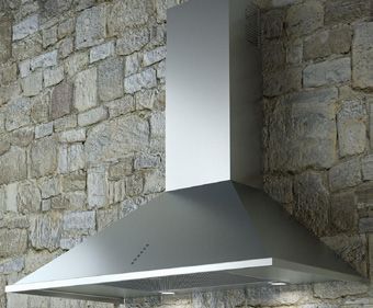
WALL RANGE HOODS
HOTTES MURALES
Models covered by this instructions - Notice d’instruction pour les modèles:
SU1 - SUE1 - SU2 - SU3 - SUE3 - SU10 - SU22
SU92 - SUTC92 - SU54
*** BEFORE INSTALLATION ***
ENSURE THERE IS NO VISIBLE OR HIDDEN DAMAGE SUSTAINED DURING SHIPPING
*** AVANT L’INSTALLATION ***
S’ASSURER QUE LES PRODUITS N’ONT SUBI AUCUN DOMMAGE PENDANT LE TRANSPORT
*** SHIPPING DAMAGE ***
MUST BE REPORTED WITHIN 5 DAYS OF RECEIPT
*** DOMMAGES DE TRANSPORT ***
DOIVENT ÊTRE NOTIFIÉS DANS LES 5 JOURS SUIVANT LA RÉCEPTION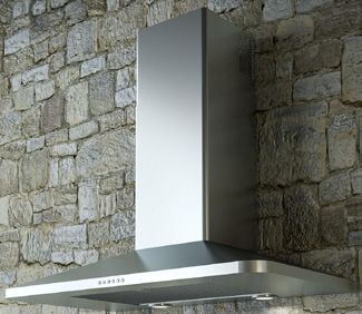
WA R N I N G

      Thank you for purchasing a Sirius Range Hood.
    Please read all the instructions in this manual before
                  installing the appliance.

           Save these instructions for future reference.

Only use this appliance as an exhaust ventilation system for the removal of coo-
king vapors. DO NOT use to expel flammable substances or any other materials
or vapors.

The installation procedures in this manual are intended for qualified installers, ser-
vice technicians or persons with similar qualified background.
DO NOT attempt to install this appliance yourself.

Ensure that electrical power is turned off at source before commencing installation.
All electrical wiring must be properly installed, insulated and grounded and conform
to all applicable codes and standards.

Make sure all existing duct work is clean of grease build up, or duct work should be
replaced, if necessary, to avoid the possibility of a grease fire. Check all joints on
ductwork to ensure proper connection and all joints should be properly taped. Be
careful when cutting through ceilings or walls not to damage any hidden pipes or
electrical wiring. Ensure your kitchen has sufficient air return vents to replace the
exhausted air.

Fan ducts should always be vented to the outside of your home and never into
spaces within walls, ceilings, lofts or attics. Only use rigid, smooth steel for ducting.
The exhaust point of the blower requires a 6” round or 8” connection.

                                           2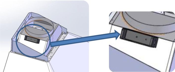
TABLE OF CONTENTS

BEFORE YOU BEGIN                              4

DUCTING                                       4
External Venting Requirements                 4
Duct Run Calculation                          4

ELECTRICAL                                    5
Electrical Supply                             5

INSTALLATION                                  6
Positioning the Range Hood                    6
Marking the Fixing Holes for the Range Hood   6
Fixing the Main Support Bracket               6
Chimney installation                          8
Hanging the Range Hood                        8
Connecting Electricity and Ducting            8
Connecting Chimneys                           9
Re-Circulating Requirements                   10

OPERATING PROCEDURES                          11
General Advice                                11
Functions                                     11

MAINTENANCE                                   14
Cleaning the Filter                           14
Cleaning the Hood                             14
Substitution of the LED bar                   15

WARRANTY SERVICE                              16

                                       3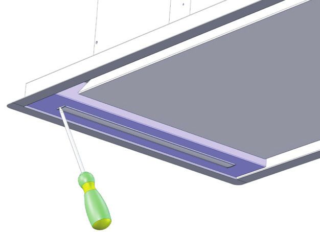
BE F O R E Y O U B E G I N
The manufacturer declines all responsibility          BEFORE YOU BEGIN: It is advisable to test
in the event of failure to observe the instruc-       run the range hood before installation.
tions given here for installation, maintenan-
ce and suitable operation of the product. The         BEFORE STARTING – please read this
manufacturer further declines all responsibi-         entire document and ensure you are fully
lity for injury due to negligence and the war-        conversant with the require-ments and li-
ranty of the unit automatically expires due           mitations. These units weigh approximately
to improper maintenance and/or installation.          125lbs and therefore require a minimum of
                                                      two people to install.

                                    DUCTING
(Not applicable if the range hood is used in          Only use rigid type metal ducting (plastic duc-
recirculing model)                                    ting is generally not permit-ted by code). Flexi-
                                                      ble ducting could restrict airflow by up to 50%.
WARNING: Do not vent this appliance into              Always fasten connections with sheet metal
any other ductwork, spaces between walls,             screws and tape all joints with certified Silver
ceilings, attics, garages or any other confi-         Tape or Duct Tape.
ned space.
                                                      Do not use screws to fasten ductwork to the
External Venting Requirements.                        hood, only use tape as the screws will stop the
When planning new ductwork, always look               dampers from opening and your hood will not
for the most direct route to the outside. Ven-        work. This hood requires a 6” round duct outlet
ting can be done through the roof or directly         for the models with 1 motor, and 8’’ for the mo-
through the back outside wall. (See Figure            dels with 2 motors. You can increase the duct
1). Recommanded 18” from the top of the               size of the duct run but never decrease it.
hood to the first elbow.
                                                      Use the shortest and most direct route possi-
                                                      ble. Always, wherever reduce the number of
                                                      transitions and turns with as few sharp angles
                                                      as possible.

                                                      Two staggered 45 degree angles are better
                                                      than one 90 degree. Make these turns as far
                                                      away from the motor exhaust as possible, with
                                                      as much space between each bend as possi-
                                                      ble.

                                                      Duct Run Calculation
                                                      The maximum duct run before effecting the
                                                      performance of the hood is 100’. Calculate your
                                                      duct run by measuring linear feet and adding
                                                      the elbows, transitions and caps based on the
                                                      table alongside.
fig. 1

                                                  4
Maximum Run
  6” or 3 1/4 x 10” duct *           100 FT

  Deduct

  Each 90 elbow used                 15FT

  Each 45 elbow used                 9FT

  Each 6” or 3 1/4 x 10” duct

  Transition used                    1FT
                                                       fig. 2
  Each 3” 1/4 x 10” to 6”

  Transition used                    5FT               Range hoods may interrupt the proper flow of
                                                       combustion gases from fireplaces, gas furna-
  Side Wall with damper              30FT              ces and gas water heaters.
  Roof Cap                           30FT
                                                       To minimize the risk of drawing these lethal
                                                       gases back into the home, please follow the
* Gas range or gas cook top recommanded 8”.
                                                       heating equipment manufacturers safety
                                                       standards and guidelines carefully.
The ducting connection to the hood must be in
line with the central vertical axis of the range
                                                       Refer to NFPA and ASHRAE for additional
hood 1” away from the back wall on which the
                                                       information.
hood is to be mounted. The 1” is important to
enable the ceiling bracket (as shown in Figure
2) to pass behind the ductwork servicing the
range hood.

                                ELECTRICAL
WARNING: All electrical work must be                   Electrical Supply.
performed by a qualified electrician.                  This range hood requires a 120V, 60Hz sup-
                                                       ply and draws a maximum of 3 amps. The
Please ensure that the appropriate electrical          electrical supply to the range hood should be
codes or prevailing local building codes and           at least 17” from the underside of the instal-
ordinances are adhered to.                             led range hood.

Ensure that the electricity supply is discon-          The cooking surface and the lower part of the
nected at source. Do not use an extension              cooker hood must be at a minimum distance
cord or adapter plug with this appliance.              of 65 cm from one another.
                                                       The instructions given in the user manual of
This appliance must be grounded. Connect               the hob are to be taken into full consideration.
to a properly grounded branch circuit, pro-
tected by a 15 amp circuit breaker.

                                                   5
I N S TA L L AT I O N
Positioning the Range Hood.                              Using a sharp object, mark the wall through
Determine the center point of the range hood.            the template at the center point of the three
This is generally the center of the range. Make          holes. Lower down on the template, you will
a mark on the wall a minimum of 25” above                see three sets of two holes. Only two of these
the top of an electric range. If the range is gas,       holes refer to your model. Check which mo-
the ideal minimum should be 30”.Using a spirit           del you have and, using a sharp object, mark
level, draw a perfectly vertical line, starting at       the two correct holes. These holes are used
the center mark, right up to the ceiling or the          to anchor the range hood horizontally from in-
highest point to where the hood will extend.             side the hood once it has been hung from the
This is the central axis for the range hood.             main bracket. Remove the template.
Draw a horizontal line fractionally above whe-
re the bottom of the range hood will be positio-         Fixing the Main Support Bracket
ned. This is the underside of the range hood.            (CAUTION: Do not drill through any utili-
                                                         ties inside the wall).
Marking the Fixing Holes for the Range
Hood.                                                    If the range hood will be fixed to drywall we
Find the marking template provided called                strongly recommend that you discard the wall
the “Assembly Scheme”. Place the template                plugs and screws supplied. These anchors are
against the wall. Align the horizontal line on           only suitable for brick/masonry applications. We
the wall with the horizontal line on the tem-            suggest the use of a more appropriate anchor
plate (indicated by two heavy arrows). Now               system specifically designed for drywall applica-
align the vertical line on the wall with the             tions. Wherever possible, it is advisable to place
“Central Axis” line on the template.                     blocking between the studs, behind the drywall,
                                                         to attach the support bracket to, (refer to Figure 4).

                                                         fig. 4
fig. 3
                                                         Drill the appropriate size holes at the marks
Gently tape the template to the wall making              made earlier and fix the Support Bracket (“S”)
sure it has no creases or folds (use a tape              securely to the wall. Ensure that any wall an-
that will not damage the wall finish). There             chors have been fitted into the lower two ho-
are three hole positions shown for the wall              les, as the range hood will cover these holes
bracket.                                                 once hung on the Support Bracket (“S”).

                                                     6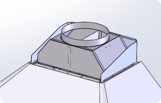
Before installing the hood is necessary to        And fix the box to the just-fit union with two
fix the tow motor air outlet union with the       screws.
screws that are in the accessory bag.

Then open the upper cover of the power
box.

                                              7
Chimney Installation.                                  The bracket fixed onto the back of the range
Locate the bracket (Fig. 2Y) and position              hood will drop into the channel on the top of
it with the vertical axis (marked on the wall          bracket “S” on the wall. Ensure the hood is
earlier) running through the midpoint of bra-          securely engaged into the support bracket
cket “Y”. This bracket fits onto the ceiling           -the range hood must clip in behind the ex-
and onto the wall to secure the upper half             tended lip on the Support Bracket (“S”).
of the decorative chimney in place. Mark the
wall for the two anchors and mark the ceiling          “Lock” the range hood onto the “S” bracket
for the two anchors as indicated in Fig. 2.            using the four machine screws supplied (re-
                                                       fer to Figure 7).
Fix bracket “Y - Fig.2” to the wall and ceiling.

Hanging the Range Hood.
Prepare the range hood for installation. Re-
move all filters to ensure they do not get da-
maged during the installation process. Hang
the range hood on the bracket “S” (refer to
Figure 6).

                                                       fig. 7

                                                       These screws are also used to make minor
                                                       adjustments to the levelling of the range
                                                       hood. Ensure the hood is level. Locate the
                                                       two holes “C” inside the housing of the range
                                                       hood and secure the range hood to the wall
                                                       once the range hood is perfectly level and
                                                       vertical. (refer to Figure 3).
fig. 6
                                                       Connecting Electricity and Ducting.
                                                       Please refer to the Electrical Supply section
                                                       on page 2 for the required location of the
                                                       electrical supply.

                                                       CAUTION: Make sure the power is turned off
                                                       at source. Make electrical connections (refer
                                                       to Figure 8).

                                                       Ensure that the plastic flaps at the exhaust
                                                       outlet for the fan move freely and have not
                                                       become jammed or stuck.

                                                   8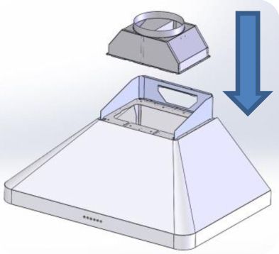
fig. 8

                                                      fig. 10
Connect the appropriate length of ducting
to the fan exhaust point and join up with the
ducting to the exterior.                              Do not fix the ducting to the range hood
                                                      exhaust outlet with screws-use duct tape.
Figure 9 shows venting directly through the           Use duct tape on all joints.
wall. Venting up and through the ceiling to the
exte-rior is also possible (refer to Fig 10).         Connecting Chimneys
                                                      Remove the protective covering from the
                                                      decorative chimney and carefully slide the
                                                      sections together. Do not remove the tape
                                                      strips from inside the chimney as this pro-
                                                      tects the telescoping chimney-piece from
                                                      scratching. Holding the two chimney sec-
                                                      tions together carefully position them over
                                                      the ductwork and wiring. Position the upper
                                                      chimney so that it can be fixed via the holes
                                                      on the side of the ‘Y” bracket on the ceiling
                                                      (refer to Figure 11).

fig. 9

                                                  9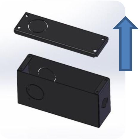
fig. 12

fig. 11

Re-Circulating Requirements.
If the unit is to be used in the re-circulating
mode, fit the carbon filter after the installa-
tion is complete (refer to Figure 12) fit the
deflector (refer Figure 13) with the screws
supplied to the upper telescope chimney.
There are holes in the back upper edge of
the decorative chimney for this purpose. A             fig. 13
short length of ducting is connected betwe-
en the exhaust outlet on the fan and the de-
flector to direct the air back into the kitchen
through the vents at the top of the upper de-
corative chimney.

The carbon filter (supplied separately) that
absorbs odors is installed behind the alumi-
nium grease filter (refer to Fig 14).

                                                       fig. 14

                                                  10
OPER AT I N G P R O C E D U R E S
Read all the instructions before operating FUNCTION
the appliance. Save these instructions for
future reference. “SU Models Manual touch buttons Fig. 15”
General Advice. A: Light ON/OFF button
Ensure that the grease filters are in place. B: Blower Speed 1 (low) or OFF
Without these components, operating blo- C: Blower Speed 2 (medium)
wers could catch on to hair, fingers and lo- D: Blower Speed 3 (high)
ose clothing. E: Blower Speed 4 (intensive)
F: 10 Minute Timer
Keep fan, filters and surfaces clean of gre-
ase and fat. Always turn hood fan ON when
cooking. NEVER leave cooking unattended.
NEVER dispose cigarette ashes, ignitable
substances or any foreign objects into blo-
wers.
fig. 15
Cooking that generates flame is not recom-
mended as this hood is equipped with a
thermal overload that will shut down the mo- “SUE Models Fig. 16”
tor if it senses excessive heat. When frying,
oil in the pan can easily overheat and ignite. A: Light ON/OFF button
Heat oil slowly in an appropriately sized pot B: Blower Speed 1 (low) or OFF
(covering the entire burner) to reduce the C: Blower Speed 2 (medium)
risk of boiling over and burning. D: Blower Speed 3 (high)
E: Hood in operation light
In the event of a range top grease fire, ob-
serve the following:
Switch OFF the range hood. Turn off the
cook top then smother flames with a close
fitting lid, cookie sheet or other metal tray. If
the flames do not go out immediately.
EVACUATE AND CALL THE FIRE DE- fig. 16
PARTMENT.
Never pick up a flaming pan – you may be
burned. DO NOT USE WATER including
wet dishcloths or towels, as a violent steam
explosion may occur.
11TC models (SUTC92) RC001
A: Light switch On/Off RADIO CONTROL
B: Reduce speed Radio control used for the remote operation of
C: Luminous telltale ducted cooker hoods.
D: Increase speed
E: 10 - minute timer TECHNICAL DATA
- Alkaline battery powered: 12 V mod. 27A
- Operating frequency: 433.92 Mhz
The touch control key allows the function de- - Combinations: 32.768
sired by touching the relative key. - Max. consumption: 25 mA
If the electrical power supply to the product - Operating temperature: -20 ÷ + 55 °C
SUTC is cut, 15 seconds are needed for sel - Dimensions: 130 x 45 x 15 mm.
fdiagnostics after the functions are restored.
Meanwhile, its operation may be incorrect. OPERATING DESCRIPTION
The products are endowed with an electronic The transmitter is equipped with 5 buttons for coo-
ker hood management, as specified below:
device which allows the automatic switching
off after 4 hours from the last operation.
: Light ON/OFF command.
: Motor ON (speed level 1) / OFF command.
: Reduce speed.
: Increase speed.
: 10-minute timer.
INITIAL OPERATING CONDITION
The manufacturer supplies the radio control unit
fig. 17 ready to be used with codes preset in the Factory
OPERATION MODE
Standard configuration:
Standard configuration requires all “cooker hoods
- radio control - system” to be provided with the
same transmission code. In the event two cooker
hoods - radio control system are installed in the
same room or nearby, each system may affect the
operation of the another. Therefore, the code of
one radio control system must be changed.
12Generating a new transmission code:
WARNING
The radio control system is provided with preset
The battery should be replaced every year to
codes. Should new codes be required, proceed
guarantee the optimal range of the transmitter.
as follows: Press simultaneously buttons:
To replace the exhausted battery, take the pla-
stic lid off, remove the battery and replace it
with a new one, observing the correct battery
polarities.
for two seconds. When Leds light on, press but-
Used batteries should be discarded in special
tons:
collection bins.
The below product:
(within 5 seconds). Leds flashing 3 times indicate
RC001 Radio Controll
the procedure is completed.
complies with the specifications set out in the
Directive RED 2014/53/EU.
WARNING! This operation deletes permanen-
tly the preset codes.
WARNING
Learning the new transmission code:
Any adjustments or modifications which have
Once the transmission code is changed in the ra-
not been expressly approved by the holder of
dio control unit, the electronic central unit of the
the legal conformity certificate may invalidate
cooker hood must be made to set the new code in
the user’s rights relating to the operation of
the fol- lowing way:
the device.
Press the main power-off button of the hood and
then restore power to the electronic control unit.
Within the next 15 seconds, press the Liight But- The products are endowed with an electronic de-
ton to synchronise the central unit with the vice which allows the automatic switching off after
code. 4 hours working from the last operation.
Reset of the Factory configuration:
To restore the Factory configuration, follow the
procedure described below: press simultaneously
buttons:
for 2 seconds. When Leds light on, press buttons:
(within 5 seconds). Leds flashing 6 times indicate
the procedure is completed.
WARNING! This operation deletes permanen-
tly the preset codes.
Emergency button:
In the event that the radio control does not work,
use the emergency button to switch the appliance
off. After any necessary repairs have been perfor-
med, reset the emergency button.
13SU Models only: Filter requires washing in- Use the low speeds for normal use and the
dicator After 30 hours of use, all the buttons higher speeds for strong odors and fumes.
will light up to remind you that the grease fil-
ter should be cleaned. Follow the instructions
for cleaning filters in this booklet. Once the
grease filters have been cleaned and repla-
ced, reset by pressing the timer button (F).
Do not rely solely on this indicator – general-
ly, the grease filter should be washed on a
regular basis to avoid grease filter fires.
The blower should be turned on for appro-
ximately 5 minutes before cooking in order
to establish air currents upward through the
hood.
M A I N T E N A NC E
The range hood should provide many years Cleaning the Hood
of trouble free use provided it is properly The outside and interior of your hood should
maintained. Be sure the lights are cool befo- be wiped regularly with a clean, damp cloth
re cleaning the hood - they are halogen and and mild household dish detergent or degre-
become extremely hot. aser.
Cleaning the Filter. Use a good quality non-abrasive foaming
The aluminium mesh filters should be wa- type stainless steel cleaner for exterior sur-
shed by hand or in the dishwasher as re- faces.
quired. Damaged and worn filters must be
replaced immediately. (Do not operate blo- Follow the manufacturers directions. Gene-
wer when filters have been removed). Allow rally the foam is sprayed onto a clean dry
filters to dry before replacing them, otherwi- cloth and then applied to the stainless steel.
se water will be drawn into the blower. Allow the foam to react on the surface for a
few minutes and then wipe with a clean dry
If a carbon filter has been fitted, this must be cloth.
replaced every 6 months as a minimum, de-
pending on usage and type of cooking that On the surfaces that are exposed directly to
is performed. heat from the cook-top, it is advisable to cle-
an these regularly to avoid the deposits from
It is suggested that a spare set of carbon becoming baked on.
filters is kept on hand. These can be ordered
from the supplier of your range hood. Do not use abrasive cleaning agents as the-
se will destroy the brushed finish.
14(If in doubt, call 866.528.4987) FOR SU92
Substitution of the LED bar:
FOR SU1 – SUE1 - SU2 - SU3 - SUE3 - Using an appropriate tool, remove the LED
SU10 - SU22 - SU54 bar from its seat (refer to Fig. 21), disconnect
it electronically using the appropriate con-
To replace the round LED lamps (fig.20) you nector then substitute it with a LED bar with
have to check first if it is possible to access same characteristics.
the back side of the lamp with your hand.
If it is possible to access the back side of the
lamp, you have to: insert your hand , push at
the same time both support wings of the
lamp, push to remove the lamp.
If it is not possible to access the back side of
the lamp, you have to: provide yourself with
a sharp utensil, insert the utensil between the
lamp and the stainless steel frame (on the
side where the little support wings are pla
ced), push to remove the lamp from the coo
ker hood.
fig. 20
fig. 19
15YOU MUST REGISTER THE PURCHASE OF YOUR PRODUCT ON LINE AT HYPERLINK
“http://www.siriuscappe.com/canada/warranty.htm” TO CONVALIDATE YOUR WARRANTY.
YOU CAN FIND THE DATA OF YOUR HOODS ON A LABEL INSIDE THE HOOD. JUST REMOVE
THE GREASE FILTER TO READ IT.
WARRANTY SERVICE
To qualify for warranty service, you must notify Sirius After sale service at the email address
stated below or call toll free in Canada 1-800-463-2566 and provide the model number, de-
scription of the fault or defect and original date of purchase. Sirius reserves the right to re-
quest proof of original purchase. Sirius will at its sole option and discretion replace products
that arrive damaged through shipping, provided shipping damage is reported as stated above
within 5 business days of receipt of the shipped product or products.
ONE YEAR PARTS & SERVICE REPAIR WARRANTY:
During the first year from date of original purchase, Sirius will, at its option, repair or replace, without
charge, any product or part which is found to be defective under normal use and service.
WHO IS COVERED:
Sirius Range Hoods warrants to the original consumer purchaser of its products that such products will
be free from defects in materials and workmanship for a period of one year from the original date of pur-
chase. There are no other warranties, express or implied, including, but not limited to, implied warranties
of merchantability or fitness for a particular purpose or application.
WHAT IS NOT COVERED:
This warranty does not extend to filters, lamps, batteries, ducts and ductwork components. This war-
ranty does not cover normal maintenance and service or products or parts which have been subject to
misuse, negligence, accident, improper maintenance or repair, faulty installation or installation contrary
to recommended installation instructions. The warranty on glass screens is limited to manufacturing
defects only and expressly excludes cracks and breakages as a result of faulty installation. Labor and
associated costs associated directly with removal and re-installation are expressly excluded.
The duration of any implied warranty is limited to the one year period as specified for the express war-
ranty. Some states and provinces do not allow limitation on how long an implied warranty lasts, so the
above limitation may not apply to you.
For any service request please contact:
Sirius after sale service
Telephone (toll free):1-800-463-2566.
Sirius S.P.A.
Zona industriale Berbentina 6/A
60041 SASSOFERRATO (AN)
ITALY
Register Online! www.siriuscappe.com/canada/warranty.htmINSTRUCTIONS IMPORTANTES
POURLA SÉCURITÉ
Merci d’avoir choisi une Hotte de Cuisine Sirius.
Veuillez lire attentivement toutes les instructions avant
l’installation et l’utilisation de l’appareil.
Conservez ces instructions afin de pouvoir les
consulter au besoin.
Cet appareil est destiné à la ventilation générale seulement. NE L’UTILISEZ PAS
pour évacuer des vapeurs ou des substances dangereuses ou explosives.
Confiez l’installation et les réparations uniquement à un professionnel, conformé-
ment aux normes de sécurité en vigueur.
N’ESSAYEZ PAS d’installer cet appareil par vous-même.
Avant l’installation veillez que l’appareil soit hors tension.
Tout le câblage électrique doit être correctement installé, isolé de mise à la terre
conformément aux codes et aux normes applicables.
Assurez-vous que les conduits d’évacuation sont propres et libres d’accumulation
de graisses ou remplacez les conduits pour éviter de provoquer un incendie.
Vérifiez que tous les joints du conduit sont bien fixés et scellés. Faites attention
lors des travaux de maçonnerie de ne pas endommager des tuyaux ou câbles
électriques. Assurez-vous que votre cuisine est équipée de bouches de ventilation
qui évacuent l’air vicié.
Le conduit de ventilation doit toujours terminer à l’extérieur et jamais dans des
espaces clos, plafonds ou greniers. Pour le conduit utilisez seulement des élé-
ments rigides en acier lisse.
La sortie de la soufflante nécessite d’un conduit rond de 6”. Ou Huit pouces (ou 8’’).
17TABLE DES MATIÈRES
AVANT DE COMMENCER 19
CONDUIT 19
Version Évacuation Extérieure 19
Calcul Longueur Conduit 19
ÉLECTRICITÉ 20
Alimentation Électrique 20
INSTALLATION 21
Positionnement de la Hotte 21
Perçage du Mur pour le Positionnement de la Hotte 21
Fixation Étrier de Support Principal 21
Installation de la Cheminée 23
Accrochage de la Hotte 23
Branchement Électrique et Conduit 23
Raccordement de la Cheminée 24
Mode Recyclage 25
PROCÉDURES D’UTILISATION 26
Recommandations Générales 26
Fonctions 26
ENTRETIEN 29
Nettoyage des Filtres 29
Nettoyage de la Hotte 29
Replacement de la barre LED 30
GARANTIE 32
18AVAN T D E C O M M E N C E R
Le fabricant décline toute responsabilité AVANT DE COMMENCER : On conseille de
en cas de dommages causés par un non vérifier le fonctionnement de la hotte avant
respect des instructions d’installation, d’uti- son installation.
lisation et d’entretien contenues dans cette
notice. Le fabricant décline toute responsa- AVANT DE COMMENCER – Lisez attentive-
bilité causée par négligence et la garantie ment cette notice afin d’avoir les connaissan-
cesse automatiquement en cas de mauvais ces requises pour utiliser ce produit. Ce pro-
entretien et/ou installation du produit. duit pèse env. 125lbs et nécessite donc un
minimum de deux personnes pour son instal-
lation.
CONDUIT
(Ne s’applique pas si la hotte est en mode Utilisez seulement des tuyaux rigides en métal
Recyclage). (les tuyaux en plastiques sont interdits par le
code).
Les conduits flexibles limitent le flux d’air du 50%.
REMARQUE: Ne branchez jamais ce pro-
Fixez toujours les raccords avec des vis en tôle et
duit à un autre conduit d’évacuation, des isolez tous les joints avec du ruban adhésif métal-
espaces entre deux murs, plafonds, gre- lique (ou pour conduit).
niers, garages ou espaces clos.
N’utilisez pas des vis pour fixer le conduit à la
Version évacuation extérieure. hotte; utilisez uniquement du ruban adhésif, du
Lors du montage du conduit d’évacuation, moment que les vis peuvent empêcher l’ouverture
cherchez la voie la plus directe vers l’ex- des clapets anti retour et en ce cas la hotte ne
fonctionnera pas.
térieur. Le conduit peut évacuer l’air par le
Cette hotte nécessite d’un conduit d’évacuation
toit ou directement par le mur extérieur. (Voir de 6” pour les modèles avec un moteur et 8’’ pour
Fig. 1). Il est recommandé une distance de les modèles avec 2 moteurs. Il est possible d’utili-
18 pouces, à partir du sommet de la hotte ser un conduit plus grand, mais pas un plus petit.
jusqu’au premier coude.
Optez pour la voie la plus courte et la plus directe.
Evitez, si possible, le nombre des raccords et des
coudes.
Il est préférable d’utiliser deux coudes de 45° plu-
tôt qu’un coude de 90°. Positionnez les coudes
loin de l’échappement du moteur et évitez de les
positionner trop prêt les uns des autres.
Calcul Longueur Conduit:
La longueur maximale du conduit qui n’influe pas
sur le rendement de la hotte est de 100”. Calcu-
lez la longueur du conduit en mesurant les pieds
linéaires et en ajoutant les coudes, les raccords et
les bouchons selon le schéma suivant.
fig. 1
19Maximum Run
6” or 3 1/4 x 10” duct * 100 FT
Deduct
Each 6” or 8” 90 elbow used 15FT
Each 6” or 8” 45 elbow used 9FT
Each 6” or 8” or 3 1/4 x 10” duct
Transition used 1FT
fig. 2
Each 3” 1/4 x 10” to 6” or 8”
Transition used 5FT Les hottes peuvent empêcher la bonne éva-
cuation des fumées des cheminées, des
Side Wall with damper 30FT fours et des chauffe-bains à gaz.
Roof Cap 30FT
Afin de minimiser le risque que ces gaz mor-
tels peuvent retourner dans la maison, obser-
* Gaz fourneau ou gaz cuisinière recomman-
vez les normes de sécurité et les directives
dé: 8 pouces.
en vigueur.
Le raccordement du conduit à la hotte doit être
Consultez les normes NFPA et ASHRAE
en ligne avec l’axe centrale verticale de la hotte
pour plus d’informations.
de 1” et loin du mur postérieur sur lequel la hot-
te sera positionnée. La mesure 1” est importan-
te pour permettre au support de plafond (voir
Fig. 2) de passer derrière le conduit de la hotte.
ÉLECTRICITÉ
ATTENTION : Tous les travaux électri- Alimentation Électrique.
ques doivent être effectués par un élec- Cet appareil nécessite 120V/60Hz, une ali-
tricien qualifié. mentation de 3amp. L’alimentation électrique
se doit trouver au moins à 17” du dessous de
Afin d’assurer la qualité des travaux de con- la hotte installée.
struction et d’électricité observez les nor-
mes en vigueur. Pour une installation type, où la distance en-
tre la partie inférieure de la hotte et la surface
Assurez-vous que l’alimentation électrique de la table de travail est de 30” et la distance
est coupée. Evitez d’utiliser une rallonge ou entre la table de travail et le sol de 36”, l’ali-
un adaptateur pendant cette opération. mentation électrique se doit trouvée à 76” du
sol et pas plus de 3” à droite (en regardant le
Cet appareil doit être mis à la terre et le circuit mur) par rapport à l’axe centrale de la hotte.
doit être protégé par un disjoncteur de 15 amp.
20I N S TA L L AT I O N
Positionnement de la Hotte. Utilisez un outil pointu, marquez le mur par le
Déterminez le centre de la hotte. Marquez gabarit au point milieu des trois trous. Au bas
d’une croix sur le mur la hauteur de 25” si du gabarit, il y a trois séries de deux trous.
votre table de cuisson est électrique et une Seulement deux de ces trous se réfèrent à
hauteur minimale de 30” si votre table de votre modèle. Vérifiez quel modèle vous
cuisson est à gaz. En utilisant un niveau à avez et, toujours en utilisant un outil pointu,
bulle tracez une ligne parfaitement verticale, marquez les deux trous justes. Ces trous ser-
à partir du centre vers le plafond ou vers le vent pour l’ancrage de la hotte horizontale-
point le plus élevé où positionner votre hot- ment par l’intérieur de la hotte, une fois quel-
te. C’est l’axe central de la hotte. Tracez une le a été positionnée sur le support principal.
ligne horizontale où le bas de la hotte sera Retiré le gabarit.
positionné. Il s’agit de la partie inférieure de
la hotte. Fixation Étrier de Support Principal
(ATTENTION de ne pas endommager les con-
Perçage du Mur pour le Positionnement duites)
de la Hotte: Si vous fixez la hotte sur du plaque de plâtre, on
Prenez le gabarit de perçage fourni, appelé vous conseille vivement d’enlever/éliminer les
« Schéma de Montage ». Placez le gabarit chevilles et les vis fournies. Ces ancrages ne con-
contre le mur. Alignez la ligne horizontale du viennent que pour une utilisation avec briques/
mur avec la ligne horizontale du gabarit (in- maçonnerie. On vous conseille d’utiliser un sy-
diquée par les deux flèches). Maintenant ali- stème d’ancrage plus adapté et spécifiquement
gnez la ligne verticale du mur avec la ligne conçu pour la plaque de plâtre. Autant que possi-
de l’ « axe central » du gabarit. ble, il est préférable d’utiliser des blocages entre
les poutres, derrière la plaque de plâtre, pour y
fixer l’étrier de support (voir Fig. 4).
fig. 4
fig. 3
Percez le mur aux endroits précédemment
Appliquez doucement le gabarit sur le mur marqués et fixez bien l’étrier au mur. Assu-
en vous assurant qu’il est lisse et sans plis rez-vous que les chevilles ont été insérées
(utilisez un ruban adhésif qui n’endommage dans les deux trous inférieurs, ainsi la hotte
pas la finition du mur). Il y a trois positions de les couvrira une fois qu’elle est positionnée
perçage pour le support mural. sur l’étrier (“S”).
21Avant d’installer la hotte, il est nécessaire de et fixez la boîte avec les deux vis dans le
fixer le raccord de sortie d’air à deux moteu- raccord qui vient d’être monté.
rs avec les vis qui se trouvent dans le sachet
des accessoires.
Ensuite, ouvrez le couvercle de la boîte
d’alimentation.
22Seulement pour SU202 – SU208 L’étrier fixé à la partie postérieure de la
hotte se glisse dans la rainure de la partie
Montez les éléments “C” avant de position- supérieure de l’étrier de support “S” du mur.
ner la hotte – voir figure 5 pour son position- Assurez-vous que la hotte est correctement
nement. insérée dans l’étrier de support – la hotte doit
s’accrocher derrière le bord étendu de l’Étrier
de Support (“S”).
Fixez la hotte à l’étrier “S” avec les 4 vis à
métaux fournies (voir Fig. 7).
fig. 5
Installation de la Cheminée.
Repérez l’étrier de support (Fig. Y) et position-
nez-le sur l’axe verticale (marqué sur le mur
fig. 7
précédemment) qui passe par le centre de
l’étrier Y. Cet étrier de support doit être position-
né au plafond et au mur pour permettre de fixer Ces vis sont également utilisées pour appor-
la partie supérieure de la cheminée décorative ter des modifications mineures au nivelle-
dans son logement. Marquez sur le mur et sur ment de la hotte. Assurez-vous que la hotte
le plafond le positionnement des deux axes est à niveau. Localisez les deux trous pour
d’ancrage, comme indiqué dans la Fig. 2. vis “C” à l’intérieure de la hotte et fixez-la au
mur en vous assurant qu’elle est parfaite-
Fixez l’étrier de support “Y - Fig.2” – au mur ment à niveau (voir Fig. 3).
et au plafond.
Branchement Électrique et Conduit.
Accrochage de la Hotte. Faites référence au paragraphe Alimentation
Préparez la hotte pour son accrochage. En- Électrique à la page 2 pour l’endroit où effec-
levez les filtres pour ne pas les endomma- tuer le branchement.
ger pendant l’installation. Accrochez la hotte
sur l’étrier de support “S” (voir Fig. 6). ATTENTION: Assurez-vous que l’alimenta-
tion est coupée. Effectuez le raccordement
électrique (voir Fig. 8).
Veillez à ce que les volets en plastiques de
la sortie des fumées se bougent librement et
qu’ils ne sont pas bloqués ou coincés.
fig. 6
23fig. 8
Raccordez le conduit de longueur appropriée
fig. 10
à la sortie d’air du ventilateur et puis au con-
duit qui porte à l’extérieur.
Ne fixez jamais le conduit à la sortie d’éva-
La figure 9 montre l’évacuation à travers le cuation de la hotte avec des vis – utilisez
mur. Une évacuation par le plafond est éga- uniquement du ruban adhésif.
lement possible. Il est recommandé une di- Utilisez uniquement du ruban adhésif pour
stance de 18 pouces, à partir du sommet de tous les joints.
la hotte jusqu’au premier coude.
Raccordement de la Cheminée.
Enlevez la protection de la cheminée décora-
tive et faites glisser soigneusement les sec-
tions ensemble. N’enlevez pas les bandes
adhésives à l’intérieur de la cheminée car
ils protègent le télescope contre les rayures.
Tenez les deux sections de la cheminée et
positionnez-les sur le conduit et le câblage.
Positionnez la cheminée supérieure de façon
qu’elle puisse être fixée par les trous pour vis
du support “Y” au plafond (voir Fig. 11).
fig. 9
24fig. 12
fig. 11
Mode Recyclage.
Si vous utilisez l’appareil en mode recyclage,
insérez les filtres à charbon une fois l’installa-
tion complétée (voir Fig. 12).
Fixez le déflecteur (voir Fig. 13) avec les vis
à la partie supérieure du télescope de la che-
minée. A ce propos, il y à des trous pour vis
sur l’arrière de la cheminée décorative. Un fig. 13
conduit court se trouve entre la sortie d’éva-
cuation et le déflecteur pour diriger l’air dans
la cuisine à travers des orifices d’air qui se
trouvent sur la partie supérieure de la che-
minée décorative.
Le filtre à charbon (fourni séparément) qui
absorbe les odeurs, se trouve derrière le
filtre à graisse en aluminium (voir Fig. 14).
fig. 14
25OPER AT I N G P R O C E D U R E S
Lisez attentivement toutes les instructions FONCTIONS
avant cette opération. Conservez ces instruc-
tions afin de pouvoir les consulter au besoin. “SU Models Fig.15”
Recommandations Générales. A: Touche lumière ON/OFF
Assurez-vous que les filtres sont en place. B: Vitesse ventilateur 1 (réduite) ou OFF
Sans ces filtres, l’appareil peut aspirer vos C: Vitesse ventilateur 2 (moyenne)
cheveux, doigts ou vêtements. D: Vitesse ventilateur 3 (élevée)
E: Vitesse ventilateur 4 (intensive)
Maintenez propre de graisse le ventilateur, F: Minuterie 10 min.
les filtres et les surfaces. Mettez TOUJOURS
en marche la hotte pendant la cuisson. Ne
laissez JAMAIS des aliments cuire sans sur-
veillance.
Ne jetez JAMAIS les cendres de cigarettes,
des substances inflammables ou autres
objets étrangers dans le ventilateur. fig. 15
Evitez une cuisson qui peut générer des
flammes, car la hotte est équipée d’un détec- “Modèles SUE Fig. 16”
teur thermique qui arrête le moteur à une
chaleur excessive. A: Touche lumière ON/OFF
Lorsque vous faites des fritures, l’huile dans B: Vitesse ventilateur 1 (réduite) ou OFF
la poêle peut facilement se surchauffer et C: Vitesse ventilateur 2 (moyenne)
s’enflammer. Faites chauffer l’huile lentement D: Vitesse ventilateur 3 (élevée)
dans une casserole de taille appropriée (cou- E: Voyant hotte en marche
vrant entièrement le brûleur) réduisant ainsi
le risque de la faire déborder et s’enflammer.
Dans le cas où l’huile s’enflamme, observez
ce qui suit:
Eteignez la hotte. Eteignez la table de cuis-
son et étouffez les flammes avec un couver-
cle hermétique, une tôle à biscuits ou autre
plateau métallique. Si les flammes ne s’étei- fig. 16
gnent pas immédiatement.
SORTEZ ET APPELEZ LES POMPIERS.
Ne ramassez jamais une casserole enflam-
mée – vous pouvez vous brûler. N’UTILISEZ
JAMAIS DE L’EAU, y compris des serviettes
ou lavettes mouillées, car une explosion peut
se produire.
26TC modèles (SU92 – SU97) RADIOCOMMANDE
A : Allumer et éteindre la lumière SÉRIE BEFREE S6/S
B : Diminuer la vélocité Radiocommande pour le pilotage à distance de
C : Girouette lumineuse hottes.
D : Augmenter la vélocité
E : Minuteur de 10 minutes CARACTÉRISTIQUES TECHNIQUES
- Alimentation par pile alcaline: 12V mod. 27A
- Fréquence de travail: 433,92 Mhz
La touche du Touch Control permet d’activer - Combinaisons: 32768
la fonctionne désirée, en touchant la touche - Consommation maxi: 25 mA
relative. - Température d’exercice: -20 ÷ + 55 °C
- Dimensions: 130x45x15 mm
DESCRIPTION DE FONCTIONNEMENT
Le transmetteur est équipé de cinq touches pour
la gestion du fonctionnement de la hotte. Ces tou-
ches sont les suivantes:
: Interrupteur ON/OFF pour l’éclairage.
fig. 17 : Interrupteur ON (vitesse 1) /OFF pour le moteur.
: réduire la vitesse.
: augmenter la vitesse.
: minuterie : 10 min..
CONDITION INITIALE DE FONCTIONNEMENT
La radiocommande est livrée par le fabricant prête
à l’emploi, elle contient déjà les codes prédéfinis
par l’usine.
MODE DE FONCTIONNEMENT
Configuration standard :
La configuration d’usine prévoit que tous les systè-
mes “ hotte - radiocommande “ aient le même code
de transmission. Si deux systèmes “hotte – radio-
com- mande” sont installés dans la même pièce
ou à proximité des systèmes ayant le même code
de transmission, ils pourraient être influencés et il
faudrait chan- ger le code d’une seule radiocom-
mande.
27Génération d’’un nouveau code de transmis- Touche d’arrêt d’urgence :
sion : En cas de dysfonctionnement de la radiocom-
La radiocommande est fournie par l’usine avec mande, utilisez le bouton d’arrêt d’urgence pour
des codes prédéfinis. Si vous désirez générer de éteindre l’appareil. Réactivez le bouton d’arrêt
nouveaux codes, procéder en appuyant à la fois d’urgence après avoir effectué les réparations
sur les touches: de manière continue pendant 2 éventuelles
secondes, au même:
ATTENTION
La batterie doit être changée tous les ans pour
garantir la portée optimale de l’émetteur.
instant s’allumeront les leds, appuyer ensuite sur Pour changer la batterie usagée, enlevez le
les touches: couvercle plastique, remplacez la batterie dé-
chargée par une batterie neuve en veillant au
respect de la polarité indiquée sur le boîtier.
La pile usagée doit être mise au rebut dans un
(dans les 5 secondes), 3 clignotements des leds conteneur spécial pour la collecte des piles et
indiqueront que l’opération a été complétée. batteries usagées.
ATTENTION ! Cette opération efface définitive-
ment les codes préexistants. Le produit suivant
Radiocommande RC001 est conforme
Apprentissage du nouveau code de transmission : aux spécifications de la Directive
Après avoir changé le code de transmission de RED 2014/53/EU.
la radiocommande, il faut faire apprendre à la
centrale de la hotte aspirante le nouveau code
comme suit: Appuyer sur la touche d’extinction AVERTISSEMENT
générale de la hotte, rétablir l’alimentation à la Tout changement ou modification n’ayant pas
centrale électronique, vous aurez alors 15 secon- été expressément approuvé par le détenteur
des pour appuyer sur la touche Lumière: pour du certificat de compatibilité aux normes peut
faire en sorte que la centrale se synchronise avec entraîner l’annulation du droit de l’utilisateur à
le nouveau code. exploiter l’appareil.
Rétablissement de la configuration d’usine : Rev. 0 26/08/14
Si l’on désire rétablir la configuration d’usine, pro-
céder comme suit: appuyer à la fois sur les tou-
Les produits sont doués d’un dispositif éléctroni-
ches:
que qui permet l’arrêt automatique après 4 heures
de fonctionnement de la dernière operation faite.
de manière continue pendant 2 secondes, au
même instant s’allumeront les leds, appuyer en-
suite sur les touches:
dans les 5 secondes), 6 clignotements des leds
indiqueront que l’opération a été complétée.
ATTENTION ! Cette opération efface définitive-
ment les codes préexistants.
28Seulement pour modèle SU: après 30 Utilisez les vitesses basses pour une utilisa-
heures de fonctionnement de la hotte, tous tion normale et les vitesses élevées pour les
les voyants clignotent pour vous rappeler odeurs fortes et les fumées.
que les filtres à graisse doivent être net-
toyés. Suivez les indications pour le netto-
yage dans cette notice. Une fois nettoyés et
remplacés les filtres, réinitialisez en appu-
yant sur la touche Timer (F).
Ne comptez pas uniquement sur cet indi-
cateur. Généralement, les filtres à graisse
doivent être nettoyés régulièrement, afin
d’éviter toute incendie de graisse.
Allumez la hotte env. 5 minutes avant la cu-
isson, afin d’établir des courants d’air vers le
haut et à travers la hotte.
ENTRETIEN
Un entretien soigné garantit un bon fonction- Nettoyage de la Hotte.
nement et un bon rendement dans le temps. Nettoyez l’intérieur et l’extérieure de la hotte
Assurez-vous que les ampoules sont froides avec un chiffon propre et du détergent doux.
avant de nettoyez la hotte - les ampoules
halogènes deviennent très chaudes. Utilisez un détergent non abrasif sous forme
de mousse pour les parties en acier.
Nettoyage des Filtres.
Lavez les filtres à maille en aluminium à la Lisez les instructions du fabricant.
main ou au lave-vaisselle. Remplacez im- Généralement on conseille de vaporiser
médiatement les filtres usagés ou endom- le détergent sur un chiffon propre et de le
magés. N’utilisez jamais la hotte sans ses passer sur les parties en acier inoxydable.
filtres. Avant de replacer les filtres, assurez- Laissez agir le produit sur la surface pendant
vous qu’ils sont bien secs pour ne pas en- quelques minutes, puis nettoyer avec un chif-
dommager le ventilateur. fon.
Remplacez le filtre au moins tous les 6 mois, Sur les surfaces qui sont exposées directe-
selon le type et la fréquence des cuissons. ment à la chaleur, on conseille de les net-
toyer régulièrement pour éviter des taches
Nous vous suggérons de garder des filtres indélébiles.
de recharge. Vous pouvez les commandés
auprès le fournisseur de votre hotte. N’utilisez jamais un produit abrasif qui peut
rayer et endommager l’acier.
29(Dans le doute, appelez le 866.528.4987) Pour SU92 – SU97
Replacement de la barre LED:
POUR SU1 - SUE1 - SU2 - SU3 - SUE3 - En utilisant un outil approprié, enlever la bar-
SU10 - SU22 - SU31 - SU36 - SU47-P - SU54 re LED de son siège (faites référence à la
Fig. 21), déconnecter – la électroniquement
Pour remplacer les lampes LED rondes en utilisant le connecteur approprié et puis la
(fig.20), vous devez d’abord vérifier s’il est replacé avec une barre LED avec les mêmes
possible d’accéder à l’arrière de l’application caractéristiques.
de la lampe avec la main.
S’il est possible d’accéder à l’arrière de l’ap-
pareil vous devez : insérer votre main, appu-
yer sur la touche en même temps, les deux
ailes de soutien et appuyez pour retirer la
lampe.
S’il n’est pas possible d’accéder à l’arrière de
l’appareil de la lampe, vous devez : vous mu-
nir de un ustensile pointu, insérez l’ustensile
entre le et le cadre en acier inoxydable (sur
la lampe du côté où sont placées les petites fig. 20
ailes de soutien), pour retirer la lampe de la
hotte de la cuisinière.
fig. 19
3031
IL EST NÉCESSAIRE D’ENREGISTRER EN LIGNE L’ACHAT DE VOTRE PRODUIT AU SITE HYPERLINK
http://www.siriuscappe.com/canada/warranty.htm POUR VALIDER LA GARANTIE.

VOUS TROUVEZ LES DONNÉES DE VOTRE HOTTE SUR L’ÉTIQUETTE À L’INTÉRIEUR DE LA
HOTTE. POUR LA LIRE, RETIREZ SIMPLEMENT LE FILTRE A GRAISSE.

                                    SERVICE DE GARANTIE
 Pour bénéficier du service de garantie, informez le Service Après Vente Sirius à l’adresse e-
 mail ci-dessous ou appelez le numéro gratuit CANADA 1-800-463-2566 et fournissez le code
 du produit, la description du vice ou du défaut et la date d’achat du produit. Sirius se réser-
 ve le droit de demander une preuve d’achat. Sirius, à sa propre discrétion, rempla-cera les
 produits endommagés pendant le transport, à condition que le dommage dû au transport est
 signalé comme susmentionné, c’est-à-dire DANS LES 5 JOURS DE TRAVAIL APRÈS RÉCEP-
 TION du produit ou des produits expédiés.

GARANTIE D’UN AN POUR LE SERVICE DE RÉPARATION:
Pendant la première année dès la date d’achat de votre produit, Sirius, à sa discrétion, réparera ou
remplacera gratuitement tout produit ou pièce qui s’avère défectueux dans des conditions normales
d’utilisation et d’entretient.

QUI EST COUVERT PAR LA GARANTIE:
Sirius Range Hoods garantit à l’acheteur original que tous ses produits commerciaux sont libres de tout
défaut de matériel et de fabrication, pour la durée d’un an à partir de la date d’achat. Il n’existe aucune
autre garantie, expresse ou tacite, y compris mais sans s’y limiter, aucune garantie de qualité commer-
ciale ou d’adaptation à une utilisation particulière.

QU’EST-CE QUI N’EST PAS COUVERT PAR LA GARANTIE:
Cette garantie ne couvre pas les filtres, lampes, batteries, tuyaux et composants du conduit. Cette
garantie ne couvre pas l’entretien normal et le service après-vente technique standard, produits ou
pièces endommagées résultant d’une mauvaise utilisation, acte de négligence, ac- cident, entretien ou
réparation impropre, installation erronée ou installation contraire aux in- structions d’installation recom-
mandées. La garantie sur les pièces/écrans en verre est limitée uniquement aux vices de fabrication et
exclut expressément toute rayure ou rupture résultant d’une mauvaise utilisation. Les frais de la main-
d’oeuvre et ceux qui sont directement associés au démontage et au remontage sont expressément
exclus.

La durée de toute garantie implicite est limitée à un an, ainsi que spécifié par la garantie explici-te.
Certains états et certaines provinces ne permettent pas de limitations quant à la durée d’une garantie
implicite, par conséquent les limitations ci-dessus peuvent ne pas s’appliquer à vous. Pour toutes infor-
mations merci de contacter :
Sirius service après-vente
Téléphone (gratuit) 1-800-463-2566.
                                                                                                               90091202020 - 05/20

Sirius S.P.A.
Zona industriale Berbentina 6/A
60041 SASSOFERRATO (AN)
ITALY

                   Register Online! www.siriuscappe.com/canada/warranty.htm
You can also read