LADDER CLIMB SYSTEM USER INSTRUCTIONS - User Manual - Safewaze
←
→
Page content transcription
If your browser does not render page correctly, please read the page content below
User Manual

    LADDER CLIMB SYSTEM
     USER INSTRUCTIONS

Compliant with OSHA CFR 29 1910.66, OSHA 1926.502
               ANSI Z359.1, ANSI A14.3
                                                      220-00023
            V1.7 2021 Copyright SafeWaze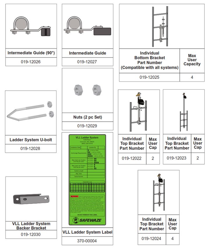
User Manual

                                                   WARNING
These instructions must be provided to any person utilizing this equipment. The worker must read and understand
the manufacturer’s instructions for this, and all other components of the complete Fall Protection System. It is
expected that all personnel be fully trained in the safe installation and use of this equipment. These instructions
must be followed for the proper use, maintenance, and inspection of this equipment. These instructions must
be kept and made available to worker’s at all times. Any alteration, misuse, or use of this equipment outside the
scope of the manufacturer’s instructions, may result in serious injury or death. A comprehensive Fall Protection
Plan must be kept on file and available to all employees at all times.
Inspect all components of this system prior to to each use and at least annually. Inspect in accordance with the
user instructions. If this equipment is exposed to the forces of a Fall Arrest or Impact Force, the equipment must
be removed from service and inspected by a Competent Person prior to being used again.
Do not connect to the Ladder Climb System while it is being installed. When unpacking the cable assembly, ensure
that proper PPE is used as cable may rapidly uncoil when released from packing. Connections of a Full Body
Harness (FBH) to the system must be made with approved connections only. The cable assembly included with this
system, is the only cable constituent authorized for use with the system.
This product is part of a complete fall protection system. User’s must utilize, and connect to the Safewaze
 Ladder Climb System with ANSI Z359 compliant restraint or Personal Fall Arrest Systems (PFAS). This product is
not designed, nor should be used as a component for a Postioning, Suspension, or Restraint. A PFAS is typically
composed of a Full Body Harness, Anchorage, and a Connecting Device. Connecting Devices used with the
SafeWaze Ladder Climb System are Energy Absorbing Lanyards (EAL’s) or a Self Retracting Device (SRD). The
connection point to the FBH for use of a SafeWaze Ladder Climb System is the Sternal (Front) D-ring.
Personnel must always maintain 3 points of contact during climbing operations. If utilizing components from
different manufacturer’s, ensure that all components are compatible and meet all applicable standards, codes, and
requirements. Before using this equipment, consult with a Competent and/or Qualified Person.
Consult your doctor if there is reason to doubt your fitness to safely absorb the shock from a fall arrest. Age
and fitness seriously affect a worker’s ability to withstand falls. Pregnant women or minors must not use this
equipment. Failure to heed this warning may result in serious injury or death.
Never exceed the maximum allowable capacity of your fall protection equipment. Never exceed the maximum free
fall distance of your fall protection equipment.
Do not use this system or any other part of a PFAS that fails pre-use or other scheduled inspections. For any
questions or concerns regarding the use of this equipment, for an application not specified in this manual, contact
SafeWaze technical support.
Additional precautions should be used when working in environments of high heat, electrical hazards, chemical
hazards, explosive or combustible chemicals, toxic materials, sharp edges, or where equipment used above could
topple onto a user below, or their fall protection equipment.
Use of a body belt for fall protection applications is not permitted. Only use an approved Full Body Harness.
Make considerations for eliminating or minimizing all swing fall hazards. Swing falls occur when the anchor is not
directly above the location where a fall occurs. Always work as close to in line with the anchor point as possible.
Swing falls significantly increase the likelihood of serious injury or death in the event of a fall.
Contact SafeWaze if you have questions, regarding compatibility of this equipment, that are not covered in this
manual. Do not alter or misuse this equipment. Some subsystem components could affect the performance and
the operation of this equipment. Do not anchor this product to moving machinery, or hazards that have chemical,
electrical or gaseous characteristics. Failure to comply with this warning could result in serious injury or death.

                                        V1.7 2021 Copyright SafeWaze                                        Page 1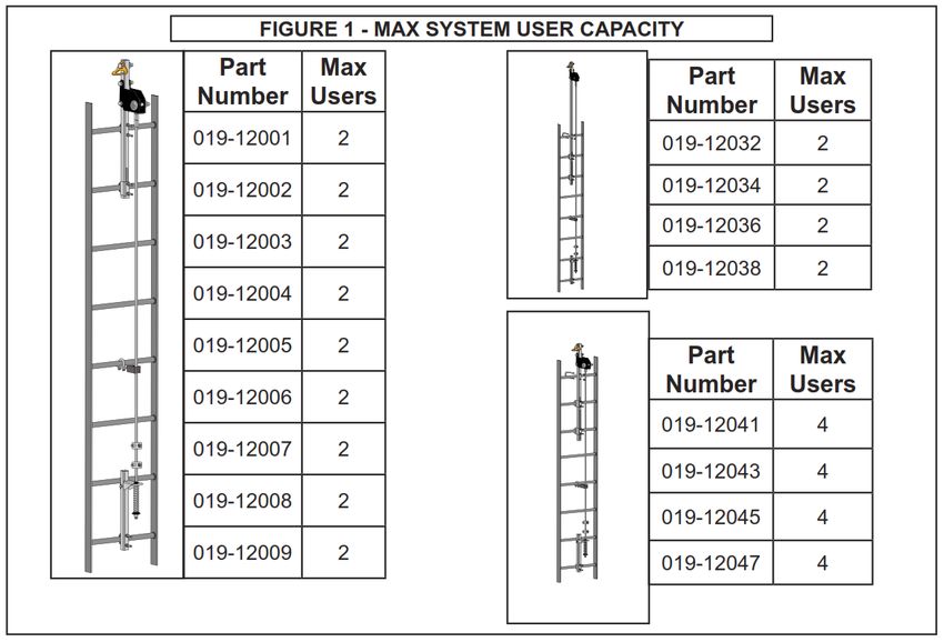
User Manual

                       Table of Contents

 1   INTRODUCTION & SCOPE OF USE................3
 2   APPLICABLE SAFETY STANDARDS............... 3
 3   WORKER CLASSIFICATIONS.......................... 3
 4   PRODUCT SPECIFIC APPLICATIONS............. 3
 5   LIMITATIONS..................................................... 4
 6   COMPATIBILITY OF CONNECTIONS.............4-5
 7   MAKING CONNECTIONS................................6-7
 8   COMPONENTS AND SPECIFICATIONS.........7-9
 9   MATERIALS....................................................... 9
10   STRUCTURE LOAD REQUIREMENTS........... 10
11   INSTALLATION...............................................11-19
12   SYSTEM USE.................................................19-22
13   INSPECTION AND MAINTENANCE ............... 23
14   LABELS............................................................ 24
15   INSPECTION LOG........................................... 25

                      V1.7 2021 Copyright SafeWaze                       Page 2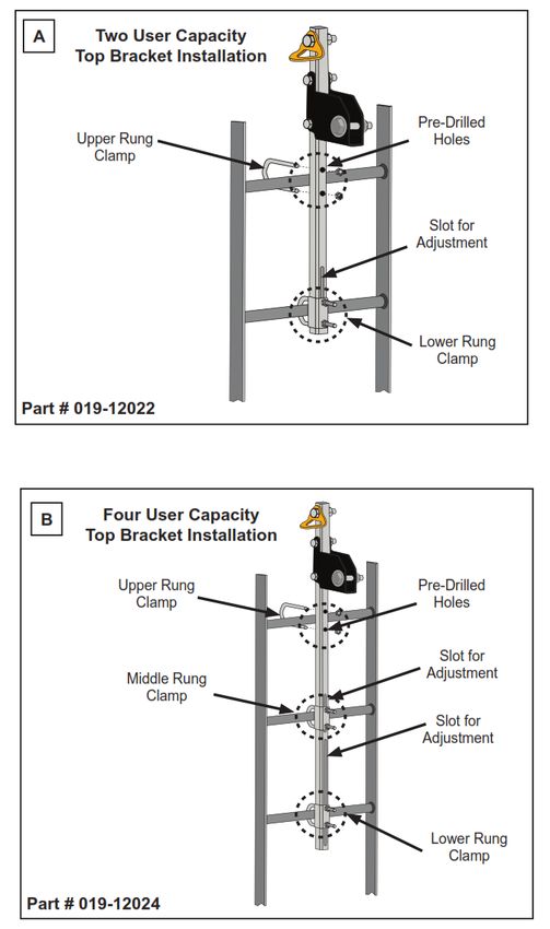
User Manual

1.0 Introduction & Scope of Use
The SafeWaze Ladder Climb System is to be used as part of a Personal Fall Protection
System (PFAS). This Ladder System is designed to protect a worker(s) in the event of
a fall while ascending or decending a fixed ladder or similar structure, with a compliant
wire rope fall arrester. The SafeWaze Ladder Climb System is intended to be installed
on fixed ladders, or ladder like assemblies that are part of a structure (i.e., antenna
and tower structures, manways, buildings, and wood, steel, or concrete mono poles).
Always wear a Full Body Harness with a Sternal (Front) D-ring attachment point that
conforms with ANSI Z359.11 or relevant national standard.

2.0 Applicable Safety Standards
                                               ANSI STANDARDS
 ANSI   Z359.0    Definitions and Nomenclature Used for Fall Protection and Fall Arrest
 ANSI   Z359.1    Safety Requirements for Personal Fall Arrest Systems, Subsystems, and Components
 ANSI   Z359.2    Minimum Requirements for a Comprehensive Managed Fall Protection Program
 ANSI   A14.3     American National Standard for Ladders - Fixed - Safety Requirements
                                              OSHA REGULATIONS
 OSHA 1910.29       Fall Protection Systems and Falling Object Protection Criteria and Parctices
 OSHA 1926.1053     Stairways and Ladders

3.0 Worker Classifications
                  Understand the definitions of those who work in proximity of or may be
                  exposed to fall hazards.

Qualified Person: A person with an accredidated degree or certification, and with
extensive experience or sufficient professional standing, who is considered proficient in
planning and reviewing the conformity of fall protection and rescue systems.

Competent Person: A highly trained and experienced person who is assigned by the
employer to be responsible for all elements of a fall safety program, including, but not
limited to, its regulation, management, and application. A person who is proficient in
identifying existing and predictable hazards, and who has the authority to stop work in
order to eliminate hazards.

Authorized Person: A person who is assigned by their employer to work around or be
subject to potential or existing fall hazards.

It is the responsibility of a Qualified or Competent person to supervise the job
site and ensure safety regulations are complied with.
4.0 Product Specific Applications
Personal Fall Arrest: The SafeWaze Ladder Climb System can be used as part of a
complete Personal Fall Arrest System (PFAS) for a maximum of 4 users
(Part# 019-12024). The structure utilized for attachment must be capable of
withstanding a load of 5,000 lbs in all directions permitted by the system.
                                      V1.7 2021 Copyright SafeWaze                                   Page 3
User Manual

5.0 Limitations
Fall Clearance: There must be sufficient clearance below the anchorage connector to
arrest a fall before the user strikes the ground or an obstruction. When calculating fall
clearance, account for a MINIMUM 2’ safety factor, deceleration distance, user height,
length of Lanyard/SRL, and all other applicable factors.
The SafeWaze Ladder Climb System is not designed, nor intended, to be installed on
portable ladders. This system is designed for use on structures that primarily vertical.
The system should never be used on a structure that exceeds a 15° degree angle from
vertical.
Full Body Harnesses
Only Full Body Harnesses with a sternal (front) D-ring may be used with the Safewaze
Ladder Climb System.
Note: Never use combinations of components or subsystems that may affect, or
interfere with the safe function of each other.
                                FIGURE 1 - MAX SYSTEM USER CAPACITY
                         Part   Max                                                   Part            Max
                        Number Users                                                 Number          Users
                        019-12001         2                                         019-12032           2

                        019-12002         2                                         019-12034           2
                                                                                    019-12036           2
                        019-12003         2
                                                                                    019-12038           2
                        019-12004         2

                        019-12005         2
                                                                                      Part            Max
                        019-12006         2
                                                                                     Number          Users
                                                                                    019-12041           4
                        019-12007         2
                                                                                    019-12043           4
                        019-12008         2
                                                                                    019-12045           4
                        019-12009         2                                         019-12047           4

**NOTE: Maximum User Ratings as indicated in these system charts require the use of an ANSI Z359.16 Cable Fall
Arreter. If a Cable Fall Arrester is used which does not meet the ANSI requirements, then all systems are limited to the
OSHA reqirements of Max. 1 user. The Number of Climbers (as defined by ANSI) for climbing Ladder Fall Arrest Systems
shall be designed for a minimum of 2 simulataneous users. This is necessary to facilitate rescue. The maximum number
of simultaneous users allowed on the system should be determined by a competent person based on the job site
conditions and any limitations set by the manufacturer.

                                         V1.7 2021 Copyright SafeWaze                                          Page 4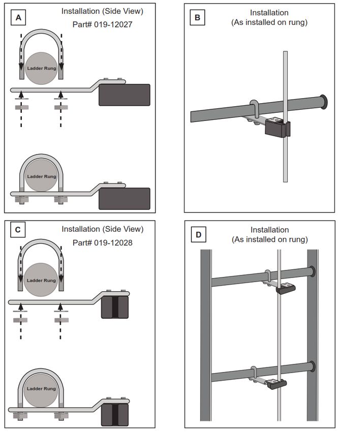
User Manual

The following limitations must be considered prior to installing the SafeWaze Ladder
Climb System:
     1. Structure: The structure to which the system is attached must be capable of
        withstanding the loads applied by the system in the event of a fall.

  2. System Capacity: The maximum number of users allowed on the SafeWaze
     Ladder Climb System simultaneously is 2, with a maximum weight of 310 lbs
     per user (including clothing, tools, and equipment). System numbers
     019-12041, 019-12043, 019-12045, and 019-12047 allow a maximum
     number of 4 users with a maximum weight of 310 lbs per user.
     Maximum number of users per system is based upon use of the EVO 3/8”
     Cable Sleeve or a comparable ANSI Z359.16 rated Cable Sleeve.

  3. Environmental Hazards: Use of the SafeWaze Ladder Climb System in
     areas where environmental hazards exist may require additional precautions.
     These hazards may consist of, but are not limited to: Electrical, Chemical,
     Thermal,Seawater, Corrosive Agents, Explosive Gasses, Toxic Gasses,
     Moving Machinery, and Sharp Edges.

6.0 Compatibility Of Connections
Connectors are compatible with connecting elements when they have been designed
to work together in such a way that their sizes and shapes do not cause their
gate mechanisms to inadvertently open regardless of how they become oriented.
Connectors (hooks, carabiners, and D-rings) must be capable of supporting at least
5,000 lbs. (22.2 kN). Connectors must be compatible with the anchorage or other
system components. Do not use equipment that is not compatible. Non-compatible
connectors may unintentionally disengage (See Figure 2). Connectors must be
compatible in size, shape, and strength. Self-locking snap hooks and carabiners are
required by ANSI Z359 and OSHA guidelines. Contact SafeWaze
if you have any questions about compatibility.

            NOTE: SOME SPECIALITY CONNECTORS HAVE ADDITIONAL REQUIREMENTS.
            CONTACT SAFEWAZE WITH QUESTIONS.

                               FIGURE 2 - UNINTENTIONAL DISENGAGEMENT

      1 - Non-compliant part                                             4 - and parts disengage.
                                                        3 - gate opens

                                     2 - gate presses
                                          against
                                      non-complaint
                                            part

                                      V1.7 2021 Copyright SafeWaze                                  Page 5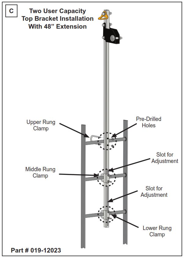
User Manual

Using a connector that is undersized or irregular in shape (1) to connect a snap hook
or carabiner could allow the connector to force open the gate of the snap hook or
carabiner. When force is applied, the gate of the hook or carabiner presses against
the non-compliant part (2) and forces open the gate (3). This allows the snap hook or
carabiner to disengage (4) from the connection point.

7.0 Making Connections
Snap Hooks and Carabiners must be ANSI Z359.12 compliant with a double locking
gate. Ensure all connections are compatible in size, shape and strength. Do not use
equipment that is not compatible. Ensure all connectors are fully closed and locked.

SafeWaze connectors (snap hooks and carabiners) are designed to be used only
as specified in each product’s user’s instructions. See Figure 3 for examples of
inappropriate connections. Do not connect snap hooks and carabiners:

• To a D-ring to which another connector is attached.
• In a manner that would result in a load on the gate (with the exception of tie back
  hooks).
• In a false engagement, where features that protrude from the snap hook or
  carabiner catch on the anchor, and without visual confirmation seems to be fully
  engaged to the anchor point.
• To each other.
• By wrapping the web lifeline around an anchor and securing to lifeline except as
  allowed for Tie Back models.
• To any object which is shaped or sized in a way that the snap hook or carabiner will
  not close and lock, or that roll-out could occur.
• In a manner that does not allow the connector to align properly while under load.

  **NOTE: Large snap hooks must not be connected to objects which will result in a load on the gate if the hook twists
  or rotates, unless the snap hook complies with ANSI Z359.1-2007 or ANSI Z359.12 and is equipped with a 3,600 lb
  (16 kN) gate. Check the marking on your snap hook to verify its compatibility.

The SafeWaze Ladder Climb System is designed for use with an ANSI Z359.16 3/8”
Wire Rope Grab. The use of any other type of grab may be incompatible with the
system, and could create a serious safety hazard for the user. Do not use the
SafeWaze Ladder Climb System without first consulting with a Competent and/or
Qualified Person at the worksite for approval. For any other questions regarding
compatibility, please contact SafeWaze Technical Support

  **NOTE: ANSI Z359.1-2007 Safety Requirements for Personal Fall Arrest Systems, Subsystems and Components,
  requires a Competent Person and/or a Qualified Person to “ensure that systems assembled from components and
  subsystems made by different manufacturers meet the requirements of the Standard.”

                                       V1.7 2021 Copyright SafeWaze                                            Page 6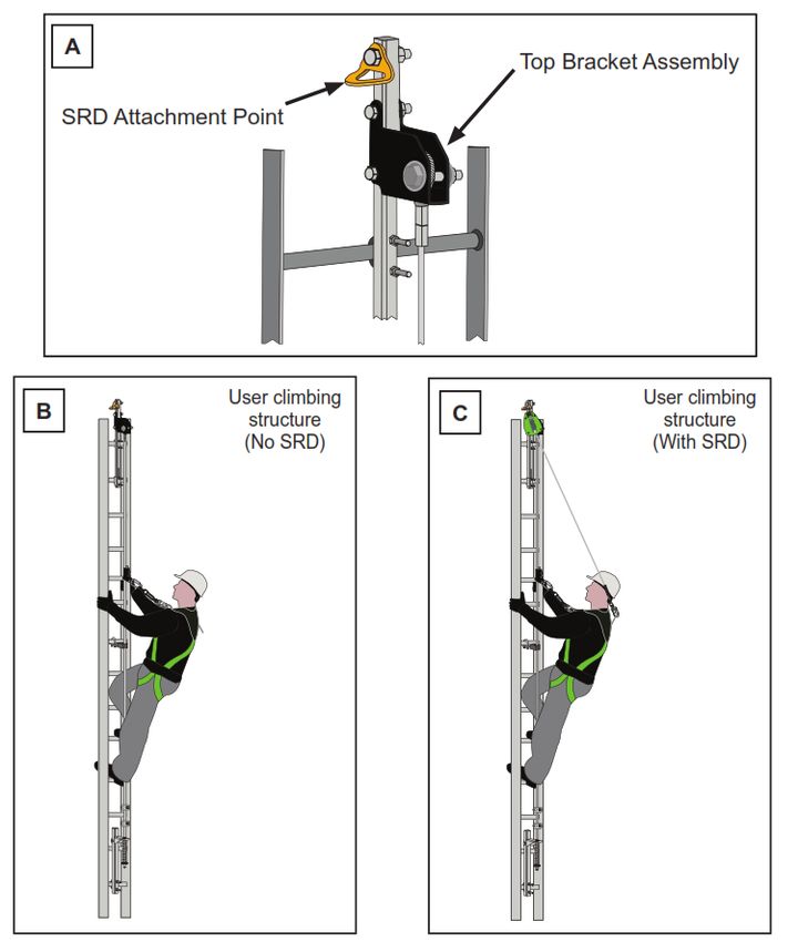
User Manual

     **NOTE: Large throat snap hooks must not be connected to standard size D-rings or similar objects which
     will result in a load on the gate if the hook or D-ring twists or rotates, unless the snap hook complies with
     ANSI Z359.1-2007 or ANSI Z359.12 and is equipped with a 3,600 lb (16 kN) gate. Check the marking on
     your snap hook to verify that it is appropriate for your application.

                          FIGURE 3 - INAPPROPRIATE CONNECTIONS

8.0 Components and Specifications
                    FIGURE 4 - LADDER CLIMB SYSTEM COMPONENTS

 A
                                                D
                                                             A                     Anchor Point
 B

                                                E            B                     Top Bracket

                                                             C           Bottom Bracket Assembly
                                                F
                                                             D             Cable Attachment Point

                                                             E                    Rung Clamps

                                                G            F                          Cable

                                                             G                  Cable Stand-Off

                                                H
                                                             H                  Cable Fist Grips

                                                              I                    Rung Clamp
 C
                                            I

                                   V1.7 2021 Copyright SafeWaze                                              Page 7
User Manual

                                         2 User Capacity
    2 User Capacity                                                             4 User Capacity
                                        (w/ 48” extension)
Complete System      System         Complete System    System              Complete System        System
  Part Number        Length           Part Number      Length                Part Number          Length
   019-12001          20 ft.           019-12032         30 ft.               019-12041            30 ft.
   019-12002          30 ft.           019-12034         50 ft.               019-12043            50 ft.
   019-12003          40 ft.           019-12036         70 ft.               019-12045            70 ft.
   019-12004          50 ft.           019-12038         90 ft.               019-12047            90 ft.
   019-12005          60 ft.

   019-12006          70 ft.

   019-12007          80 ft.

   019-12008          90 ft.

   019-12009         100 ft.

  Individual Cable
   Assembly Part
      Number
                        019-12012     20 ft.   019-12016          60 ft.   019-12020    100 ft.

                        019-12013     30 ft.   019-12017          70 ft.   019-12021    Custom

                        019-12014     40 ft.   019-12018          80 ft.

                        019-12015     50 ft.   019-12019          90 ft.

                                V1.7 2021 Copyright SafeWaze                                        Page 8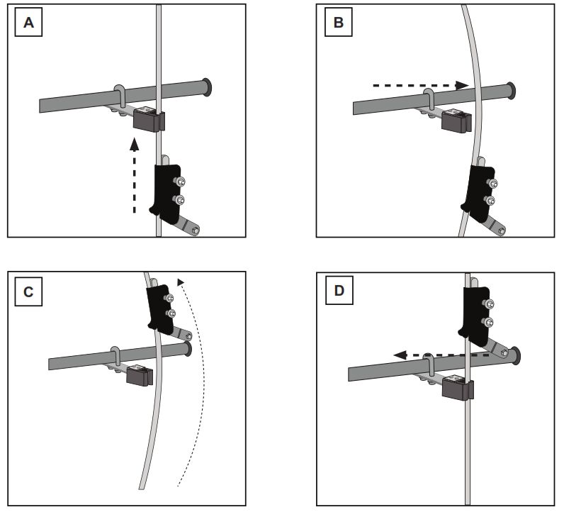
User Manual

       Intermediate Guide (90°)      Intermediate Guide                                                                   Individual
                                                                                                                                                   Max
                                                                                                                      Bottom Bracket              User
             019-12026                              019-12027                                                           Part Number              Capacity
                                                                                                                 (Compatible with all systems)

                                                                                                                          019-12025                  4

                                              Nuts (2 pc Set)

                                                    019-12029

        Ladder System U-bolt
                                                 VLL Ladder System
                                                              SafeWaze                                            Individual Max          Individual Max
                                                                                                                 Top Bracket User        Top Bracket User
                                                          Concord, NC 28025
                                                            (800) 230-0319

             019-12028                Installation Date                      Installed By

                                                                              = 2,700 lbs (12kN)
                                                                                                                 Part Number Cap         Part Number Cap
                                                                                 = 3,320 lbs (14.8kN)
                                       Anchorage Requirements
                                                                                    = 3,940 lbs (17.5kN)

                                                                                                                                         019-12023       2
                                                                                      = 4,560 lbs (20.3kN)

                                          Max Users per System
                                                                          019-12022 =
                                                                          019-12023 =
                                                                                                                 019-12022       2
                                            (310 lbs per user)
                                                                          019-12024 =
                                                                          019-12022 =
                                          Max Users per System
                                                                          019-12023 =
                                            (420 lbs per user)
                                                                          019-12024 =

                                               System Length

                                                 Mfg. Date

                                               Serial Number

                                                                Inspection Log
                                              JAN FEB MAR APR MAY JUN JUL AUG SEP OCT NOV DEC

                                                          Failure to heed warnings related to this system may
                                      result in serious injury or death. Manufacturer’s instructions supplied
                                      with this product at time of shipment must be followed for proper
                                      installation, use, inspection, and maintenance of this equipment.
                                      Unauthorized alteration or substitution of components for this system is
                                      prohibited. Use only with compatible personnel equipment authorized
                                      per manufacturer’s instructions. System must be inspected prior to
                                      each use, and at least annually by a competent person other than the
                                      user. Annual inpsections should be documented in the inpsection grid
                                      on this label, as well as the instruction manual. The climbing structure
                                      to which this system is attached must also be inspected, in accordance
                                      with its individual inspection criteria. Minimum spacing between user’s
                                      of this system is 20 ft.

                                                     DO NOT REMOVE THIS LABEL

                                                                                                                           Individual Max
         VLL Ladder System           019768
                                                                                                                          Top Bracket User
           Backer Bracket                                                                                                 Part Number Cap
                                  VLL Ladder System Label
             019-12030
                                                                                                                             019-12024     4
                                                    370-00004

9.0 Materials
Top and Bottom Bracket: Galvanized Steel and Stainless Steel
Cable Assembly: 3/8” 7x19 Galvanized Cable
Tensioner: Galvanized Steel Body, Stainless Steel Spring
Fist Grips: Drop Forged Steel, Hot Dipped Galvanized
Cable Stand-Off’s: Galvanized Steel Harware, Synthetic Rubber Guide
SRD Attachment Point: Forged Steel (Painted)
                                    V1.7 2021 Copyright SafeWaze                                                                                             Page 9
User Manual
10.0 Structure Load Requirements
The structure to which the Ladder Climb System is attached must be capable of
withstanding the total loads imposed by the system.
9.1 Static Loading: The static loads imposed on the system include the weight
of the top bracket, weight of the length of cable used with the system and a
Safety Factor. The following is an example of static loads imposed on the
system for a 50 ft (15.24 m) system:
Top Bracket Weight = 24 lbs (10.9 kg)
50 ft. (15.24 m) of 3/8” (9.5 mm) Galvanized Cable Weight = 13.25 lbs (6.01 kg)
Total Static Loading: (24 lbs + 13.25 lbs) x 1.2 (Safety Factor) = 47.3 lbs
9.2 Dynamic Loading: The following are the Dynamic Loads imposed onto the
Ladder Climb System per user:
One User = 2,700 lbs (12 kN)
Two Users = 3,320 lbs (14.76 kN)
Three Users = 3,940 lbs (17.51 kN)
Four Users = 4,560 lbs (20.27 kN)
9.3 Total Loading: The total load must account for the Static and Dynamic
Loading indicated above for the total length of the sytem. The following is
an example of the Total Loading imposed onto the structure given that the
example system is 50 ft (15.24 m) in length:
Static Loading for a 50 ft. (15.24 m) system = 47.3 lbs
Dynamic Load for Two Users = 3,320 lbs
Total Loading = 47.3 lbs + 3,320 lbs = 3,367.3 lbs
Bottom Bracket Assembly: The bottom bracket assembly connection point
must be capable of supporting the system pretension load of 350 lbs (1.6 kN)
in the direction of loading. The required bracket load may be assumed to be
distributed evenly between the number of rung attachments for calculation
purposes.
Total Loading of the system onto the attachment structure can be reduced by limiting
the number of user’s on the system.
V1.7 2021 Copyright SafeWaze Page 10User Manual
11.0 Installation
Installation of the SafeWaze Ladder Climb System must be supervised by a Qualified
Person.
Before Each Use
Users of personal fall arrest systems must have a rescue plan in place, if the user
cannot rescue themselves, as well as the means to carry out the rescue.
The user must read and understand these User Instructions, as well as the User
Instructions for every component/subsystem of the personal fall arrest system.
The entire Safewaze Ladder Climb System, and its subsystems, must be inspected
prior to each use for wear, damage, and other deterioration. All snaphooks and
carabiners must be able to self-close and lock. System must be properly tensioned.
No load indicators shall be deployed (See Figure 13, page 20). Damaged and other
deteriorated and defective components must be immediately removed from service,
in accordance with the requirements of OSHA 29 CFR 1910.66 and 1926.502.
In order to begin installation of the SafeWaze Ladder Climb System the installer needs
to know the part numbers of the system, the number of Stand-Off’s required, and
length of the cable assembly. Inspect all components of the system prior to beginning
installation to ensure no damge occurred during shipping. In the event any damage is
discovered during the pre-installation inspection, contact SafeWaze for replacement
guidance.
The SafeWaze Ladder Climb System is designed for easy installation onto a variety of
suitable structures. For systems 50 ft. or greater in length, a cable stand-off must be
used. A cable stand-off must be used every 25 ft to 30 ft on systems greater than
50 ft in length.
As a general rule, the SafeWaze Ladder Climb System should be installed from the top
of the structure down.
Installation Steps:
Step 1: Install the Top Bracket onto the top two rungs of the ladder.
Step 2: Connect the cable to the Top Bracket
Step 3: Install the Cable Stand-Off’s as necessary
Step 4: Install the Bottom Bracket Assembly
Step 5: Tension the Cable
Step 6: Inspect the Installation
Installation time can be reduced, and safety increased, by pre-planning the installation
process.
V1.7 2021 Copyright SafeWaze Page 11User Manual
Step 1: Installation of Top Bracket
Prior to installation of the Top Bracket, a Qualified Person should determine that the
structure is capable of meeting the load requirements of the system. Ensure that the
Top Bracket is positioned to allow users safe access when connecting or disconnecting
from the system. As a general rule, the Top Bracket is centered on the climbing
structure to allow for ease of climbing. However, the bracket may be installed
towards the side of the structure if necessary (See Section 10).
Two User Capacity Top Bracket - Part# 019-12022 (Figure 5A): Line up the
pre-drilled holes on the bracket with the top rung of the climbing structure. Slide the
upper rung clamp over the back of the rung and through the two pre-drilled holes in the
bracket. Thread nuts onto the rung clamps and torque to 20-25 ft. lbs. The Top Bracket
includes a pre-cut slot for adjustment to align the lower rung clamp with the lower rung.
Position the lower rung clamp on the lower rung using the pre-cut slot, install the nuts
onto the clamp, and torque to 20-25 ft. lbs.
Two User Capacity Top Bracket with 48” Extension - Part# 019-12023 (Figure 5C):
Line up the pre-drilled holes on the bracket with the top rung of the climbing structure.
Slide the upper rung clamp over the back of the rung and through the two pre-drilled
holes in the bracket. Thread nuts onto the rung clamps and torque to 20-25 ft. lbs. The
Top Bracket includes pre-cut slots for adjustment to align the middle and lower rung
clamps with their corresponding rungs. Position the middle and lower rung clamps on
the rungs,install the nuts onto the clamps, and torque to 20-25 ft. lbs.
Four User Capacity Top Bracket - Part# 019-12024 (Figure 5B): Line up the
pre-drilled holes on the bracket with the top rung of the climbing structure. Slide the
upper rung clamp over the back of the rung and through the two pre-drilled holes in the
bracket. Thread nuts onto the rung clamps and torque to 20-25 ft. lbs. The Top
Bracket includes pre-cut slots for adjustment to align the middle and lower rung clamps
with their corresponding rungs. Position the middle and lower rung clamps on the
rungs,install the nuts onto the clamps, and torque to 20-25 ft. lbs.
V1.7 2021 Copyright SafeWaze Page 12User Manual
FIGURE 5 - TOP BRACKET INSTALLATION
A Two User Capacity
Top Bracket Installation
Pre-Drilled
Upper Rung Holes
Clamp
Slot for
Adjustment
Lower Rung
Clamp
Part # 019-12022
B Four User Capacity
Top Bracket Installation
Upper Rung Pre-Drilled
Clamp Holes
Slot for
Middle Rung Adjustment
Clamp
Slot for
Adjustment
Lower Rung
Clamp
Part # 019-12024
V1.7 2021 Copyright SafeWaze Page 13User Manual
C Two User Capacity
Top Bracket Installation
With 48” Extension
Pre-Drilled
Upper Rung
Holes
Clamp
Slot for
Adjustment
Middle Rung
Clamp
Slot for
Adjustment
Lower Rung
Clamp
Part # 019-12023
Rung Spacing and Diameter Compatibility:
Spacing 9” - 12.25” (200mm - 310mm)
Cylindrical Rung 0.5” - 1.6” (13mm-40mm) diameter
Square Rung 0.5” - 1.6” (13mm-40mm) diameter
Diamond Rung 0.5” - 1.6” (13mm-40mm) height
Angle Iron 0.5” - 1.6” (13mm-40mm) leg height
Rectangular Rung 0.5” - 1.6” (13mm-40mm) height, 0.5” - 1.9” (13mm-48mm) width
V1.7 2021 Copyright SafeWaze Page 14User Manual
Step 2: Connect the Cable to the Top Bracket
Prior to connecting the Cable Asembly to the Top Bracket, take the cable and uncoil it
on ground in a clean area and inspect for any damage. If any shipping damage is found
on the Cable Assembly, DO NOT USE.
To connect the cable to the Ladder Climb System, first remove the Cable Connection
Bolt from the Top Bracket Assembly (See Figure 6A). Insert the thimble end of
the cable through the pre-cut slot in the bottom of the Top Bracket Assembly
(See Figure 6A). Align the thimble end of the Cable Assembly within the Top Bracket
and re-insert the Cable Connection Bolt through the Top Bracket and the thimble end
of cable. Thread nut onto the Cable Connection Bolt and tighten to 40 to 45 ft-lbs
(See Figure 6B & 6C).
FIGURE 6 - CONNECT CABLE TO TOP BRACKET
A B C
Step 3: Install Cable Stand-Off’s
The Ladder Climb System Cable Stand-Off’s are designed to prevent abrasion of the
Cable Assembly on ladder rungs and to prevent excessive movement of the cable from
side to side while the user is climbing. They can also be used if high winds are
prevalent at the structure location to reduce harmonic vibration on the cable assembly.
The Stand-Off’s should be installed every 25-30 ft. along the cable between the Top
and Bottom Brackets. See Figure 7A & 7B for typical installation. In instances where
high winds may be prevalent, Stand-Off’s that are oriented in an “L” shape can be
installed. The “L” type Stand-Off’s should be installed in a interval orientation to the
cable (left and right) as the example indicates in Figures 7C & 7D.
V1.7 2021 Copyright SafeWaze Page 15User Manual
FIGURE 7 - INSTALL CABLE STAND-OFF’S
Installation (Side View) Installation
A B
Part# 019-12027 (As installed on rung)
Ladder Rung
Ladder Rung
C Installation (Side View) Installation
D
Part# 019-12028 (As installed on rung)
Ladder Rung
Ladder Rung
V1.7 2021 Copyright SafeWaze Page 16User Manual
Step 4: Install Bottom Bracket Assembly
Align pre-drilled holes on the bracket with the bottom rung of the climbing structure.
Slide the rung clamp over the back of the rung and through the two pre-drilled holes in
the bracket (See Figure 8). Thread nuts onto the rung clamp. Tighten the rung clamp to
20-25 ft-lbs.
FIGURE 8 - BOTTOM BRACKET INSTALLATION
Tensioner
Rod
Rung Clamp
Step 5: Tension the Cable
Loosen the cable fist grips to attach the cable assembly to the tensioner rod on the
Bottom Bracket assembly. Insert cable through fist grips, remove excess slack from
the system by hand, but do not yet fully re-tighten fist grips (See Figure 9A & 9B).
FIGURE 9 - ATTACH CABLE TO TENSIONER ASSEMBLY
A Fist Grip B Fist Grip
Cable Tensioner
Rod
Fist Grip
V1.7 2021 Copyright SafeWaze Page 17User Manual
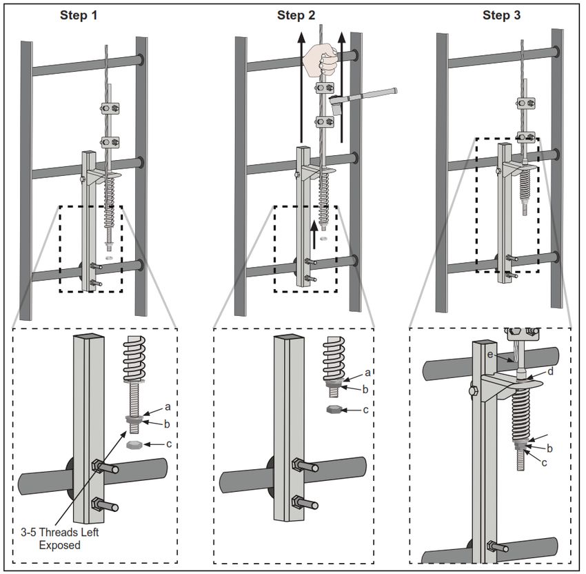
Slide washer (a) onto tensioning assembly. Thread the tensioning nut (b) onto
tensioner until approximately 3 to 5 threads are exposed below the nut (See Figure 10
- Step 1). Pull up on Tension Assembly until washer (a) contacts bottom of spring.
Ensure excess cable slack is again removed from system and torque fist grips to
35 ft-lbs. (See Figure 10 - Step 2). Tighten tensioning nut (b) on tensioner until 1/2” of
tension indicator (d) is visible or cable is taut. Tighten locking nut (c) until snug to
tensioning nut (b). Cut excess slack off end of cable (e) (See Figure 10 - Step 3).
FIGURE 10 - TENSION THE CABLE
Step 1 Step 2 Step 3
e
a d
b
a c
b
c b
c
3-5 Threads Left
Exposed
V1.7 2021 Copyright SafeWaze Page 18User Manual
Step 6: Inspect the Installation
Affix the installation and inspection label in a prominent location on the structure (See
Section 14 for example Labels).
Before installing the label mark the following:
- Installation Date
- Installer
- Maximum Number of Users per system
- System Length
After installation, the installer must inspect the system as follows:
- Ensure all fasteners are torqued to proper levels as per instructions
- Verify proper tension of the cable assembly and connection to bottom bracket
- Ensure all cable assembly components are installed as per instructions
- Visually inspect the cable assembly to confirm it does not abrade at any point
on climbing structure
- Confirm that the system information is recorded on the label
12.0 System Use
After installation, labeling, and inpsection of the system as defined in Section 12.0, the
SafeWaze Ladder Climb System is ready for use.
User’s of this system must be trained in it’s use, and must read and understand all
instructions provided with the system at time of shipment.
PPE must be utilized by all user’s. This should include, but is not limited to, eye
protection, hard hat, appropriate footwear, gloves, and any other equipment deemed
necessary by the Competent Person onsite.
A Full Body Harness (FBH) equipped with a Sternal (Front) D-ring, is required for use
of this system.
A 3/8” wire-rope grab is required in order to safely uitize the system.
Attach the 3/8” wire-rope grab to the cable assembly prior to beginning any climing of
the structure.
Once attached to the cable assembly, the user can begin climbing the structure. The
user should always ensure that the wire-rope grab is as high as possible on the cable
assembly, relative to their body position.
V1.7 2021 Copyright SafeWaze Page 19User Manual
SRD Use with the Ladder Climb System System: The SafeWaze Ladder Climb
System is equipped with an anchorage point on the Top Bracket Assembly for
connection (See Figure 11A).An ANSI rated SRD can be left in place on the system if
desired. If left in place once attached to the system, use of a tag line is recommended
to prevent unnecessary wear on the main spring assembly of the SRD.
FIGURE 11 - SRD ATTACHMENT POINT
A
Top Bracket Assembly
SRD Attachment Point
User climbing User climbing
B structure C 322
Industrial
P: (704)
262-7893
SELF ING
RETRACT
LANYARD
NC
28025
Concord, 262-9051
Court,or F: (704)
A10.32
& ANSI 1926.502
structure
(No SRD) (With SRD)
Z359.14 & OSHA
ANSI ZE.COM
1910.66
OSHA
WWW.SAFEWA
**NOTE: A Qualified Person needs to determine if an SRL anchored to the top of the system is
suitable for use, as the anchor point is rated at 3,600 lbs. rather than 5,000 lbs.
V1.7 2021 Copyright SafeWaze Page 20User Manual
Operation of Cable Grab around Stand-Off’s: If the system is of sufficient length to
have required the installation of Cable Stand-Off’s, the user must manually manipulate
the Cable Assembly in order to “pass” the Stand-Off (See Figure 12A).This is
accomplished by the user pulling out slightly on the cable assembly (See Figure 12B).
This will temporarily disengage the cable from the from the Stand-Off which allows the
wire-rope grab to “pass” by the Stand-Off (See Figure 12C). Once the wire-rope grab
has passed the Stand-Off, the user must push slightly on the cable to ensure that it is
once again held in place by the Stand-Off (See Figure 12D). DO NOT attempt to
disconnect the wire-rope grab from the Cable Assembly at any time during climbing
operations. Disconnection of the wire-rope grab from the Cable Assembly during
climbing can result in serious injury or death.
FIGURE 12 - PASSING CABLE STAND-OFF’S
A B
C D
V1.7 2021 Copyright SafeWaze Page 21User Manual
Energy Absorption/Fall Indicator: The Safewaze Ladder Climb System Top Bracket
Assembly is designed to absorb fall arrest forces should a fall on the system occur. The
Top Bracket Assembly has laser cut slots on each side of the assembly, at the cable
connection point (See Figure 13A). In the event of a fall, the slots allow the metal to
deform inward and downward to absorb fall arrest forces (See Figure 13B). This
deformation of the metal indicates that the system has been exposed to fall arrest
forces. It this deformation is present during inspection, DO NOT use the system, and
REMOVE FROM SERVICE.
FIGURE 13 - ENERGY ABSORPTION / FALL INDICATOR
Top Bracket Top Bracket
A (Side View) B (Front View)
No Fall Fall Event
WARNING:
Remove from service if
tab is bent below the
Fall Indicator Line
Laser Cut
Slots Metal Bends
Inward and
Downward
Top Bracket
(Side View)
After Fall
WARNING:
Remove from service if
tab is bent below the
Fall Indicator Line
Indicates
Exposure to
Fall Arrest
Forces
V1.7 2021 Copyright SafeWaze Page 22User Manual
13.0 Inspection and Maintenance
Inspection
Inspect the device and components for corrosion and/or damage.
Check all harware for signs of damge or distortion.
Inspect cable for cuts, corrosion, heat/welding damage, birdcaging or other defects.
Ensure proper torque of all fasteners.
Frequency
All components of the SafeWaze Ladder Climb System must be inspected prior to each
use, and annually by a “competent person” (other than the user), as defined by OSHA.
Criteria
If inspection reveals any defect, inadequate maintenance, or unsafe condition, remove
from service until a “qualified person” as defined by OSHA 1926.32(m) can determine
the need for authorized repair or disposal.
Maintenance
Any SafeWaze Ladder Climb System components requiring maintenance must be
tagged “unusable” and removed from service.
Cleaning maintenance may be performed by the user.
If the cable assembly becomes heavily soiled with dirt, oil, grease, paint, etc..., it may
be cleaned with warm soapy water. Dry the assembly with a clean dry cloth after
cleaning. Do not use forced air heat to dry. Do not use corrosive or caustic chemicals
that could damage the cable assembly.
Repairs to the product may only be made by the manufacturer or entities authorized in
writing by the manufacturer.
THIS SYSTEM MUST ONLY BE SERVICED BY A TRAINED AND COMPETENT INDIVIDUAL!
NEVER ATTEMPT TO SERVICE THIS UNIT OR TAMPER WITH ITS FUNCTION IN ANY WAY!
Storage
When not installed, the SafeWaze Ladder Climb System should be stored in a cool, dry
place out of direct sunlight. Do not store in areas where damage from environmental
factors such as heat, light, excessive moisture, oil, chemicals and their vapors, or other
degrading elements may be present. Do not store damaged equipment or equipment
in need of maintenance in the same area as product approved for use. Equipment that
has been stored for an extended period must be inspected as described in these User
Instructions prior to use.
V1.7 2021 Copyright SafeWaze Page 23User Manual
14.0 Labels
Saf
01
976
9
eW
az
e
i
OSHA 192
x: 1
Ma
6.5
02 0
,O
SHA 1910.14
Ladder Climb System
SafeWaze
Concord, NC 28025
(800) 230-0319
Installation Date Installed By
= 2,700 lbs (12kN)
= 3,320 lbs (14.8kN)
Anchorage Requirements
= 3,940 lbs (17.5kN)
= 4,560 lbs (20.3kN)
019-12022 =
Max Users per System
019-12023 =
(310 lbs per user)
019-12024 =
019-12022 =
Max Users per System
019-12023 =
(420 lbs per user)
019-12024 =
System Length
Mfg. Date
Serial Number
Inspection Log
JAN FEB MAR APR MAY JUN JUL AUG SEP OCT NOV DEC
Failure to heed warnings related to this system may
result in serious injury or death. Manufacturer’s instructions supplied
with this product at time of shipment must be followed for proper
installation, use, inspection, and maintenance of this equipment.
Unauthorized alteration or substitution of components for this system is
prohibited. Use only with compatible personnel equipment authorized
per manufacturer’s instructions. System must be inspected prior to
each use, and at least annually by a competent person other than the
user. Annual inpsections should be documented in the inpsection grid
on this label, as well as the instruction manual. The climbing structure
to which this system is attached must also be inspected, in accordance
with its individual inspection criteria. Minimum spacing between user’s
of this system is 20 ft.
DO NOT REMOVE THIS LABEL
019768
V1.7 2021 Copyright SafeWaze Page 24User Manual
15.0 Inspection Log
DATE CONDITION OF SYSTEM INSPECTED
BY:
V1.7 2021 Copyright SafeWaze Page 25User Manual
WARRANTY
SafeWaze
225 Wilshire Ave SW
Concord, NC 28025
PHONE: 1-800-230-0319
FAX: 1-704-262-9051
EMAIL: info@safewaze.com
Web: safewaze.com
V1.7 2021 Copyright SafeWazeManual del usuario
SISTEMA DE SUBIDA POR ESCALERA
INSTRUCCIONES DEL USUARIO
Cumple con las normas OSHA CFR 29 1910.66, OSHA 1926.502
ANSI Z359.1 y ANSI A14.3
V1.7 2021 Copyright SafeWaze 220-00023Manual del usuario
ADVERTENCIA
Toda persona que use este equipo debe tener acceso a una copia de estas instrucciones. El usuario debe leer y
entender las instrucciones del fabricante para este y para todos los componentes de este sistema integral de protección
contra caídas. El usuario debe seguir estas instrucciones para usar, inspeccionar y mantener correctamente el equipo.
Estas instrucciones deben estar siempre a disposición del usuario. Alterar este equipo o usarlo de manera incorrecta o no
conforme a las instrucciones del fabricante puede causar lesiones graves o muerte. Debe haber siempre un plan integral
de protección contra caídas en los archivos de la empresa y a disposición de todos los usuarios.
Inspeccione todos los componentes de este sistema cada vez que lo vaya a usar y al menos una vez al año. Inspeccione
de acuerdo con las instrucciones del usuario. Si es expuesto a fuerzas de parada de caídas o a una fuerza de impacto,
este equipo debe ser puesto fuera de servicio e inspeccionado por una persona competente antes de volver a usarlo.
No se conecte al sistema de subida por escalera mientras lo esté instalando. Póngase equipo de protección personal
adecuado antes de desempaquetar la unidad de cable, ya que el cable puede desenrollarse rápidamente al soltar las
amarras del paquete. Los Arneses de Cuerpo Entero (Full Body Harness, FBH) se deben conectar al sistema solo con
dispositivos de conexión aprobados. La unidad de cable que viene con este sistema es el único componente autorizado
para el sistema.
Los usuarios deben conectarse al sistema de subida por escalera de SafeWaze con un dispositivo restrictivo conforme a
la norma ANSI Z359 o un Sistema Personal de Parada de Caídas (Personal Fall Arrest System, PFAS). Este producto no
ha sido diseñado ni se debe usar como componente de sistema de posicionamiento, suspensión o rescate. Los PFAS se
componen generalmente de un Arnés de Cuerpo Entero (Full Body Harness, FBH), un anclaje, y un dispositivo de
conexión. Los dispositivos de conexión al sistema de subida por escalera de SafeWaze son Cordones Absorbentes de
Energía (Energy Absorbing Lanyards, EAL) o Dispositivos Autorretráctiles (Self Retracting Devices, SRD). El FBH se
conecta al sistema de subida por escalera de SafeWaze por el anillo pectoral (delantero) en D.
El personal debe mantener siempre 3 puntos de contacto durante las operaciones de subida. Si utiliza componentes de
diferentes fabricantes, todos los componentes deben ser compatibles y cumplir con todos los estándares, códigos y
requisitos aplicables. Antes de usar este equipo, consulte a una persona competente y/o calificada.
Consulte al médico si duda de que su estado físico le permita absorber con seguridad el impacto de una parada de caída.
La edad y el estado físico afectan seriamente la capacidad de soportar caídas. Ni los menores de edad ni las mujeres
embarazadas deben usar este equipo. No respetar esta advertencia puede causar lesiones graves o muerte.
Nunca exceda la capacidad máxima permitida de su equipo de protección contra caídas. Nunca exceda la altura máxima
de caída libre de su equipo de protección contra caídas.
No use este sistema ni ningún componente de un PFAS que no pase la inspección que se le haga justo antes de usarlo o
de otras inspecciones previstas. Si tiene preguntas o dudas relacionadas con el uso de este equipo para alguna
aplicación no especificada en este manual, comuníquese con el apoyo técnico de SafeWaze.
Se deben tomar precauciones adicionales cuando se trabaja en lugares donde haya altas temperaturas, peligros
eléctricos, peligros químicos, productos químicos explosivos o combustibles, materiales tóxicos, bordes afilados o equipo
en alto que podría caerle encima al usuario o a su equipo de protección contra caídas.
Se prohíbe usar solo un cinturón como protección contra caídas. Use únicamente un arnés de cuerpo entero aprobado.
Elimine o minimice los riesgos de caídas pendulares, que se producen cuando el punto de anclaje no está directamente
encima del punto de caída. Trabaje siempre lo más cerca posible del punto de anclaje. Las caídas pendulares aumentan
significativamente la probabilidad de lesiones graves o muerte.
Comuníquese con SafeWaze si tiene preguntas sobre compatibilidades del equipo no consideradas en este manual.
No altere ni use incorrectamente este equipo. Algunos componentes de subsistema pueden afectar el rendimiento y el
funcionamiento de este equipo. No ancle este producto a maquinaria en movimiento ni a estructuras que impliquen
peligros químicos, eléctricos o gaseosos. No respetar esta advertencia puede causar lesiones graves o muerte.
V1.7 2021 Copyright SafeWaze Pág. 1Manual del usuario
ÍNDICE DE MATERIAS
1. INTRODUCCIÓN Y USOS .............................................................. 3
2. NORMAS DE SEGURIDAD APLICABLES ...................................... 3
3. DENOMINACIONES DE USUARIOS ............................................. .3
4. CONFIGURACIONES ESPECÍFICAS DEL PRODUCTO................ 3
5. LIMITACIONES ............................................................................... 4
6. COMPATIBILIDAD DE CONECTORES .......................................... 5
7. FORMACIÓN DE CONEXIONES ................................................ 6-7
8. COMPONENTES Y ESPECIFICACIONES ................................. 7-9
9. MATERIALES ............................................................................... 10
10. REQUISITOS DE CARGA DE LA ESTRUCTURA ........................ 10
11. INSTALACIÓN .........................................................................11-19
12. USO DEL SISTEMA .................................................................19-22
13. INSPECCIÓN Y MANTENIMIENTO .............................................. 23
14. ETIQUETAS .................................................................................. 24
15. REGISTRO DE INSPECCIONES .................................................. 25
V1.7 2021 Copyright SafeWaze Pág. 2Manual del usuario
1.0 Introducción y usos
El sistema de subida por escalera de SafeWaze se debe usar como parte de un Sistema Personal de Parada
de Caídas (Personal Fall Arrest System, PFAS). Este sistema de escalera ha sido diseñado para proteger a
los trabajadores en caso de una caída mientras suben o bajan por una escalera fija o una estructura similar
con un dispositivo de parada de caída de cable que satisface los requisitos correspondientes. El sistema de
subida por escalera de SafeWaze ha sido diseñado para ser instalado en escaleras fijas o aparatos similares
a escaleras que forman parte de una estructura (es decir, antenas, torres, edificios, pozos de inspección y
postes de madera, acero o concreto). Use siempre un arnés de cuerpo entero con un punto de conexión de
anillo en D pectoral (delantero) que cumpla con la norma ANSI Z359.11 o la norma nacional pertinente.
2.0 Normas y reglamentos de seguridad aplicables
NORMAS DEL ANSI
ANSI Z359.0 Definiciones y nomenclatura de parada de caídas y protección contra caídas
ANSI Z359.1 Requisitos de seguridad de sistemas personales de parada de caídas y sus subsistemas y componentes
ANSI Z359.2 Requisitos mínimos de programas integrales administrados de protección contra caídas
ANSI A14-3 Requisitos de seguridad de los Estándares Nacionales Estadounidenses de escaleras fijas
REGLAMENTOS DE LA OSHA
OSHA 1910.29 Criterios y prácticas de sistemas de protección contra caídas y protección contra la caída de objetos
OSHA 1926.1053 Escaleras y escalas
3.0 Denominaciones de usuarios
Entienda las denominaciones de las personas que se exponen a caídas o
trabajan cerca de estructuras que implican riesgo de caída.
Persona calificada: Persona con certificación o título homologado y amplia experiencia o suficiente prestigio
profesional que se considera competente en la planificación y revisión de la conformidad de los sistemas de
rescate y protección contra caídas.
Persona competente: Persona altamente capacitada y experimentada que el empleador responsabiliza de
todos los elementos de un programa de seguridad contra caídas, tales como, entre otros, regulación,
administración y aplicación. Esta persona es competente en cuanto a la identificación de peligros conocidos y
predecibles, y está autorizada a suspender el trabajo para eliminar los peligros.
Persona autorizada: Persona nombrada por el empleador para exponerse a riesgos de caídas conocidos o
posibles, o trabajar cerca de lugares en que existen tales riesgos.
Las personas calificadas o competentes son responsables de supervisar el lugar de trabajo y
garantizar que se cumplan las normas de seguridad.
4.0 Configuraciones específicas del producto
Parada de caída personal: El sistema de subida por escalera de SafeWaze forma parte de un Sistema
Personal de Parada de Caídas (Personal Fall Arrest System, PFAS) para un máximo de 4 usuarios (Pieza
Nro. 019-12024). La estructura a la cual se fija debe soportar una carga de 5,000 libras en todas las
direcciones permitidas por el sistema.
V1.7 2021 Copyright SafeWaze Pág. 3Manual del usuario
5.0 Limitaciones
Altura de caída: Debe haber suficiente espacio debajo del conector de anclaje para parar una caída antes de
que el usuario llegue al suelo o se golpee contra algo. Cuando calcule la altura de caída, considere la
distancia de desaceleración, la estatura del usuario, la longitud del cordón o la SRL, un factor de seguridad de
2 pies como MÍNIMO, y todo otro factor aplicable.
El sistema de subida por escalera de SafeWaze no es para escaleras portátiles. Este sistema es para
estructuras esencialmente verticales. El sistema nunca debe usarse en estructuras con más de 15° de
inclinación.
Arneses de cuerpo entero
Se deben usar solo arneses de cuerpo entero con anillo pectoral (delantero) en D con el sistema de subida
por escalera de SafeWaze
Nota: Nunca use combinaciones de componentes o subsistemas que puedan afectar su funcionamiento
correcto o interferirse mutuamente.
FIGURA 1 - CAPACIDAD MÁXIMA DE USUARIOS DEL SISTEMA
Número de Máx. de
Número de Máx. de
pieza usuarios
pieza usuarios
Número de Máx. de
pieza usuarios
**NOTA: Las capacidades máximas de usuarios indicadas en estos cuadros del sistema requieren un dispositivo de parada de caída
de cable conforme a la norma ANSI Z359.16. Si el dispositivo de parada de caída no cumple con los requisitos del ANSI, todos los
sistemas quedan limitados a los requisitos de la OSHA para una capacidad máxima de 1 usuario. Basándose en la definición de
usuario del ANSI, los sistemas de subida por escalera se deben diseñar para un mínimo de 2 usuarios simultáneos. Esto es necesario
para facilitar el rescate. El número máximo de usuarios simultáneos permitidos en el sistema debe ser determinado por una persona
competente en función de las condiciones del lugar de trabajo y las limitaciones establecidas por el fabricante.
V1.7 2021 Copyright SafeWaze Pág. 4Manual del usuario
Se deben considerar las siguientes limitaciones antes de instalar el sistema de subida por escalera de
SafeWaze:
1. Estructura: La estructura a la cual se fija el sistema debe ser capaz de soportar las cargas aplicadas
por el sistema en caso de caída.
2. Capacidad: El número máximo de usuarios que pueden encontrarse simultáneamente en el sistema
de subida por escalera de SafeWaze es de 2 personas, con un peso máximo de 310 libras por usuario
(incluida la ropa, las herramientas y el equipo). Los sistemas número 019-12041, 019-12043, 019-
12045 y 019-12047 permiten un máximo de 4 usuarios con un peso máximo de 310 libras por usuario.
El número máximo de usuarios por sistema se basa en el uso de la manga de cable EVO de 3/8 de
plg. o una manga de cable similar que cumpla con la norma ANSI Z359.16.
3. Peligros ambientales: El uso de sistemas de subida por escalera de SafeWaze en lugares donde
haya peligros ambientales puede requerir precauciones adicionales. Estos peligros pueden ser, entre
otros, agua de mar, maquinaria en movimiento, bordes afilados, y factores eléctricos, químicos,
térmicos, corrosivos gaseosos explosivos o tóxicos.
6.0 COMPATIBILIDAD DE CONECTORES
Los conectores son compatibles con los elementos que se les conectan cuando han sido diseñados para
funcionar juntos de manera que su tamaño y su forma no causen la apertura imprevista de los cierres,
independientemente de su orientación. Los conectores (ganchos, mosquetones y anillos en D) deben tener al
menos 5,000 lbs. (22.2 kN) de capacidad. Los conectores deben ser compatibles con el anclaje y los otros
componentes del sistema (Figura 4). No use equipo incompatible. Los conectores incompatibles pueden
desengancharse de improviso (Figura 3). Los conectores deben ser compatibles en cuanto a tamaño, forma y
capacidad. La norma ANSI Z359 y las directrices de la OSHA exigen ganchos de presión y mosquetones de
bloqueo automático. Comuníquese con SafeWaze si tiene preguntas sobre compatibilidad.
NOTA: ALGUNOS CONECTORES ESPECIALIZADOS TIENEN REQUISITOS
ADICIONALES. COMUNÍQUESE CON SAFEWAZE SI TIENE PREGUNTAS.
FIGURA 2 - DESENGANCHE NO INTENCIONAL
1 - Pieza incompatible 4 - Las piezas se desenganchan.
3 - El cierre se abre.
2 - El cierre se apoya en
la pieza incompatible.
V1.7 2021 Copyright SafeWaze Pág. 5Manual del usuario
Conectar un conector demasiado pequeño o de forma irregular (1) a un mosquetón o un gancho de presión
puede permitir que el conector abra el cierre del mosquetón o gancho de presión. Cuando se ejerce fuerza, el
cierre del mosquetón o gancho se apoya en la pieza incompatible (2) y se abre (3). Esto permite que el
mosquetón o gancho de presión se desenganche (4).
7.0 FORMACIÓN DE CONEXIONES
Los mosquetones y ganchos de presión de este equipo deben satisfacer la norma ANSI Z359.12 y tener cierre
de bloqueo doble y/o cierre giratorio. Todas las conexiones deben ser compatibles en cuanto a tamaño, forma
y capacidad. No use equipo incompatible. Todos los conectores deben estar completamente cerrados y
bloqueados.
Los conectores de SafeWaze (mosquetones y ganchos de presión) deben usarse solo como se especifica en
las instrucciones de cada producto. En la Figura 4 hay ejemplos de conexiones incorrectas. No conecte
mosquetones o ganchos de presión…
• A un anillo en D al cual ya esté conectado otro conector.
• De una manera que ejerza fuerza sobre el cierre (excepto en caso de ganchos de sujeción).
• Con enganche falso, que se produce cuando las partes sobresalientes del mosquetón o gancho de
presión se enganchan en el ancla y, sin confirmación visual, dan la impresión de que el mosquetón o
gancho de presión está bien enganchado en el punto de anclaje.
• Uno a otro.
• Pasando la línea salvavidas de correa tejida alrededor del anclaje y fijándola a la misma línea
salvavidas, excepto según lo permitido en los modelos de sujeción.
• A objetos cuya forma o tamaño pueda causar una desconexión o impedir que el mosquetón o gancho
de presión se cierre y se bloquee.
• De una manera que impida la alineación correcta del conector cargado.
**NOTA: No se deben conectar ganchos de presión grandes a objetos que se apoyarían en el cierre si el gancho
se torciera o girara, a menos que el gancho de presión cumpla con la norma ANSI Z359.1-2007 o ANSI Z359.12 y
tenga un cierre de 3,600 lbs. (16 kN) de capacidad. Vea el marcado del gancho de presión para verificar su
compatibilidad.
El sistema de subida por escalera de SafeWaze ha sido diseñado para un agarrador de cable de 3/8 plg. ANSI
Z359.16. Los agarradores de otros tipos pueden ser incompatibles con el sistema y crear un grave peligro
para el usuario. No use el sistema de subida por escalera de SafeWaze sin antes consultar a una persona
competente y/o calificada en el lugar de trabajo y obtener su aprobación. Si tiene dudas relacionadas con la
compatibilidad, comuníquese con el servicio técnico de SafeWaze.
**NOTA: Según los requisitos de seguridad de subsistemas y componentes de sistemas personales de parada de caídas
especificados en las normas ANSI Z359.1-2007, una persona competente y/o una persona calificada deben "garantizar
que los sistemas formados a partir de componentes y subsistemas fabricados por diferentes fabricantes cumplan con los
requisitos del estándar."
V1.7 2021 Copyright SafeWaze Pág. 6Manual del usuario
**NOTA: Los ganchos de presión de gran apertura no se deben conectar a anillos en D de
tamaño estándar u objetos similares que se apoyarían en el cierre si el gancho o el anillo en D
se torciera o girara, a menos que el gancho de presión cumpla con la norma ANSI Z359.1-2007
o ANSI Z359.12 y tenga un cierre de 3,600 lbs. (16 kN) de capacidad. Vea el marcado del
gancho de presión para verificar que sea compatible con la configuración.
FIGURA 3 - CONEXIONES INCORRECTAS
8.0 Componentes y especificaciones
FIGURA 4 - COMPONENTES DEL SISTEMA DE SUBIDA POR ESCALERA
A Punto de anclaje
B Soporte superior
C Soporte inferior
D Punto de fijación del cable
E Abrazaderas
F Cable
G Separador de cable
H Agarradores de puño
I Abrazadera
V1.7 2021 Copyright SafeWaze Pág. 7Manual del usuario
Capacidad: 2 usuarios Capacidad: 2 usuarios Capacidad: 4 usuarios
(con ext. de 48 plg.)
Nro. de pieza Longitud Nro. de pieza Longitud Nro. de pieza del Longitud
del sistema del del sistema del sistema del
completo sistema completo sistema completo sistema
019-12001 20 pies 019-12032 30 pies 019-12041 30 pies
019-12002 30 pies 019-12034 50 pies 019-12043 50 pies
019-12003 40 pies 019-12036 70 pies 019-12045 70 pies
019-12004 50 pies 019-12038 90 pies 019-12047 90 pies
019-12005 60 pies
019-12006 70 pies
019-12007 80 pies
019-12008 90 pies
019-12009 100 pies
019-12001 20 pies
Nro. de pieza de
la unidad de
cable individual
019-12012 20 pies 019-12016 60 pies 019-12020 100 pies
019-12013 30 pies 019-12017 70 pies 019-12021 A la medida
019-12014 40 pies 019-12018 80 pies
019-12015 50 pies 019-12019 90 pies
V1.7 2021 Copyright SafeWaze Pág. 8You can also read