Installation and User's Guide Adaptec HBA 1100 Series Host Bus Adapters - Released March 2021
←
→
Page content transcription
If your browser does not render page correctly, please read the page content below
.
       Installation and User's Guide
Adaptec® HBA 1100 Series Host Bus
                        Adapters
                              Released
                            March 2021
Revision History
Revision Revision    Details of Change
         Date
8       March 2021 Updated for SR2.6 release: update SLES 11 driver upgrade procedure with "by-uuid" method.
7       April 2018   Updated for SR2.3 release: add support for new skus: HBA 1100-8i8e, HBA 1100-16e.
6       December     Updated supported operating systems.
        2017
5       November     1. Updated supported operating systems.
        2017
                     2. Revised controller airflow requirements.

4       October      First Production Release.
        2017
3       May 2017     Release Candidate Draft.
2       April 2017   Release Candidate Draft.
1.01    November     Pre-production release.
        2016
1       October      Pre-production release.
        2016

                              Microsemi Proprietary and Confidential Installation and User's Guide Revision 8   ii
Microsemi Adaptec® Product Support
Microsemi Adaptec® Product Support
If you have questions about installing or using your Microsemi Adaptec® product, check this document
first—you will find answers to most of your questions. If you need further assistance, use the support
options listed below. To expedite your service, have your computer in front of you.
Note: Please visit our Support site at start.microsemi.com for the most up to date contact
information.
Self Help and Support in English
• Search the Microsemi Support Knowledgebase (ASK) at ask.microsemi.com for articles, troubleshooting
tips, and frequently asked questions for your product.
• For support through email, submit your question at ask.microsemi.com.
• To contact Technical Support, visit our product support site at start.microsemi.com.
Technische Informationen und Support in Deutsch
• Suchen Sie in der Adaptec Support Knowledgebase (ASK) unter ask-de.microsemi.com nach Artikeln,
Tipps zur Fehlerbehebung und häufig gestellten Fragen zu Ihrem Produkt.
• Support per Email erhalten Sie unter ask-de.microsemi.com.
• Um den Technischen Support zu kontaktieren, besuchen Sie uns bitte unter start.microsemi.com und
klicken Sie auf „Support kontaktieren“, für Auswahlmöglichkeiten.
Техническая поддержка и информация на русском языке
• База знаний Microsemi (ASK) на сайте ask-ru.microsemi.com ask-ru.adaptec.com – статьи, советы
по устранению неисправностей и часто задаваемые вопросы о Вашем продукте.
• Для поддержки по электронной почте отправьте Ваш запрос на сайте ask-ru.microsemi.com
• Для обращения в службу Технической Поддержки, пожалуйста, посетите наш web сайт
start.microsemi.com и используйте ссылку "Contact Support".
日本語での技術情報とサポート
• ask.microsemi.co.jp のMicrosemi Support Knowledgebase (ASK)で、お使いの製品の情報 トラブル
シューティングのヒント、よくある質問を検索してください。
• Eメールでのサポートには ask.microsemi.co.jp から質問を送ってください。
• テクニカルサポートへコンタクトするには、弊社ウェブサイトstart.microsemi.comをご覧に
なり、"Contact Support“をクリックして下さい。
Microsemi Proprietary and Confidential Installation and User's Guide Revision 8 iiiLimited 3-Year Hardware Warranty
Limited 3-Year Hardware Warranty
1. Microsemi Corporation (“Microsemi”) warrants to the purchaser of this product that it will be free from
defects in material and workmanship for a period of three (3) years from the date of purchase. If the
product should become defective within the warranty period, Microsemi, at its option, will repair or
replace the product, or refund the purchaser's purchase price for the product, provided it is delivered
at the purchaser's expense to an authorized Microsemi service facility or to Microsemi.
2. Repair or replacement parts or products will be furnished on an exchange basis and will either be new
or reconditioned and will be subject to original warranty term. All replaced parts or products shall
become the property of Microsemi. This warranty shall not apply if the product has been damaged by
accident, misuse, abuse or as a result of unauthorized service or parts.
3. Warranty service is available to the purchaser by delivering the product during the warranty period to
an authorized Microsemi service facility or to Microsemi and providing proof of purchase price and date.
The purchaser shall bear all shipping, packing, and insurance costs and all other costs, excluding labor
and parts, necessary to effectuate repair, replacement or refund under this warranty.
4. For more information on how to obtain warranty service, click on the Services & Support link at
microsemi.com.
5. THIS LIMITED WARRANTY DOES NOT EXTEND TO ANY PRODUCT WHICH HAS BEEN DAMAGED AS A
RESULT OF ACCIDENT, MISUSE, ABUSE, OR AS A RESULT OF UNAUTHORIZED SERVICE OR PARTS.
6. THIS WARRANTY IS IN LIEU OF ALL OTHER EXPRESS WARRANTIES WHICH NOW OR HEREAFTER MIGHT
OTHERWISE ARISE RESPECT TO THIS PRODUCT. IMPLIED WARRANTIES, INCLUDING THOSE OF
MERCHANTABILITY, FITNESS FOR A PARTICULAR PURPOSE AND NON-INFRINGEMENT SHALL (A) HAVE
NO GREATER DURATION THAN 3 YEARS FROM THE DATE OF PURCHASE, (B) TERMINATE AUTOMATICALLY
AT THE EXPIRATION OF SUCH PERIOD AND (C) TO THE EXTENT PERMITTED BY LAW BE EXCLUDED. IN
THE EVENT THIS PRODUCT BECOMES DEFECTIVE DURING THE WARRANTY PERIOD, THE PURCHASER'S
EXCLUSIVE REMEDY SHALL BE REPAIR, REPLACEMENT OR REFUND AS PROVIDED ABOVE. INCIDENTAL
OR CONSEQUENTIAL DAMAGES, INCLUDING WITHOUT LIMITATION LOSS OF DATA, ARISING FROM
BREACH OF ANY EXPRESS OR IMPLIED WARRANTY ARE NOT THE RESPONSIBILITY OF MICROSEMI AND,
TO THE EXTENT PERMITTED BY LAW, ARE HEREBY EXCLUDED BOTH FOR PROPERTY DAMAGE, AND TO
THE EXTENT NOT UNCONSCIONABLE, FOR PERSONAL INJURY DAMAGE.
7. WITHIN THE US, SOME STATES DO NOT ALLOW THE EXCLUSION OR LIMITATION OF INCIDENTAL OR
CONSEQUENTIAL DAMAGES FOR CONSUMER PRODUCTS, AND SOME STATES DO NOT ALLOW
LIMITATIONS ON HOW LONG AN IMPLIED WARRANTY LASTS, SO THE ABOVE LIMITATION OR EXCLUSIONS
MAY NOT APPLY TO YOU.
8. THIS WARRANTY GIVES YOU SPECIFIC LEGAL RIGHTS, AND YOU MAY ALSO HAVE OTHER RIGHTS WHICH
VARY DEPENDING ON WHERE YOU RESIDE.
9. FOR AUSTRALIA RESIDENTS, IF THE PRODUCT SHOULD BECOME DEFECTIVE WITHIN THE WARRANTY
PERIOD, MICROSEMI, AT ITS OPTION, WILL REPAIR OR REPLACE THE PRODUCT, OR REFUND THE
PURCHASER'S PURCHASE FOR THE PRODUCT, PROVIDED IT IS DELIVERED AT THE PURCHASER'S EXPENSE
BACK TO THE PLACE OF PURCHASE AFTER MICROSEMI TECHNICAL SUPPORT HAS ISSUED AN INCIDENT
NUMBER. IN ADDITION TO THE WARRANTIES SET FORTH HEREIN, OUR GOODS COME WITH GUARANTEES
THAT CANNOT BE EXCLUDED UNDER THE AUSTRALIAN CONSUMER LAW. YOU ARE ENTITLED TO A
REPLACEMENT OR REFUND FOR A MAJOR FAILURE AND FOR COMPENSATION FOR ANY OTHER
REASONABLY FORESEEABLE LOSS OR DAMAGE. YOU ARE ALSO ENTITLED TO HAVE THE GOODS REPAIRED
OR REPLACED IF THE GOODS FAIL TO BE OF ACCEPTABLE QUALITY AND THE FAILURE DOES NOT AMOUNT
TO A MAJOR FAILURE.
Microsemi Proprietary and Confidential Installation and User's Guide Revision 8 ivRegulatory Compliance Statements
Regulatory Compliance Statements
Federal Communications Commission Radio Frequency Interference Statement
Attention: Changes or modifications to this unit not expressly approved by the party
responsible for compliance could void the user's authority to operate the equipment.
This equipment has been tested and found to comply with the limits for a Class B digital device, pursuant
to Part 15 of the FCC rules. These limits are designed to provide reasonable protection against harmful
interference in a residential installation. This equipment generates, uses, and can radiate radio frequency
energy, and if not installed and used in accordance with the instruction manual, may cause harmful
interference to radio communications. However, there is no guarantee that interference will not occur in
a particular installation. However, if this equipment does cause interference to radio or television equipment
reception, which can be determined by turning the equipment off and on, the user is encouraged to try to
correct the interference by one or more of the following measures:
• Reorient or relocate the receiving antenna.
• Increase the separation between equipment and receiver.
• Connect the equipment to an outlet on a circuit different from that to which the receiver is connected.
• Consult the dealer or an experienced radio/television technician for help.
• Use a shielded and properly grounded I/O cable and power cable to ensure compliance of this unit to
the specified limits of the rules.
This device complies with part 15 of the FCC rules. Operation is subject to the following two conditions: (1)
this device may not cause harmful interference and (2) this device must accept any interference received,
including interference that may cause undesired operation.
UL Compliance Statement
Microsemi Adaptec products are tested and listed by Underwriters Laboratories, Inc. to UL 60950-1 Second Edition and
IEC-60950-1 Second Edition standards, file numbers E175975. Microsemi Adaptec products are for use only with UL listed
ITE.
Microsemi Corporation Use only with the listed ITE:
Adaptec HBA 1100-8i/Adaptec HBA 1100-4i/
Adaptec HBA 1100-8e/Adaptec HBA 1100-16i/
Adaptec HBA 1100-8i8e/Adaptec HBA 1100-16e/
Adaptec HBA 1100-24i
Microsemi Proprietary and Confidential Installation and User's Guide Revision 8 vRegulatory Compliance Statements
European Union Compliance Statement
This Information Technology Equipment has been tested and found to comply with EMC Directive 2014/30/EU, in accor-
dance with:
• EN55022 (1998+A1:2000+A2:2007) Emissions:
◦ Class B ITE radiated and conducted emissions
• EN55024 (1998+A1:2001+A2:2010) Immunity:
◦ EN61000-4-2 (2009) Electrostatic discharge: ±4 kV contact, ±8 kV air
◦ EN61000-4-3 (2010) Radiated immunity: 3V/m
◦ EN61000-4-4 (2004) Electrical fast transients/burst: ±1 kV AC, ±0.5 kV I/O
◦ EN61000-4-5 (2006) Surges: ±1 kV differential mode, ±2 kV common mode
◦ EN61000-4-6 (2009) Conducted immunity: 3 V
◦ EN61000-4-11 (2004) Supply dips and variations: 30% and 100%
• EN50581 (2012) Technical Documentation:
◦ For the assessment of electrical and electronic products with respect to the restriction of hazardous substances
In addition, all equipment requiring U.L. listing has been found to comply with EMC Directive 2014/35/EU, in accordance
with EN60950 with amendments A1, A2, A3, A4, A11.
Australian/New Zealand Compliance Statement
This device has been tested and found to comply with the limits for a Class B digital device, pursuant to the Australian/
New Zealand standard AS/NZS 3548 set out by the Spectrum Management Agency.
Canadian Compliance Statement
This Class B digital apparatus meets all requirements of the Canadian Interference-Causing Equipment Regulations.
Cet appareil numérique de la classe B respecte toutes les exigences du Règlement sur le matériel brouilleur du Canada.
Japanese Compliance (Voluntary Control Council Initiative)
This equipment complies to class B Information Technology equipment based on VCCI (Voluntary Control Council for Inter-
face). This equipment is designed for home use but it may causes radio frequency interference problem if used too near
to a television or radio. Please handle it correctly per this documentation.
Korean Compliance (KCC) Statement
This Microsemi Adaptec product is tested and certified by KCC:
MSIP-REM-M2C-3154-8i
The above certification covers the following series:
Adaptec HBA 1100-8i
This Microsemi Adaptec product is tested and certified by KCC:
MSIP-REM-M2C-3154-8e
The above certification covers the following series:
Adaptec HBA 1100-8e
This Microsemi Adaptec product is tested and certified by KCC:
MSIP-REM-M2C-2100-4i4e
The above certification covers the following series:
Adaptec HBA 1100-4i
Microsemi Proprietary and Confidential Installation and User's Guide Revision 8 viRegulatory Compliance Statements
This Microsemi Adaptec product is tested and certified by KCC:
Korean Compliance (KCC) Statement:
MSIP-REM-M2C-3154-24i
The above certification covers the following series:
Adaptec HBA 1100-16i
Adaptec HBA 1100-24i
This Microsemi Adaptec product is tested and certified by KCC:
Korean Compliance (KCC) Statement:
MSIP-REM-M2C-3154-8i16e
The above certification covers the following series:
Adaptec HBA 1100-8i8e
Adaptec HBA 1100-16e
This equipment is home use (Class B) electromagnetic wave suitability equipment and to be used mainly at home and it
can be used in all areas.
Microsemi Proprietary and Confidential Installation and User's Guide Revision 8 viiContents
Contents
1 About This Guide...............................................................................................................................1
1.1 What You Need to Know Before You Begin.........................................................................................................1
1.2 Terminology Used in this Guide..........................................................................................................................1
1.3 How to Find More Information...........................................................................................................................1
2 Kit Contents and System Requirements............................................................................................2
2.1 Kit Contents........................................................................................................................................................2
2.2 System Requirements ........................................................................................................................................2
3 About Your Host Bus Adapter ...........................................................................................................3
3.1 Standard Features...............................................................................................................................................3
3.2 Mechanical Information .....................................................................................................................................3
3.2.1 Board Dimensions................................................................................................................................3
3.2.2 Heat Sink..............................................................................................................................................3
3.3 Visual Indicators..................................................................................................................................................3
3.4 About the Adaptec HBA 1100-8i.........................................................................................................................5
3.5 About the Adaptec HBA 1100-4i.........................................................................................................................6
3.6 About the Adaptec HBA 1100-8e........................................................................................................................7
3.7 About the Adaptec HBA 1100-8i8e.....................................................................................................................8
3.8 About the Adaptec HBA 1100-16e......................................................................................................................9
3.9 About the Adaptec HBA 1100-16i.....................................................................................................................10
3.10 About the Adaptec HBA 1100-24i...................................................................................................................11
4 Installing the Controller and Disk Drives..........................................................................................12
4.1 Before You Begin...............................................................................................................................................12
4.2 Selecting Disk Drives and Cables ......................................................................................................................12
4.2.1 Disk Drives.........................................................................................................................................12
4.2.2 Cables................................................................................................................................................12
4.3 Installing the Host Bus Adapter........................................................................................................................13
5 Installing the Driver and an Operating System ...............................................................................15
5.1 Download the Driver Package...........................................................................................................................15
5.2 Creating a Driver Disk.......................................................................................................................................15
5.3 Installing with Windows ...................................................................................................................................16
5.4 Installing with Red Hat Linux or CentOS...........................................................................................................16
5.5 Installing with SuSE Linux Enterprise Server.....................................................................................................17
5.6 Installing with Oracle Linux...............................................................................................................................19
5.7 Installing with Ubuntu Linux.............................................................................................................................20
5.8 Installing with Debian Linux..............................................................................................................................21
5.9 Installing with FreeBSD.....................................................................................................................................22
5.10 Installing with Solaris......................................................................................................................................24
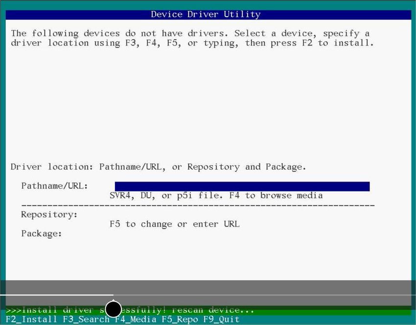
5.10.1 Installing with Solaris Live Media.....................................................................................................24
5.10.2 Installing with Solaris Text Installer..................................................................................................25
5.11 Installing with Citrix XenServer ......................................................................................................................27
5.12 Installing with VMware ..................................................................................................................................27
6 Installing the Driver on an Existing Operating System.....................................................................29
6.1 Download the Driver Package...........................................................................................................................29
6.2 Creating a Driver Disk.......................................................................................................................................29
6.3 Installing on Windows ......................................................................................................................................29
Microsemi Proprietary and Confidential Installation and User's Guide Revision 8 viiiContents
6.4 Installing on Red Hat or CentOS........................................................................................................................30
6.5 Installing on SuSE Linux Enterprise Server........................................................................................................31
6.6 Installing on Oracle Linux..................................................................................................................................33
6.7 Installing on Ubuntu Linux................................................................................................................................34
6.8 Installing on Debian Linux.................................................................................................................................35
6.9 Installing on FreeBSD........................................................................................................................................35
6.10 Installing on Solaris.........................................................................................................................................36
6.11 Installing on Citrix XenServer..........................................................................................................................37
6.12 Installing on VMware......................................................................................................................................38
7 Solving Problems ............................................................................................................................39
7.1 Troubleshooting Checklist.................................................................................................................................39
7.2 Resetting the Adapter ......................................................................................................................................39
Appendix A Using the Microsemi SAS/SATA Configuration Utility......................................................40
A.1 Running the Microsemi SAS/SATA Configuration Utility: Ctrl-A or UEFI/HII?...................................................40
Modifying Controller Settings.................................................................................................................................41
A.3 Out of Band Messaging Settings.......................................................................................................................41
A.4 Viewing Disk Drive Properties..........................................................................................................................42
A.5 Device Information...........................................................................................................................................42
A.6 Identifying a Disk Drive.....................................................................................................................................42
A.7 Updating Drive Firmware.................................................................................................................................43
A.8 Clearing Configuration Meta-data....................................................................................................................43
A.9 Setting the Bootable Device(s) for Legacy Boot Mode.....................................................................................43
A.10 Updating the HBA 1100 controller Firmware.................................................................................................44
A.11 Creating a Support Archive.............................................................................................................................44
Appendix B Installing the SmartPQI Drivers from Source ..................................................................45
B.1 Installation Instructions for Supported Linux OS's............................................................................................45
B.2 Using the Installation DVD as the Repository...................................................................................................47
Appendix C Safety Information...........................................................................................................49
C.1 Electrostatic Discharge (ESD)............................................................................................................................49
Appendix D Technical Specifications...................................................................................................50
D.1 Environmental Specifications...........................................................................................................................50
D.2 DC Power Requirements...................................................................................................................................50
D.3 Current and Power Requirements ...................................................................................................................50
Microsemi Proprietary and Confidential Installation and User's Guide Revision 8 ixAbout This Guide
1 About This Guide
This Installation and User's Guide explains how to install and setup your Adaptec® HBA 1100 Series Host
Bus Adapter, including driver installation and use of the BIOS-based SAS/SATA Configuration utility. It also
provides troubleshooting tips and instructions for flashing the HBA 1100 Series firmware.
These HBA 1100 Series models are described in this guide:
• Adaptec HBA 1100-8i
• Adaptec HBA 1100-4i
• Adaptec HBA 1100-8e
• Adaptec HBA 1100-16i
• Adaptec HBA 1100-24i
• Adaptec HBA 1100-8i8e
• Adaptec HBA 1100-16e
1.1 What You Need to Know Before You Begin
This guide is written for data storage and IT professionals who are responsible for installing, configuring,
and maintaining HBA 1100 Series Host Bus Adapters in computers or servers in a "cloud" or data center
environment. You should be familiar with computer hardware, operating system administration, data
storage devices, and SAS and Serial ATA (SATA) technology.
1.2 Terminology Used in this Guide
Many of the terms and concepts referred to in this guide are known to computer users by multiple names.
This guide uses these terms:
• Host Bus Adapter or HBA (also known as controller, adapter, or I/O card)
• Disk drive (also known as hard disk, hard drive, or hard disk drive)
• Solid State Drive (also known as SSD or non-rotating storage media)
• Enclosure (also known as a storage enclosure, disk drive enclosure, or JBOD)
1.3 How to Find More Information
You can find more information about your HBA 1100 Series Host Bus Adapter by referring to these documents,
available for download at start.microsemi.com.
• Adaptec Host Bus Adapter 1100 Series Command Line Utility User's Guide—Describes how to use the
ARCCONF utility to perform configuration and storage management tasks from an interactive command
line. (ESC-2161614)
• Adaptec HBA 1100 Series Host Bus Adapters Installation and User's Guide (this manual)—Describes
how to install drivers and configure the HBA 1100 Series adapter for initial use. (ESC-2161232)
• Adaptec Host Bus Adapter 1100 Series Release Notes—Includes updated product information and
known issues and limitations. (ESC-2162192)
Microsemi Proprietary and Confidential Installation and User's Guide Revision 8 1Kit Contents and System Requirements
2 Kit Contents and System Requirements
This section lists the contents of your HBA 1100 Series kit and the system requirements for successfully
installing and using your HBA.
2.1 Kit Contents
• HBA 1100 Series adapter
• Low-profile bracket
Note: The latest firmware, drivers, utilities software, and documentation can be
downloaded at storage.microsemi.com. For more information, see Downloading the Driver
Package.
2.2 System Requirements
• PC-compatible computer with Intel Pentium, or equivalent, processor
• 4 GB of RAM minimum
• Available compatible PCIe slot (depending on your adapter model—see the descriptions in About Your
Host Bus Adapter HBAfiguresdescriptions)
• One of these operating systems:
◦ Microsoft® Windows® Server, Windows 10, Windows 8.1, Windows 7
◦ Red Hat® Enterprise Linux
◦ CentOS
◦ SuSE Linux Enterprise Server
◦ Ubuntu Linux
◦ Debian Linux
◦ Oracle Linux
◦ Citrix Xenserver
◦ Solaris
◦ FreeBSD
◦ VMware ESXi
See the Release Notes for a complete list of supported OSs and OS versions.
• USB flash drive or CD burner, for creating driver disks and bootable media
Microsemi Proprietary and Confidential Installation and User's Guide Revision 8 2About Your Host Bus Adapter
3 About Your Host Bus Adapter
This section provides an overview of the features of the HBA 1100 Series adapters.
3.1 Standard Features
• Support for SAS and SATA Hard Disk Drives (HDD), Solid State Drives (SSDs), and SAS tape drives
• UEFI pre-boot BIOS, CTRL-A configuration utility
• Flash ROM for updates to firmware and BIOS
• Up to 8 ports, 12 Gbps SAS I/O and 8 Gbps PCIe I/O with HBA 1100-8i or HBA1100-8e
• Up to 4 ports, 12 Gbps SAS I/O and 8 Gbps PCIe I/O with HBA 1100-4i
• Up to 16 ports, 12 Gbps SAS I/O and 8 Gbps PCIe I/O with HBA 1100-16i
• Up to 24 ports, 12 Gbps SAS I/O and 8 Gbps PCIe I/O with HBA 1100-24i
• SAS 3.0, PCIe 3.0
• Low-profile MD2 form factor
• Mini-SAS HD connectors
• Support for disk drive enclosures with SES 2.x/3.x inband support, TWI, IBPI and SGPIO enclosure
management
• Thermal sensor, with logging capabilities
3.2 Mechanical Information
3.2.1 Board Dimensions
This table shows the board dimensions of the HBA 1100 Series adapters, in inches.
Table 1 • HBA 1100 Series Board Dimensions
Dimension HBA 1100-8i/8e/16i/24i HBA 1100-4i
Height 2.712" 2.712"
Length 6.600" 5.200"
PCB Thickness 0.062" 0.062"
Max Component Height, Top Side 0.570" 0.570"
Max Component Height, Bottom Side 0.105" 0.105"
3.2.2 Heat Sink
HBA 1100 Series adapters include a passive heat sink. For airflow requirements, see Environmental
Specifications on page 50.
3.3 Visual Indicators
LEDs on HBA 1100 Series adapters provide a visual indication of the board hardware status. The LED locations
vary, and may be on the front of the board or back of the board (see HBA 1100 Series LED Locations on
page 4). The LED states are described below in Table 2 • HBA1100 Status LEDs on page 4.
Front panel brackets have three holes for the Heartbeat LED, Fault LED, and Crypto LED.
Microsemi Proprietary and Confidential Installation and User's Guide Revision 8 3About Your Host Bus Adapter
Note: The Crypto LED (near the mounting bracket) is not present on HBA 1100-4i adapter
boards.
Figure 1 • HBA 1100 Series LED Locations
Table 2 • HBA1100 Status LEDs
LED Color Meaning
HEARTBEAT (DS5) Green Heartbeat (blinks once per second when firmware is operating normally)
FAULT (DS7) Amber Hardware Lockup/Fault
CRYPTO (DS1) Green Cryptographic State: always off. HBA 1100 Series adapters do not sup-
port encryption.
AVS_ENB (DS2) Green The controller is operating normally if this LED is on or off: On=Adaptive
Voltage Scaling (AVS) enabled, Off=Adaptive Voltage Scaling (AVS) dis-
abled.
Note: Not supported on HBA1100-16i and HBA1
100-24i adapters.
PAL_DEBUG (DS10) Yellow Reserved: always off. HBA 1100 Series adapters do not support this
feature.
Microsemi Proprietary and Confidential Installation and User's Guide Revision 8 4About Your Host Bus Adapter
3.4 About the Adaptec HBA 1100-8i
The Adaptec HBA 1100-8i is a SAS Host Bus Adapter with these features:
Figure 2 • HBA 1100-8i Features
Form Factor PCIe Low-profile MD2
Bus compatibility PCIe 3.0
PCIe bus width x8
Data transfer rate 12 Gb/s per port
Phys (Unified Serial Ports) 8
Standard memory 32 MB Boot Flash, 256 Kb SEEPROM, 128 KB MRAM
Connectors, internal 1x2 mini-SAS HD x8 (SFF-8643)
Maximum number of disk drives 8 direct-attached (or up to 256 with expanders)
Enclosure Support SES 2.x/3.x inband support, TWI, IBPI and SGPIO
Thermal sensor Inlet ambient temperature, ASIC die temperature, Top-side board ambient tem-
perature, Bottom-side board ambient temperature
Microsemi Proprietary and Confidential Installation and User's Guide Revision 8 5About Your Host Bus Adapter
3.5 About the Adaptec HBA 1100-4i
The Adaptec HBA 1100-4i is a SAS Host Bus Adapter with these features:
Figure 3 • HBA 1100-4i Features
Form Factor PCIe Low-profile MD2 (Smaller than MD2)
Bus compatibility PCIe 3.0
PCIe bus width x8
Data transfer rate 12 Gb/s per port
Phys (Unified Serial Ports) 4
Standard memory 32 MB Boot Flash, 128 Kb SEEPROM, 128 KB MRAM
Connectors, internal 1x1 mini-SAS HD x4 (SFF-8643)
Maximum number of disk drives 4 direct-attached (or up to 256 with expanders)
Enclosure Support SES 2.x/3.x inband support, TWI, IBPI and SGPIO
Thermal sensor Inlet ambient temperature, ASIC die temperature, Top-side board ambient tem-
perature, Bottom-side board ambient temperature
Microsemi Proprietary and Confidential Installation and User's Guide Revision 8 6About Your Host Bus Adapter
3.6 About the Adaptec HBA 1100-8e
The Adaptec HBA 1100-8e is a SAS Host Bus Adapter with these features:
Figure 4 • HBA 1100-8e Features
Form Factor PCIe Low-profile MD2
Bus compatibility PCIe 3.0
PCIe bus width x8
Data transfer rate 12 Gb/s per port
Phys (Unified Serial Ports) 8
Standard memory 32 MB Boot Flash, 256 Kb SEEPROM, 1 Mbit MRAM
Connectors, external 1x2 mini-SAS HD x8 (SFF-8644)
Maximum number of disk drives 8 direct-attached (or up to 256 with expanders)
Enclosure Support SES 2.x/3.x inband support, TWI, IBPI and SGPIO
Thermal sensor Inlet ambient temperature, ASIC die temperature, Top-side board ambient tem-
perature, Bottom-side board ambient temperature
Microsemi Proprietary and Confidential Installation and User's Guide Revision 8 7About Your Host Bus Adapter
3.7 About the Adaptec HBA 1100-8i8e
The Adaptec HBA 1100-8i8e is a SAS Host Bus Adapter with these features:
Figure 5 • HBA 1100-8i8e Features
Form Factor PCIe Low-profile MD2
Bus compatibility PCIe 3.0
PCIe bus width x8
Data transfer rate 12 Gb/s per port
Phys (Unified Serial Ports) 16
Standard memory 32 MB Boot Flash, 128 Kb SEEPROM, 128 KB MRAM
Connectors, internal 2 mini SAS HD x4 (SFF-8644) and 2 mini SAS HD x4 (SFF-8643)
Maximum number of disk drives 16 direct-attached (or up to 256 with expanders)
Enclosure Support SES 2.x/3.x inband support, TWI, IBPI and SGPIO
Thermal sensor Ambient temperature, ASIC die temperature
Microsemi Proprietary and Confidential Installation and User's Guide Revision 8 8About Your Host Bus Adapter
3.8 About the Adaptec HBA 1100-16e
The Adaptec HBA 1100-16e is a SAS Host Bus Adapter with these features:
Figure 6 • HBA 1100-16e Features
Form Factor PCIe Low-profile MD2
Bus compatibility PCIe 3.0
PCIe bus width x8
Data transfer rate 12 Gb/s per port
Phys (Unified Serial Ports) 16
Standard memory 32 MB Boot Flash, 128 KB MRAM, 128 Kb SEEPROM
Connectors, internal 4 mini SAS HD x4 (SFF-8644)
Maximum number of disk drives 16 direct-attached (or up to 256 with expanders)
Enclosure Support SES 2.x/3.x inband support, TWI, IBPI and SGPIO
Thermal sensor Ambient temperature, ASIC die temperature
Microsemi Proprietary and Confidential Installation and User's Guide Revision 8 9About Your Host Bus Adapter
3.9 About the Adaptec HBA 1100-16i
The Adaptec HBA 1100-16i is a SAS Host Bus Adapter with these features:
Figure 7 • HBA 1100-16i Features
Form Factor PCIe Low-profile MD2
Bus compatibility PCIe 3.0
PCIe bus width x8
Data transfer rate 12 Gb/s per port
Phys (Unified Serial Ports) 16
Standard memory 32 MB Boot Flash, 128 Kb SEEPROM, 128 KB MRAM
Connectors, internal 4 mini-SAS HD x4 (SFF-8643)
Maximum number of disk drives 16 direct-attached (or up to 256 with expanders)
Enclosure Support SES 2.x/3.x inband support, TWI, IBPI and SGPIO
Thermal sensor Ambient temperature, ASIC die temperature
Microsemi Proprietary and Confidential Installation and User's Guide Revision 8 10About Your Host Bus Adapter
3.10 About the Adaptec HBA 1100-24i
The Adaptec HBA 1100-24i is a SAS Host Bus Adapter with these features:
Figure 8 • HBA 1100-24i Features
Form Factor PCIe Low-profile MD2
Bus compatibility PCIe 3.0
PCIe bus width x8
Data transfer rate 12 Gb/s per port
Phys (Unified Serial Ports) 24
Standard memory 32 MB Boot Flash, 128 Kb SEEPROM, 128 KB MRAM
Connectors, internal 6 mini-SAS HD x4 (SFF-8643)
Maximum number of disk drives 24 direct-attached (or up to 256 with expanders)
Enclosure Support SES 2.x/3.x inband support, TWI, IBPI and SGPIO
Thermal sensor Ambient temperature, ASIC die temperature
Microsemi Proprietary and Confidential Installation and User's Guide Revision 8 11Installing the Controller and Disk Drives
4 Installing the Controller and Disk Drives
This section explains how to install your HBA 1100 Series adapter in a computer cabinet or server and
connect it to internal and external disk drives.
4.1 Before You Begin
• Read Safety Informationsafety information.
• Familiarize yourself with your HBA's physical features (see Standard Featuresadapters standard features).
• Ensure that you have the right number of disk drives for your application (see Selecting Disk Drives
and Cables adapters disk drivesdisk drives).
4.2 Selecting Disk Drives and Cables
4.2.1 Disk Drives
The HBA 1100 Series supports SAS and SATA disk drives, Solid State Drives (SSDs), and SAS tape drives.
For more information about compatible disk drives, refer to To be supplied.
4.2.2 Cables
Depending on your HBA model and application requirements, you can use any of the cables listed below.
For more information about cabling options for your HBA 1100 Series adapter, visit To be supplied.
Note: We recommend using Microsemi Adaptec SAS cables only.
SAS HD Cables
Internal Mini SAS HD to SAS HD (SFF-8643 to SFF-8643)—Connects
to a backplane or enclosure.
External Mini SAS HD to SAS HD (SFF-8644 to SFF-8644)—Connects
to a backplane or enclosure.
Microsemi Proprietary and Confidential Installation and User's Guide Revision 8 12Installing the Controller and Disk Drives
4.3 Installing the Host Bus Adapter
This section describes how to install the HBA 1100 Series adapter into your computer cabinet or server.
HBA 1100 Series adapters have two configurations:
• Adapters with internal connectivity
• Adapters with external connectivity
Follow the steps below to install your HBA and connect internal or external storage devices.
1. Turn off your computer and disconnect the power cord and any network cables. Open the cabinet,
following the manufacturer's instructions.
2. Select an available PCIe expansion slot that's compatible with your HBA and remove the slot cover, as
shown in the figure below. (To check PCIe bus compatibility of your HBA, see About Your Host Bus
Adapter HBAfiguresdescriptions.)
Caution: Touch a grounded metal object before handling the adapter.
3. Insert the HBA into the expansion slot and press down gently but firmly until it clicks into place. When
installed properly, the adapter should appear level with the expansion slot.
Caution: Be sure to handle the adapter by its bracket or edges only. Apply pressure
only on the edges when inserting the card into expansion slot.
Microsemi Proprietary and Confidential Installation and User's Guide Revision 8 13Installing the Controller and Disk Drives
4. Secure the bracket in the expansion slot, using the retention device (for instance, a screw or lever)
supplied with your computer.
5. Connect mini-SAS HD cables between the HBA and internal or external storage devices.
• For a HBA with internal ports, connect mini-SAS HD cables between the HBA and internal disk drives
or enclosures.
• For a HBA with with external ports, connect mini-SAS HD cables between the HBA and external
disk drives or enclosures.
External Ports,
Front view
6. Close your computer cabinet, reconnect the power cord and network cables, then power up the system.
Microsemi Proprietary and Confidential Installation and User's Guide Revision 8 14Installing the Driver and an Operating System
5 Installing the Driver and an Operating System
This chapter explains how to install the Microsemi SmartPQI controller driver and an operating system on
a bootable volume. It assumes that the HBA 1100 controller is installed in a computer or server.
Note:
• For information about building the SmartPQI drivers from source, see Installing the
SmartPQI Drivers from Source on page 45.
5.1 Download the Driver Package
Complete these steps to download the drivers for your operating system(s):
1. Open a browser window, then type start.microsemi.com in the address bar.
2. Enter your product or adapter model number, then select HBA 1100.
3. Select your operating system version, for instance, Microsoft Windows Server 2016 x64 or Red Hat
Enterprise Linux 7; then select the appropriate driver from the list.
4. Download the controller driver package (zip file archive).
5. When the download completes, extract the package contents to a temporary location on your machine.
Each driver is stored in a separate folder (\windows 2016, \rhel7, \rhel6, and so on).
Note: See the Release Notes for a complete list of available driver files.
5.2 Creating a Driver Disk
Create a driver disk by completing the steps below. You will need a USB flash drive to complete this task.
Note: For VMware, see Installing with VMware on page 27.
1. Change to the driver directory for your operating system version.
2. Write the driver binary file to a USB flash drive.
For example, if the USB drive is /dev/sdc on the Linux system, type (where #.#.#-### is the build
number):
Option Description
RHEL 7 dd if=smartpqi-#.#.#-###.rhel7u2.x86_64.dd of=/
dev/sdc
SLES 12 dd if=smartpqi-#.#.#-###.sles12sp1.x86_64.dd of=/
dev/sdc
Ubuntu dd if=smartpqi-#.#.#-###_ubuntu16.04_x86_64.img
of=/dev/sdc
Debian Linux dd if=smartpqi-#.#.#-###_debian8.8_x86_64-Boot.tgz
of=/dev/sdc
Note: See the Release Notes for the latest build number.
3. Remove and label the driver disk.
4. Continue the installation with the instructions for your operating system.
Microsemi Proprietary and Confidential Installation and User's Guide Revision 8 15Installing the Driver and an Operating System
5.3 Installing with Windows
Note:
Use the following procedure for all supported Windows versions. You will need your
Windows Installation DVD (or equivalent virtual media/iso image) to complete this task.
To install the controller SmartPQI driver while installing Windows:
1. Insert the Windows installation DVD, then restart the computer.
2. Follow the on-screen instructions to begin the Windows installation.
3. When prompted to specify a location for Windows, select Load Driver.
4. Insert the USB driver disk, browse to the driver location, then click Ok.
5. When prompted to select the driver to install, click Next.
6. Click Next again to accept the default partition configuration.
7. Follow the on-screen instructions to complete the installation.
5.4 Installing with Red Hat Linux or CentOS
To install the controller SmartPQI driver while installing Red Hat Linux or CentOS, follow the steps in the
sections below.
RHEL7 Update 3 Installation and Above
To install the RHEL7 Update 3 driver with a Linux system:
1. Install the Linux system using the inbox smartpqi driver.
2. After the installation completes, install the latest smartpqi driver rpm by using the following command
(where #.#.#-### is the build number):
rpm –ivh kmod-smartpqi-#.#.#-###.rhel7u3.x86_64.rpm
RHEL7 Installation
Note: The following steps apply to all updates of RHEL 7 prior to Update 3. The example
illustrated here represents the steps for Update 2. Modify the filename of the installation
archive to match the appropriate update version in the appropriate fields.
To install the RHEL7 driver with a Linux system:
1. Copy the RHEL driver binary image to the USB key; see Creating a Driver Disk on page 15.
2. Power-on the system.
3. Insert the RHEL7 DVD image from a media source.
4. Boot the RHEL installation.
5. Type "e" to edit the grub entry and append "modprobe.blacklist=aacraid inst.dd".
Note: This will cause the line to wrap. The editor adds the "\" automatically.
6. Insert the USB device, then type CTRL+X to boot.
Note: If the installer does not display the driver update media, type "r" and Enter on
your keyboard to refresh the list.
a. Select the device in the list with the label "OEMDRV":
Microsemi Proprietary and Confidential Installation and User's Guide Revision 8 16Installing the Driver and an Operating System
The installer presents a driver (smartpqi rpm) to install.
b. Type "1" on your keyboard and Enter to select the driver update.
c. Type "c" and Enter to continue.
Note: It is recommended to remove the USB device once the driver update has
been extracted, for example:
DD: Extracting files....
RHEL6 Update 9 Installation and Above
To install the RHEL6 Update 9 driver with a Linux system:
1. Install the Linux system using the inbox smartpqi driver.
2. After the installation completes, install the latest smartpqi driver rpm by using the following command
(where #.#.#-### is the build number):
rpm –ivh smartpqi-kmp-default-#.#.#-###.rehl6u9.x86_64.rpm
RHEL6 Installation
To install the RHEL6 driver with a Linux system:
1. Copy the RHEL driver binary image to the USB key; see Creating a Driver Disk on page 15.
2. Power-on the system.
3. Insert the RHEL6 DVD image from a media source.
4. Boot the RHEL installation.
5. Press the Esc key when a grub entry appears with a countdown.
6. Type "e" to edit the grub entry
7. Type "e" again and append "blacklist=aacraid dd".
8. Press the Enter key and type "b".
9. Select Yes to specify that the driver disk is available.
10. Select the sd device.
Note: The device name of the driver update disk may vary.
11. Select No when the "More Driver Disks?" dialog appears.
Note: It is recommended to remove the USB device at this step.
12. Proceed with the normal installation.
5.5 Installing with SuSE Linux Enterprise Server
To install the controller SmartPQI driver while installing SuSE Linux, follow the steps in the sections below.
Installing with SLES 12 SP2 and Above
Follow these steps to install the driver while installing SLES 12 SP2:
1. Install the Linux system using the inbox smartpqi driver.
Microsemi Proprietary and Confidential Installation and User's Guide Revision 8 17Installing the Driver and an Operating System
2. After the installation completes, install the latest smartpqi driver rpm by using the following command
(where #.#.#-### is the build number):
rpm -ivh smartpqi-ueficert-#.#.#-###.sles12sp2.x86_64.rpm
rpm -ivh smartpqi-kmp-default-#.#.#-###.sles12sp2.x86_64.rpm
Installing with SLES 12
Follow these steps to install the driver while installing SLES 12:
1. Copy the SLES driver binary image to the USB key; see Creating a Driver Disk on page 15.
2. Power-on the system.
3. Insert the SLES 12 DVD image from a media source.
4. Boot the SLES installation.
5. Type "e" to edit the grub entry when the SLES installation menu is displayed and append
"broken_modules=aacraid driverupdate=1".
6. Insert the USB device and type CTRL+X to boot.
The installation of the driver will start automatically.
7. Make sure that the controller is listed in the "Please choose the Driver Update medium" dialog box.
Note: If you do not see the controller, a driver installation error occurred. This can
happen if the driver was built against a different kernel version of the OS than the
installed media.
Note: It is recommended to remove the driver update USB device.
8. Click Back and continue with the normal installation procedure.
Installing with SLES 11
Follow these steps to install the driver while installing SLES 11:
1. Copy the SLES driver binary image to the USB key; see Creating a Driver Disk on page 15.
2. Power-on the system.
3. Insert the SLES 11 DVD image from a media source.
4. Boot the SLES installation.
5. Type "e" to edit the grub entry and append "broken_modules=aacraid driverupdate=1".
6. Insert the USB device and type CTRL+X to boot.
The installation of the driver will start automatically.
7. Make sure that the controller is listed in the "Please choose the Driver Update medium" dialog box.
Note: If you do not see the controller, a driver installation error occurred. This can
happen if the driver was built against a different kernel version of the OS than the
installed media.
Note: It is recommended to remove the driver update USB device.
8. Click Back and continue with the normal installation procedure.
Microsemi Proprietary and Confidential Installation and User's Guide Revision 8 18Installing the Driver and an Operating System
5.6 Installing with Oracle Linux
To install the controller SmartPQI driver while installing Oracle Linux, follow the steps in the sections below.
Installing with Oracle Linux 7.3 and Above
Note:
1. The Oracle Linux 7.3 base kernel includes a smartpqi driver. The UEK kernel does not.
2. If using the UEK boot ISO for installation, you will need to use the driver update process
described in the Oracle Linux 7.2 installation section.
Follow these steps to install the driver while installing Oracle Linux 7.3:
1. Install the Linux system using the inbox smartpqi driver.
2. On reboot, select the Oracle Linux 7.3 base kernel from the grub menu to boot. Grub will attempt to
default to the UEK kernel.
3. After the installation completes, install the latest smartpqi driver rpm for the kernel you intend to run
(where #.#.#-### is the build number):
Base Kernel: rpm –ivh kmod-smartpqi-#.#.#-###.ol7u3.x86_64.rpm
UEK Kernel: rpm –ivh kmod-smartpqi-uek-#.#.#-###.ol7u3.x86_64.rpm
Installing with Oracle Linux 7.2
Follow these steps to install the driver while installing Oracle Linux 7.2:
1. Copy the Oracle Linux driver binary image to the USB key; see Creating a Driver Disk on page 15.
2. Power-on the system.
3. Insert the Oracle Linux 7 DVD image from a media source.
4. Boot the Oracle installation.
5. Type "e" to edit the grub entry when the Oracle Linux installation menu is displayed and append
"modprobe.blacklist=aacraid inst.dd".
6. Insert the USB device, then type CTRL+X to boot.
The installation of the driver will start automatically.
7. Complete the following steps:
a. Select the device in the list with the label "OEMDRV".
The installer will present a driver (smartpqi rpm) to install.
b. Type "1" on your keyboard, then press Enter to select the driver update.
c. Type "c", then press Enter to continue.
Note: We recommend that you remove the USB device once you see that the
driver update has been extracted; for example: "DD: Extracting files...".
d. Click Continue and follow the prompts for a normal install.
Note: The driver update will install the smartpqi driver for the Oracle Linux 7.2
base kernel only.
Microsemi Proprietary and Confidential Installation and User's Guide Revision 8 19Installing the Driver and an Operating System
8. On reboot, select the Oracle Linux 7.2 base kernel from the grub menu to boot. Grub will attempt to
default to the UEK kernel.
9. After the installation completes, install the latest smartpqi driver rpm for the UEK kernel (where #.#.#-###
is the build number):
UEK Kernel: rpm –ivh kmod-smartpqi-uek-#.#.#-###.ol7u2.x86_64.rpm
5.7 Installing with Ubuntu Linux
To install the controller SmartPQI driver while installing Ubuntu Linux:
Note: The following instructions apply to Ubuntu Server only.
1. Copy the Ubuntu driver binary image to the USB key; see Creating a Driver Disk on page 15.
2. Power-on the system.
3. Insert the Ubuntu CD/DVD image from a media source.
4. Boot the Ubuntu installation.
5. Type "e" to edit the grub entry when the Ubuntu installation menu is displayed.
6. Append "modprobe.blacklist=aacraid" after the “--“ on the line starting with “Linux”.
7. Insert the USB device, then type CTRL+X to boot.
The driver installation will start automatically.
8. When the installer presents a dialog regarding detection of a virtual driver disk, select yes. Then proceed
with standard installation process.
Note: It is recommended to remove the driver update USB device when the installer
reaches the “Configure the network” screen.
9. At the "Finish the installation/Installation complete" screen, from a back terminal blacklist the aacraid
driver before rebooting using the following steps:
a. Press Alt + F2.
b. Type the following commands:
chroot /target
echo “blacklist aacraid” > /etc/modprobe.d/install-aacraid.conf
depmod `uname –r`
update-initramfs –u
exit
c. Press Alt + F1 to return to the installation screen.
10. Press Continue to reboot the system.
11. Install the smartpqi DKMS package (smartpqi-dkms_#.#.#-###_all.deb) by using the following
commands (where #.#.#-### is the build number):
Microsemi Proprietary and Confidential Installation and User's Guide Revision 8 20Installing the Driver and an Operating System
Note: The smartpqi DKMS package rebuilds the smartpqi driver automatically
whenever the kernel on the system is updated. This ensures that you have a smartpqi
driver to support the new kernel.
apt-get update
apt-get –f install build-essential dkms
dpkg -i smartpqi-dkms_#.#.#-###_all.deb
5.8 Installing with Debian Linux
To install the controller SmartPQI driver while installing Debian Linux:
1. Copy the Debian driver binary image (smartpqi.ko) to the USB key; see Creating a Driver Disk on page
15.
2. Boot the Debian installation from the DVD or media source.
3. Type "e" to edit the boot entry when the Debian installation menu is displayed.
4. Append "modprobe.blacklist=aacraid" after the “--“ on the line starting with “Linux”.
5. Type CTRL+X to boot.
6. Proceed with standard installation process until the installer reaches the “Configure the network” screen.
7. Press CTRL+ALT+F2.
8. Insert the Debian driver USB key.
9. Assuming the USB drive is assigned to /dev/sda1, type the following commands to begin loading the
driver:
Note: Type fdisk -l to determine the USB device assignment.
mkdir /SMARTPQI
mount -t vfat /dev/sda1 /mnt
cp -R /mnt/* /SMARTPQI
umount /mnt
10. Remove the Debian driver USB key.
11. Copy the driver to /lib/modules and load driver module:
Note: The following steps assume you are installing Debian 8.8 64-bit, using kernel
3.16.0-4.
mkdir -p /lib/modules/3.16.0-4-amd64/kernel/drivers/scsi/smartpqi
cp -f /SMARTPQI/smartpqi.ko
/lib/modules/3.16.0-4-amd64/kernel/drivers/scsi/smartpqi/smartpqi.ko
depmod -a `uname -r`
modprobe smartpqi
12. To return to the graphical install, press CTRL+ALT+F5; to return to a non-graphical install, press ALT+F1.
Note: Do not press Continue at the end of the installation until you complete Step [
13 ] and Step [ 14 ] .
13. When prompted to reboot the system, press CTRL+ALT+F2 to switch to the console.
Microsemi Proprietary and Confidential Installation and User's Guide Revision 8 21Installing the Driver and an Operating System
14. Type the following commands to complete the driver installation:
mkdir -p /target/lib/modules/3.16.0-4-amd64/kernel/drivers/scsi/smartpqi
cp -f /SMARTPQI/smartpqi.ko
/target/lib/modules/3.16.0-4-amd64/kernel/drivers/scsi/smartpqi/smartpqi.ko
chroot /target
depmod -a `uname -r`
echo “blacklist aacraid” > /etc/modprobe.d/aacraid-blacklist.conf
update-initramfs -u -v
exit
15. To return to a graphical install, press CTRL+ALT+F5; to return to a non-graphical install, press ALT+F1.
16. Reboot the system.
17. Install the smartpqi DKMS package (smartpqi-dkms_#.#.#-###_all.deb) by using the following
commands (where #.#.#-### is the build number):
Note: The smartpqi DKMS package rebuilds and activates the smartpqi driver
automatically any time the kernel on the system is updated. This insures you have a
smartpqi driver to support the new kernel.
apt-get install build-essential dkms
dpkg -i smartpqi-dkms_#.#.#-###_all.deb
5.9 Installing with FreeBSD
To install the controller SmartPQI driver while installing FreeBSD:
1. Copy the driver module (smartpqi.ko) to a USB drive.
Disk partition the USB key, using gpart on a unix system.
For example:
# gpart create -s GPT da1
# gpart add -t freebsd-ufs da1
# newfs /dev/da1p1
# mount /dev/da1p1 /mnt
# cp smartpqi.ko /mnt
2. Insert the USB driver disk.
3. Insert the FreeBSD Installation disk into the CD/DVD drive and boot from it.
4. From the FreeBSD boot menu, press Escape to launch the boot loader prompt.
5. Perform the following steps at the boot loader prompt:
a. Check all the present modules by executing following command.
# lsmod
Expected Output: It will show all the present modules.
b. Unload the kernel module by executing the following command:
# unload
Microsemi Proprietary and Confidential Installation and User's Guide Revision 8 22You can also read