TEN YEARS NETWORK DEVELOPMENT PLAN - PERIOD 2021 2030 - Investment and Development Division - Мепсо
←
→
Page content transcription
If your browser does not render page correctly, please read the page content below
Investment and Development Division

   TEN YEARS NETWORK
   DEVELOPMENT PLAN
   PERIOD 2021 – 2030

   October, 2020

Ten Years Network Development Plan, period 2021-2030

         Title:        TEN YEARS NETWORK DEVELOPMENT PLAN
                       PERIOD 2021 – 2030

         Authors:      Strategic Planning and Development Analyses Unit
                       Connections Unit

                                                                          ii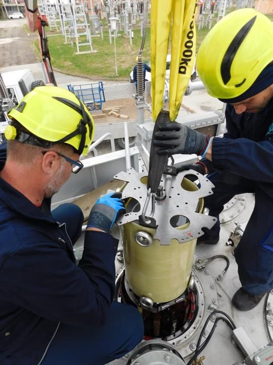
Ten Years Network Development Plan, period 2021-2030

Context
      Introduction ....................................................................................... 5
      Condition of the Transmission Grid in 2020 ................................................. 7
      Projects Completed in 2020 ................................................................... 11
     3.1. Reconstruction and Revitalization of Transmission Lines ............................. 11
     3.2. Reconstruction and Revitalization of Substations ...................................... 11
     3.3. Projects for power system modernization ............................................... 11
4.    New Interconnectons towards the Neighbors .............................................. 13
     4.1. 400 kV Interconnection MK – AL ........................................................... 13
      4.1.1.     Technical Specifications .............................................................. 13
      4.1.2.     Financial and Economic Parameters................................................. 15
      4.1.3.     Project Implementation ............................................................... 16
5.    Measures and Investments in the Period 2021-2030 ..................................... 18
     5.1. Northern Region of the Transmission Network .......................................... 18
     5.2. Western Region of the Transmission Network ........................................... 19
     5.3. Eastern Region of the Transmission Network ........................................... 20
6.    Reconstruction and Revitalization within the Transmission Network................. 22
     6.1. Reconstruction and Revitalization of Transmission Lines ............................. 22
     6.1.1. Reconstruction of Transmission Lines ................................................... 22
             Revitalization of Transmission Line ...................................................... 24
      6.2.       Reconstruction and Revitalization of Substations ................................. 24
      6.2.1.     Revitalization of High-voltage Equipment .......................................... 25
      6.2.2.     Reconstruction of Switchyard Kratovo .............................................. 25
      6.2.3.     Revitalization of the 400/110 kV Substations
                 (SS Skopje 4, SS Bitola 2, SS Dubrovo) .............................................. 26
      6.2.4.     Revitalization of SS Veles and SS Kavadarci 1...................................... 26
     6.3. Revitalization/Reconstruction of Control Systems in Substations .................... 27
      6.3.1.     Revitalization and Modernization of the Control System in SS Samokov ....... 27
      6.3.2.     Revitalization and Modernization of the Control System in SS Strumica1 ..... 27
      6.3.3.     Revitalization and Modernization of the Control System in SS Sushica......... 27
7.    Modernization of the Power System ......................................................... 29
             Telecommunication Equipment and Remote Monitoring of the Substations ........ 29
     7.2. Optical Ground Wire Connection .......................................................... 30
     7.3. Balkan Digital Highway ..................................................................... 30
     7.4. Procurement and Installation of OPGW in 400 kV TL Skopje 4 - Bitola 2 ........... 31

                                                                                                         iii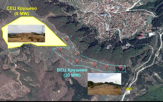
Ten Years Network Development Plan, period 2021-2030

     7.5. Dynamic Line Rating -DLR .................................................................. 32
     7.6. Voltage Regulation Technology ........................................................... 32
     7.7. Procurement and Installation of New SCADA/EMS System ............................ 32
     7.8. Data Room .................................................................................... 32
     7.9. ENTSO-E Electronic Highway in NDC and BDC ........................................... 33
     7.10. Smart Maintenance and Asset Management ............................................. 33
8.    Power System Research and Development ................................................. 33
     8.1. CROSSBOW ................................................................................... 33
     8.2. TRINITY ....................................................................................... 34
     8.3. Regional Feasibility Study on Voltage Profile Improvement .......................... 35
     8.4. Study on Network Development ........................................................... 35
     8.5. Studies on Integration of RES .............................................................. 35
     8.6. Strengthening the Transmission Network
          in the Southeast Region of North Macedonia ............................................ 36
9.    Connections of New Users to the Transmission Network ................................ 37
     9.1. Connection of Production Capacities to the Transmission Network ................. 37
      9.1.1.    Connection of WPP Bogoslovec ...................................................... 37
      9.1.2.    Connection of WPP Demir Kapija .................................................... 38
      9.1.3.    Connection of WPP Miravci ........................................................... 39
      9.1.4.    Connection of WPP Krushevo and PVPP Krushevo ................................. 40
      9.1.5.    Connection of WPP Oslomej 1 and 2 PVPP Oslomej (PPP) ....................... 40
      9.1.6.    Connection of PVPP Bitola ............................................................ 41
      9.1.7.    Connection of PVPP Tikvesh .......................................................... 42
     9.2. Connection of Distribution Substations to the Transmission Network ............... 42
      9.2.1.    Connection of Second Transformer in SS Ovche Pole ............................. 42
     9.3. Connection of Industrial Consumers to the transmission Network ................... 43
      9.3.1.    Connection of Cranfield Foundry .................................................... 43
      9.3.2.    Connection of IMG Trade.............................................................. 44
      9.3.3.    Connection of Deposit Plavica – Kratovo............................................ 45
10. Projects Realization in the Period 2021 - 2030 ........................................... 47
11. Complex Energy Projects Implementation ................................................. 50
12. Costs for Connection of New users........................................................... 53
13. Configuration of the Transmission Grid in 2030 ........................................... 54

                                                                                                          iv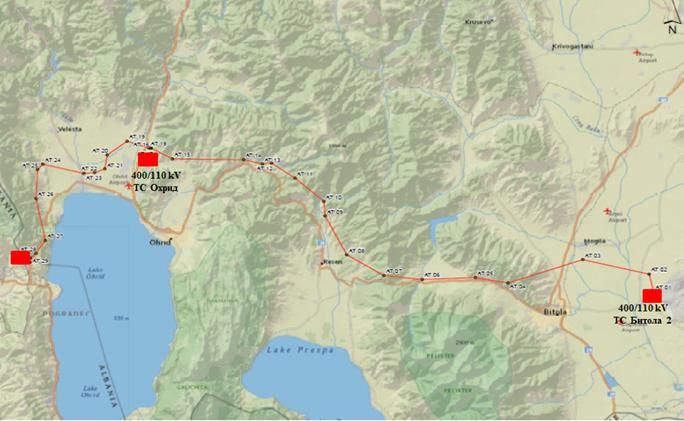
Ten Years Network Development Plan, period 2021-2030

        INTRODUCTION
MEPSO as electricity transmission system operator, pursuant to Article 83 from the Law on
Energy (Official Gazette of the Republic of Macedonia No.96/18 and Official Gazette of the
Republic of Macedonia No.96/19) is obliged to prepare а plan for development of the power
system for the subsequent period of 10 (ten) years, whose content has to be in compliance
with the Grid Code for electricity transmission.
MEPSO in 2016/2017 carried out a study on the development of the transmission grid titled
“Study on development concepts of the transmission grid in different regions for a long-term
horizon” that represents an update/definition of the development plans for the electric
power system (EPS), as MEPSO’s obligation in correspondence to the legislation of the state.
The Study analyses future possible working conditions and it is prepared by use of a
deterministic approach with more scenarios. The scenarios are defined for different time
horizons (2020, 2025, 2030, and 2040) depending on factors like construction of power
plants, system loading, hydrology, engagement of the plants that use renewable energy
sources (RES – especially wind power plants), construction of power plants in the distribution
network, etc. The final aim of the analysis of more scenarios is to fulfil the following basic
principles:

   -   reliable electricity security

   -   reliable accessibility and capacity of the Macedonian transmission network for a
       uninterrupted flow of the activities of all of the participants in the electricity
       market (producers, traders, and suppliers, as well as other subjects);

   -   connection of new consumers to the transmission grid under equal, transparent,
       and non-discriminatory conditions;

   -   connection with the neighbouring transmission system operators, hence enabling
       connection to the neighbouring electricity market operators;

   -   integration of new power plants that use RES.

The future configuration of the Macedonian transmission network should be sufficiently
flexible and resilient, in order to enable accomplishment of the above-mentioned principles
with as little insecurity as possible. To provide the prior, it is necessary to:

   -   Continuously invest in the reconstruction and revitalization of the deteriorated
       elements of the transmission grid;
   -
   -   Invest in construction of new facilities in the transmission grid (transmission lines,
       transformers (TR), information technology infrastructure, etc.) based on the
       criteria prescribed in the Grid Code;
   -
   -   Invest in undertakings that will enable better utilization of the exciting and
       construction of new necessary cross-border capacities;
   -
   -   Use modern technologies for transmission of electricity, such as utilization of new
       low sag conductors during revitalization and increase of the transmission capacity in
       the existing transmission lines (TL), possible installation of units based on power
       electronics (FACTS), possible installation of face shifting power transformers
       (control over the active power flow), etc.

                                                                                          5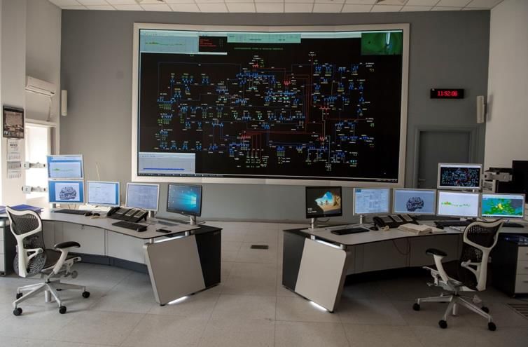
Ten Years Network Development Plan, period 2021-2030

       Constantly promote and improve human resources due to obligational participation
       in the European processes under ENTSO-E and participation in other international
       organizations (CIGRE, IEEE, etc.).

The greatest risks for a successful realization of the previously listed principles and planned
activities are the uncertain flows in the economy, constraints upon physical and regional
planning and ecological demands, insecurities regarding the construction of new generation
facilities, and uncertainties in the stable financing of all necessary activities. MEPSO
prepares a study or environmental impact assessment with detailed analysis for all
infrastructural projects as per the Law on Construction. In the procedures of preparation
and realization of all projects, MEPSO pays close attention to protection of the flora and
fauna.
MEPSO in September 2019 prepared a Study on reconstruction/revitalization of the
transmission grid. Taking into consideration that a great number of the transmission lines of
the Macedonian transmission network were built 40-50 years ago, one may expect that after
2020, a large number of the lines will be candidates for reconstruction/revitalization.
Therefore, when making a schedule for reconstruction of the lines, besides the age of the
lines, their significance for the secure operation of the transmission network should be taken
into consideration, as well. Consequently, the focus of this Strategy was pointed towards
two key factors:
    - preparation of database about the condition of the functional units of the
         transmission lines which resulted in estimation for the condition and the urgency of
         undertakings on certain parts, thus forming priority list; and

   -   determination of the methodology that includes a schedule of works set up in given
       periods (2025-2030, 2030-2035, 2035-2040), created by deterministic approach,
       therefore carefully planning the schedule paying attention to all security criterion
       for grid operation.

So, the schedule of works on the lines during the periods 2025-2030, 2030-2035, 2035-2040
was prepared by taking into consideration the condition of the transmission lines, as well as
their significance to the power system. Additionally, the recommendations from the already
prepared development plans and studies in MEPSO were considered. The geographical
connection of the lines was also acknowledged.
Although the average age of the transmission lines is relatively high and it is estimated to be
42 years, almost 2/3 of them have above-average good grades regarding their condition
which indicates that they have been properly maintained. The total amount of investments
for the three periods is 47.2 million euros, while the complete length of the transmission
lines suggested for reconstruction/revitalization is 560 km. The mean value of the
investments is 15.8 million euros, while the mean length is 187.5 km. Both the investments
and lengths are equally allocated in periods, at an interval from ±10% from the mean value.
The development plan for the transmission grid for the period from 2021-2030 represents an
updated version of the analysis and results from the two studies, giving a display of the state
of the completed projects, projects which are in implementation phase, and the necessary
measures and investments that need to be undertaken in the next 10 years.

                                                                                          6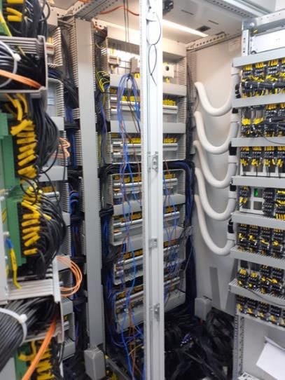
Ten Years Network Development Plan, period 2021-2030

        CONDITION OF THE TRANSMISSION GRID IN 2020

A well-developed transmission grid with a large number of rings (contours) on two voltage
levels: 110 kV and 400 kV is a key for the integration of producers and consumers in the
power system.
The transmission grid consists of transmission lines, transformer substations as well as the
overall accompanying primary and secondary high voltage equipment. Table 1 shows the
given lengths of transmission lines in the transmission grid by voltage level, while Table 2
shows the number of transformer substations by voltage levels.
Table 1. Length of the transmission network by voltage level

  Voltage level [kV]        110 kV           400 kV

  Length [km]               1544,7           577,033

Table 2. Number of transformer substations by voltage level

  Nominal voltage ratio     110/x kV         400/110 kV

  Number of substations     73               5

The 400 kV transmission lines are the backbone of the Macedonian transmission grid. They
form a 400 kV ring comprised of three transmission lines that connect the largest
consumption concentration located in the northern part of the country with the largest
production facilities located in the southeast region of the country. Moreover, the 400 kV
transmission lines are used for interconnection between the neighbouring power systems.
The transmission grid of 110 kV is the most outspread and the most developed one. It
connects the large hydroelectric power plants and thermal power plants, all of the larger
populated places, as well as the industrial parks. The connection between the 400 kV and
110 kV transmission networks is realized via five substations: SS Skopje 4, SS Skopje 5, SS
Bitola 2, SS Dubrovo, and SS Shtip.
The Macedonian power system is connected with the neighbouring systems via 400 kV
interconnections. With the market development, the interconnections acquire a role of
major energy corridors through which a significant number of electricity transactions are
realized.
On the northern side, towards Kosovo operates the 400 kV transmission line SS Skopje 5 - SS
Ferizaj (Uroshevac), while with Serbia the connection is done via the 400 kV transmission
line SS Shtip-SS Vranje. In the past, two more 220 kV transmission lines operated SS Skopje
1 - SS Kosovo A, as well as 110 kV transmission line SS Skopje 1 - SS Shari. Since 1999, these
transmission lines have been out of operation due to damage. The development plans do not
foresee their reconstruction, but only the corridors will be used for future construction of
transmission lines.
The Macedonian power system is best connected with Greece. The Macedonian and Greek
power systems are interconnected with two 400 kV interconnecting transmission lines: SS
Bitola 2 - SS Lerin (Florina) and SS Dubrovo - SS Solun (Thessaloniki).
Towards the eastern side, after the 400 kV transmission line SS Shtip – Chervena Mogila was
built, we have commenced mutual and synchronized collaboration with the Bulgarian power
system. Until then, between the systems had occurred occasional electricity exchanges in
an “islanding” operation, using the two 110 kV transmission lines SS Kriva Palanka –SS

                                                                                         7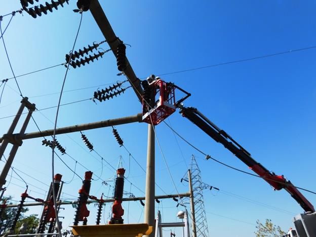
Ten Years Network Development Plan, period 2021-2030

Skakavica and SS Sushica-SS Petrich. Currently, both of the 110 kV transmission lines are still
functioning but in an island mode.

Figure 1.      Topology of the transmission network in 2020
The following figures are of illustrated parameters from operating regimes with high loads
in the transmission network.
The transmission network has good voltage profile (Figure 2), the voltages from the 110 kV
nodes are close in value to the nominal voltage. A slightly lower voltage profile appears in
the southeast region, Ohrid - Prespa. The problem arises from the long serial connection
Globochica – Struga – Ohrid 1 – Ohrid 2 – Resen – Bitola 4 where a huge voltage outage
appears. The voltage profiles will improve after the construction of the new 400/110 kV SS
Ohrid (see 0 and 4). Similarly, the voltages are lower in the southeast region, Valandovo –
Strumica due to a lack of generation facilities that support the voltage profile. The project
for strengthening of the transmission network in the southeast region and construction of
new RES (see 5.3) will mend the voltage conditions.
There are no transmission lines in the network whose load exceeds the permitted voltage
levels in a normal working regime (without outages). The 110 kV lines which transmit
electricity from the power plants and/or main 400/110 kV generation busbars towards the
remaining consumers in the network are the most loaded.
Table 3 depicts the values of the short-circuit currents in different nodes from the
transmission network. High voltage values of short-circuit currents, around 30 kA appear in
the region of Skopje. In order to reduce the short-circuit currents, sectioning of the 110 kV
busbars in the main substations SS Skopje 1 and SS Skopje 4 is planned (see 5.1).

                                                                                          8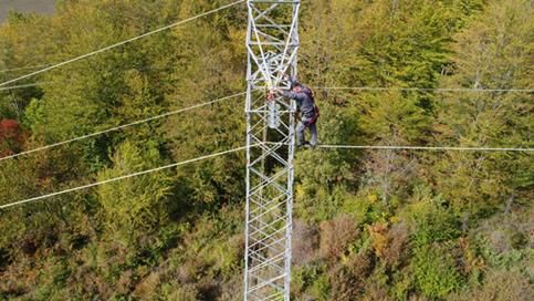
Ten Years Network Development Plan, period 2021-2030

                                                          Amax=105%

                                                          Vmin=95%

                                                           Imax=80%

                                                             Imin=0%

Figure 2.   Operating regimes with high loading in 2020
            - voltage profile and loading of lines

                                                                9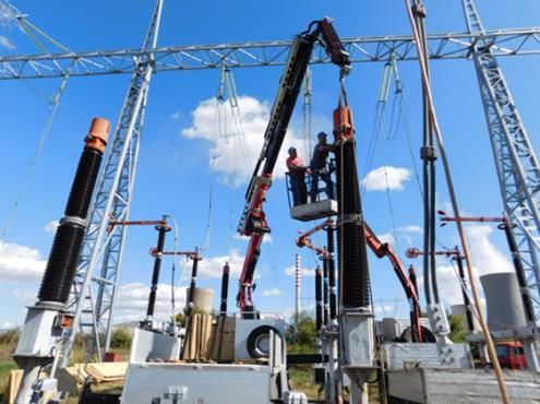
Ten Years Network Development Plan, period 2021-2030

Table 3.        Maximum values of the short-circuit currents in the transmission grid in 2020

                   U    3-СКВ   1-СКВ                       U    3-СКВ   1-СКВ
    Јазел                                     Јазел
                 [kV]    [kA]    [kA]                     [kV]    [kA]    [kA]

 BITOLA 2        400    17.5    15.1       BUCIM          110     8.7     6.9
 DUBROVO         400    17.3    14.1       TEARCE         110     8.7     8.3
 SK 4            400    14.5    13.3       VELES 2        110     8.7     8.5
 STIP            400    14.1    11.9       B.GNEOTINO     110     8.4     7.0
 SK 1            400    13.6    12.3       KUMANOVO 1     110     8.4     8.9
 SK 4            110    29.5    32.9       TOPILNICA      110     8.3     8.1
 SK 1            110    28.4    31.7       VELEC C        110     8.2     8.0
 ZLZ-SVR         110    25.7    26.0       O.POLE         110     8.1     6.5
 DUBROVO         110    23.6    28.1       POLOG          110     7.8     7.8
 TETO-EC         110    22.9    27.8       KUMANOVO 2     110     7.8     7.8
 SK 2            110    22.0    20.9       RAFINERIJA     110     7.8     6.9
 ZLZ-JUG         110    22.0    20.5       ZGROPOLCI      110     7.6     6.2
 BITOLA 2        110    21.8    26.8       SV.PETKA       110     7.5     7.3
 V.GLAVINOV      110    21.1    19.9       TETOVO 1       110     7.5     8.0
 DRACEVO         110    20.2    17.1       TETOVO 2       110     7.3     7.5
 TPP NEGOTINO    110    20.1    20.5       KOZJAK         110     6.9     7.2
 JUG NOVA        110    17.5    15.4       RADOVIS        110     6.8     6.1
 USJE            110    17.2    15.0       SAMOKOV        110     6.4     6.1
 SUVODOL-1       110    15.9    13.6       NEOKAZI        110     6.1     6.1
 BITOLA 1        110    15.8    14.4       KICEVO         110     6.1     5.1
 STIP 1          110    15.2    17.8       PRILEP 1       110     6.0     5.8
 G.BABA          110    15.1    13.6       PROBISTIP      110     5.7     5.7
 FENI            110    15.0    13.6       PRILEP 2       110     5.6     5.3
 KAVADARCI       110    14.3    13.0       SOPOTNICA      110     5.5     4.2
 TIKVES          110    14.1    13.4       SPILJE         110     5.3     5.7
 BITOLA 4        110    13.6    12.7       VALANDOVO      110     5.3     6.2
 SK 3            110    13.6    13.3       KRATOVO        110     5.1     4.3
 NEGOTINO        110    12.9    11.1       RESEN          110     5.0     4.7
 AERODROM        110    12.7    10.8       PRILEP 3       110     4.9     4.5
 ISTOK           110    12.5     9.8       STRUMICA 1     110     4.8     5.5
 ZAPAD           110    12.5    12.1       STRUMICA 2     110     4.8     5.4
 KAVADARCI 2     110    12.2    10.5       KOCANI         110     4.6     4.6
 G.PETROV        110    12.1    10.6       GLOBOCICA      110     4.5     4.8
 BITOLA 3        110    11.8    10.2       VEC BOGDANCI   110     3.8     5.6
 PETROVEC        110    11.4     9.8       M.KAMENICA     110     3.5     3.2
 STIP 2          110    11.3    10.4       BEROVO         110     3.5     2.9
 VRUTOK          110    11.0    12.6       OHRID 2        110     3.4     3.7
 KOZLE           110    10.8     9.8       STRUGA         110     3.4     3.6
 MILADINOVCI     110    10.1     7.1       OHRID 1        110     3.4     3.8
 JUGOHROM        110     9.8    10.1       DELCEVO        110     3.2     2.9
 GOSTIVAR        110     9.4     9.3       GEVGELIJA      110     3.1     3.5
 OSLOMEJ         110     8.9     9.7       SUSICA         110     3.1     2.8
 VELES           110     8.9     8.8       K.PALANKA      110     3.0     2.5
 BUNARGIK        110     8.8     8.0

                                                                                                10
Ten Years Network Development Plan, period 2021-2030
PROJECTS COMPLETED IN 2020
In 2020, MEPSO faced the challenge by the COVID-19 pandemic. MEPSO came to a
crossroads between providing secure, reliable, and stable (secure) operation of the
transmission grid and constant realization of the capital investment projects and studies.
A great number of the projects were successfully conducted according to the expected
dynamic. However, the pandemic with the COVID-19 virus was a reason for prolonging the
realization period for some projects and studies, but without financial implications.
3.1. RECONSTRUCTION AND REVITALIZATION OF TRANSMISSION LINES
Following the plan for reconstruction and revitalization of transmission lines, the SS Shtip -
SS Probishtip transmission line with a length of 25.2 km was renovated in 2020. The project
was financed by EBRD’s loan (44114) and MEPSO’s funds.
3.2. RECONSTRUCTION AND REVITALIZATION OF SUBSTATIONS
The reconstruction and revitalization of the equipment in the substations in 2020 runs
smoothly and according to the planned work dynamics.
With the revitalization of the 110 kV switchyard in SS Dubrovo included replacement of the
old primary and secondary equipment, which was in function since 1977. This complex
project covered replacement of primary equipment (circuit breakers, disconnectors, and
current and voltage measurement transformers), as well as the revitalization of the
secondary equipment on 400 kV and 110 kV voltage level that includes delivery and
installation of relay protection systems, for remote supervision and control, systems for
AC/DC supplies and complete revitalization of the electricity measuring system.
In SS Valandovo and the substation within TPP Oslomej was replaced part of the high-voltage
equipment (circuit breakers, disconnectors, and metering transformers) and secondary
equipment.
In SS Prilep was replaced part of the high-voltage equipment (circuit-breakers,
disconnectors, and metering transformers) and secondary equipment.
The relay protection was replaced in the substations connected to the power plants: HPP
Tikvesh, HPP Vrutok, HPP Globochica, and HPP Shpilje.
As part of the project for revitalization of the primary equipment in part of the 400 kV
substation owned by MEPSO, in SS Bitola 2 was obtained new 400/110 kV power transformer
with automatic voltage control, with a nominal power of 300 MVA. The installation of this
new transformer increases the reliability of the substation, reduces power losses in the
transmission network, and lowers the costs for maintenance of the installed transformers in
SS Bitola 2.
3.3. PROJECTS FOR POWER SYSTEM MODERNIZATION
The Wide Area Monitoring System (WAMS) enables prompt detection of deviation from the
operational safety margins. WAMS is based on real-time phasor and current measurement
units, simultaneously using GPS synchronization.
With this project was established a system for assessment of precise information about
possible violations in the synchronously connected power system in real-time, and it will
enable the undertaking of proper corrective measures.
The realization of the project included determination of optimal locations for installation of
WAMS in order to deal with the stability problems of the power system via high-quality
supervision in real-time, WAMS installation with the necessary technical specifications, and
11Ten Years Network Development Plan, period 2021-2030
installation of the central unit in the National Dispatch Centre with dynamic system stability
control.
Figure 3. Fieldwork activities – substations and transmission lines
12Ten Years Network Development Plan, period 2021-2030
4. NEW INTERCONNECTONS TOWARDS THE NEIGHBORS
Interconnections bring benefits that reflect incomes like an increase of the cross-border
transmission capacity, boost in transits among the power systems from the region, decrease
of electricity losses, and electricity price balancing in the region. Besides the above-
mentioned fundamental benefits, there are other positive impacts regarding the social
values such as improved supply reliability, cut investments in generation facilities for
national system reserves, regional dispatching and reduced generation costs, as well as
generation of reactive power.
4.1. 400 KV INTERCONNECTION MK – AL
The realization of Corridor 8 is of great significance for our country. Regarded from the
geostrategic aspect, Corridor 8 is an integral part of one much larger and exclusively
significant project that includes exploitation of energetic sources from the Caspian region
and Central Asia. Therefore, a “Joint Statement for Energy Infrastructure Cooperation” was
signed on 13 April 2005 in Sofia by the Ministers from the energy sector of Albania, Bulgaria,
Italy, and North Macedonia, whose aim is to support the implementation of the energetic
infrastructural projects according to the EU legislation including the projects of Trans-
European Networks (TEN) and in the European-Mediterranean Energetic Ring.
From power engineering aspect the 400 kV interconnecting overhead transmission line Bitola
(MK) – Elbasan (AL) represents the last part from the realization of Corridor 8 (East-West)
for transmission of electric power between Bulgaria, North Macedonia, Albania, and Italy.
The part between BG and MK is completed, and the realization of the submarine cable
between IT and ME is in progress by now completed the first phase and installed capacity of
600 MW from foreseen 1200 MW. The 400 kV interconnection between AL and ME and AL and
KS are already in service.
Regarding the development of the Macedonian transmission grid, the problems that exist in
the south-western part of the transmission grid will be solved with the construction of a new
400/110 kV transformer substation in the Ohrid-Struga region with in/out connections to the
new 400 kV transmission line Bitola (MK) –Elbasan (AL).
400 kV transmission line MK-AL has regional significance and PECI status (Project of Energy
Community Interest), by a decision made by the Energy Community Ministerial Council from
14 October 2016.
The project is presented in Table 12, positions 1 and 2.
4.1.1. Technical Specifications
The project for the 400 kV interconnection MK-AL on the Macedonian territory is comprised
of:
- 400 kV transmission line from SS Bitola 2 to the Macedonian/Albanian border,
- 400/110 kV SS Ohrid, and
- 400 kV transmission bay in SS Bitola 2
Technical specification of the Macedonian part of the 400 kV transmission line Bitola (MK) –
Elbasan (AL) are given in Table 4.
13Ten Years Network Development Plan, period 2021-2030
Table 4. Technical specification of 400 kV TL SS Bitola – MK/AL border
Nominal voltage 400 kV
Length on Macedonian territory 97,409 km
Type of towers Steel-lattice tower, type “Y”
Total number of towers 269
Type of conductors ACSR 490/65 mm2, 2 conductors by phase
Type of ground wires One with AWG 19/9, 126.1 mm2, other with OPGW
Altitude 550 – 1200 mnv
Middle span 358,26 m
Figure 4. 400 kV interconnection TL SS Bitola 2 – Macedonian-Albanian border
and SS 400/110 kV Ohrid route
The 400/110 kV SS Ohrid is planned to be built near the village of Mesheishta. Power
transformer is planned to be installed in the substation with apparent power of 300 MVA,
and will be comprised of:
Table 4. Structure of 400 kV and 110 kV switchyard 400/110 kV SS Ohrid
400 kV facility: 110 kV facility:
1. Coupling bay 1. Coupling bay
2. TL bay “SS Elbasan 3” 2. TL bay “SS Struga”
3. SS bay 1 3. Auxiliary TL bay
4. Auxiliary SS bay 4. SS bay 1
5. Auxiliary TL bay 5. TL bay “SS Ohrid 1”
6. TL bay “SS Bitola 2” 6. TL bay “SS Ohrid 2”
7. TL bay “SS Resen”
8. Auxiliary TL bay
9. Auxiliary SS bay
10. Auxiliary load
14Ten Years Network Development Plan, period 2021-2030
4.1.2. Financial and Economic Parameters
Feasibility Study for 400 kV Interconnection MK-AL
The financial and economical parameters by the Macedonian part of the project according
to the Feasibility Study 400 kV interconnection Bitola-Elbasan completed in January 2013,
are shown in the following Table:
Table 5. Financial parameters of the 400 kV interconnection Bitola (MK) – Elbasan (AL)
Main indicators: MK
Required investment 43.500.000 EUR
Net present value (NPV) 6.300.000 EUR
Simple Payback period 15 years
Benefit Cost Ratio 2.6
Intern Rate of Return (IRR) 12,5 %
The estimated investment value for the Macedonian part of the project, according to the
Feasibility Study for 400 kV interconnection Bitola-Elbasan is the following:
Table 6. Estimated investment for components of the 400 kV interconnection MK – AL
1. 400 kV transmission line from SS Bitola 2 - MK/AL border 28,3 MEUR
2. 400/110 kV SS Ohrid 14,3 MEUR
3. 400 kV transmission line in SS Bitola 2 0,85 MEUR
TOTAL 43,5 MEUR
Provided funds for implementation of the Macedonian part of the 400 kV interconnection
Bitola-Elbasan
For the realization of the project, the Western Balkans Investment Framework (WBIF)
approved the following three grants:
- WBIF regional grant for technical support (WBIF4bis-REG-ENE-01) – 803.000 euros
- The following studies were prepared as part of this regional grant:
- Feasibility Study for 400 kV interconnection Elbasan (AL) – Bitola (MK)
- Studies on Environmental Impact Assessment of the 400 kV TL SS Bitola 2 –
Macedonian/Albanian border
- Studies on Environmental Impact Assessment of the 400 kV TL SS Elbasan 3 –
Albanian/Macedonian border
- WBIF grant for technical support (WB9-MKD-ENE-01) – 900.000 euros
- Complete project documentation was prepared within the framework of this grant:
- 400 kV transmission line from SS Bitola 2 – Macedonian/Albanian border
- 400/110 kV SS Ohrid
- 400 kV transmission bay in SS Bitola 2
15Ten Years Network Development Plan, period 2021-2030
- 110 kV connection transmission lines to 400/110 kV SS Ohrid
- WBIF investment grant (WB-IG00-MKD-ENE-01) – 12.000.000 euros
In December 2015 was signed a financial agreement with the European Bank for
Reconstruction and Development (EBRD) for a loan for the project with the following
parameters:
- Loan Agreement No. EBRD loan No.46274,
- Signed on date: 10 December 2015,
- Loan: 37.000.000 euros, and
- Repayment period of 15 years including a grace period of 3,5 years
The total costs as per the signed agreements, the structure of the financing resources, and
the time dynamics for realization for the period 2021-2030 are presented in Table 12,
position 1 and position 2.
The allocation of the costs for the realization of the project (as per the signed agreements,
excluding the feasibility studies, technical documentation, and consultant’s services)
according to the financing resources is as follows:
Table 7. Costs as per the contracts for construction for the 400 kV interconnection MK-AL
Summed
Loan Own funds Grant
values
Components (MEUR) (MEUR) (MEUR)
(MEUR)
400 kV interconnection line SS Bitola
14,59 9,59 0 5,00
2 – Macedonian/Albanian border
400/110 kV SS Ohrid and new 400kV
14,37 10,37 0 4,00
TL bay in SS Bitola 2
4.1.3. Project Implementation
Completed activities:
- Preparation of Feasibility Studies and Studies on environmental impact assessment (both
the Macedonian and Albanian part of the interconnection)
- Financed by Grant I by WBIF: 800.000 euros (650.000 euros for the Macedonian part of
the project)
- Final version: January 2013.
- Prepared by COWI (WBIF Consultant team).
- Decision on approval for the Study on environmental impact assessment
- Issued on 27 July 2015 by the Ministry of Environment and Physical Planning after the
competition of the procedure for assessment of the project impact on the environment.
- Research on vulnerable group fauna (birds and bets) across the corridor from the
Macedonian part of the interconnection
- One-year research in the period from 2016-2017 was conducted on demand by the
Ministry of Environment and Physical Planning.
- The research was conducted by the Civil Engineering Institute Macedonia (GIM) –Skopje
- Preparation of complete project documentation
- Financed by Grant II by WBIF, awarded in 2013: 899.098 euros
16Ten Years Network Development Plan, period 2021-2030
- It is prepared by the Consultant/Contractor GEING-Skopje, which has begun with the
preparation of the documentation in 2016.
- The tender was opened in August 2019
- Construction Contracts were signed:
o 400 kV transmission line Bitola – MK/AL border: Energoinvest, Sarajevo,
o 400/110 kV SS Ohrid: Končar, Zagreb.
Further steps:
- Finalization of the transformer substation and transmission line design,
- Marking of the transformer substation and transmission line location,
- Geomechanical researches,
- Construction works, access way, equipment procurement, and supply of a part of the
equipment.
Due to the COVID -19 pandemic, the project was prolonged for a year, and it is expected to
be completed by 2023.
17Ten Years Network Development Plan, period 2021-2030
5. MEASURES AND INVESTMENTS IN THE PERIOD 2021-2030
Generally, the transmission grid operates satisfyingly from the aspect of safety, reliability
and, security of supply.
Potential faults in the operational security of the grid in the short-term will be solved with
re-dispatching of the production and/or with system unloading, by taking on some
undertakings on the grid and with completion of the already started projects, while in the
middle-term/long-term period such faults will be solved with the realization of new
projects.
5.1. NORTHERN REGION OF THE TRANSMISSION NETWORK
The calculation of the maximum short-circuit currents for the transmission grid in the short-
term period revealed that very high values of short-circuit currents may be expected at 110
kV busbars in SS Skopje 1 and SS Skopje 4 (over 90% from 40 kA).
In the medium-term and during a normal operating regime of the EPS, the value of the short-
circuit current at the 110 kV busbars exceeds the switching power of the installed
equipment.
Busbars shall be sectioned to reduce the short-circuit currents at the 110 kV busbars in SS
Skopje 1 and SS Skopje 4, sectioning of busbars shall be done. Those switchyards have a
double and auxiliary system of busbars (more complicated design) and considerable
flexibility in the system operation is possible, more precisely, every unit (transmission line,
transformer substation) may be connected to one of the two busbar systems. While
sectioning, the choice of units that will be connected to particular sections is important and
there are several ways how the sectioning may be done. Sectioning of 110 kV busbars in SS
Skopje 4 and SS Skopje 1 shall be performed in such a way that the single-phase and the
three-phase short-circuit currents after the sectioning have to be almost equal in two
sections, thus fulfilling the N-1 system security criterion.
Figure 5. Options for transmission network sectioning in Skopje region, planned topology in
the middle-term horizon
18Ten Years Network Development Plan, period 2021-2030
5.2. WESTERN REGION OF THE TRANSMISSION NETWORK
In the region of Polog, in the process of realization is the project for the construction of the
110 kV double-circuit transmission line, which spreads from HPP Vrutok to SS Tetovo 1, as
well as reconfiguration of the transmission network. In 2021, for completion and supervision
of the construction transmission line shall be undertaken civil engineering and electrical
engineering actions; Table 12, position 7.
To surpass ultimate design loads, which occur when there is an outage at the 110 kV TL
Vrutok – Tetovo 1, the Study on transmission grid development suggests connection of the
already existing 110 kV TL Vrutok – Skopje 1 via connection type line in/ line out in SS Tetovo
1. So additional reconfiguration in the Polog region will be made, and new connections will
be formed: HPP Vrutok –SS Tetovo 1 and SS Tetovo 1 – SS Skopje 1.This action is prolonged
for a year, and it is expected to be executed in the period from 2021-2025; Table 12, position
3.
present topology in southeast region present topology in southeast region
without power outages outage at 110 kV TL Resen – Bitola 4
New 400/110 kV SS Ohrid, in operation New 400/110 kV SS Ohrid in operation
without power outages outage at 110 kV TL Resen – Bitola 4
Figure 6. Benefits from 400/110 kV SS Ohrid regarding critical operating regimes
19Ten Years Network Development Plan, period 2021-2030
Regarding the quality of the voltages in the transmission grid and the security of the power
supply, of crucial importance is the construction of the 400/110 kV SS Ohrid, part of the
south-western region of the transmission grid. In line with expectations, this substation shall
be completed by 2023. Without its construction and active involvement of the power plants
in the power regulations, the south-western region is subject to possible voltage collapse
and loss in the power supply in the 110 kV network (N-1 criterion) (see Figure 6). Until the
400/110 kV SS Ohrid (see 4.1) is constructed, the power plants in the south-western region:
HPP Vrutok, HPP Globochica, and HPP Shpilje must actively participate in the regulation of
power and reactive power flows.
Calculations from the security analysis (N-1 criterion) in the Study on transmission grid
development indicate that in the western region when there is high hydrology (with the
maximum engagement of HPP Kozjak and HPP Sv.Petka, and high engagement of TPP
Oslomej), and regimes with single power outages, then critical loads appear in the following
110 kV transmission lines: SS Kichevo - TPP Oslomej (105 %), SS Gostivar – HPP Oslomej
(108%), SS Sopotnica – SS Bitola 1 (110%), HPP Kozjak – HPP Sv.Petka (from 100% to 105%)
and HPP Sv.Petka – SS Skopje 3 (from 100% to 105%). As a middle-term solution of the
overload problem in the western region is discerned the reconstruction/revitalization of the
whole 110 kV link Gostivar – Oslomej – Kichevo – Sopotnica – Bitola 1 via utilization of
conductors with higher transmission power (AAAC 324 mm2, 149 MVA). This
reconstruction/revitalization is planned to be carried out in the period from 2021-2024. The
110 kV link TPP Oslomej – Kichevo – Sopotnica – Bitola is built in 1960 and has ACSR 150/25
mm2, 93 MVA types of conductors; Table 12, position 13.
The solution of the problem with overload in the western region in a long-term period
foresees additional reconstruction/revitalization of the 110 kV connection SS Polog – HPP
Vrutok – HPP Shpilje – HPP Globochica – SS Struga with utilization of the conductors with
higher transmission capacity (AAAC 324 mm2, 149 MVA), and low sag-tension value of
conductors (AAAC). This reconstruction/revitalization is planned to be carried out after
2030, while the preparation of the technical documentation shall start from 2027. The 110
kV connection SS Polog – HPP Vrutok – HPP Shpilje – HPP Globochica - SS Struga is built in the
period 1964 -1970 and has ACSR 240/40 mm2, 121 MVA types of conductors; Table 12, position
15.
5.3. EASTERN REGION OF THE TRANSMISSION NETWORK
In the southeast region (Valandovo-Strumica), a great number of renewable energy sources
(RES) – wind farms and solar1 power plants are planned to be built. Their connection to the
transmission network causes overloads on the 110 kV transmission lines and low loadings in
operating regimes with outages (N-1 criterion). To achieve secure operational conditions of
the system, and therefore taking into account the announced connections of RES in the
southeast region, in the middle-term period, as a variant is suggested construction of a 110
kV double-circular transmission lines with greater transmission capacity and low sag-tension
value of conductors (AAAC) during the reconstruction of the existing 110 kV transmission
lines: SS Dubrovo – SS Valandovo and SS Valandovo – SS Strumica 2 – SS Strumica 1. Another
variant is improvement of the network with new 400/110 kV transformer substation in the
region, which opens up the opportunity for future construction of a second 400 kV
1
Solar power plants (SPP) use different generation technology. Currently, most present are farms
with photovoltaic panels, but there are also photovoltaic panels used on roofs or façade. For large
capacities, there are reflecting surfaces and generation through condensation. In the text, for all
types of solar power plants, in general, is used the abbreviation “SPP” while for precise connections
of users is mentioned the used technology; up to the present, all users plan to build photovoltaic solar
power plants (PVPP).
20Ten Years Network Development Plan, period 2021-2030
interconnection towards Bulgaria. The optimal solution shall be defined in Study 8.6. This
project is presented in Table 12, position 14.
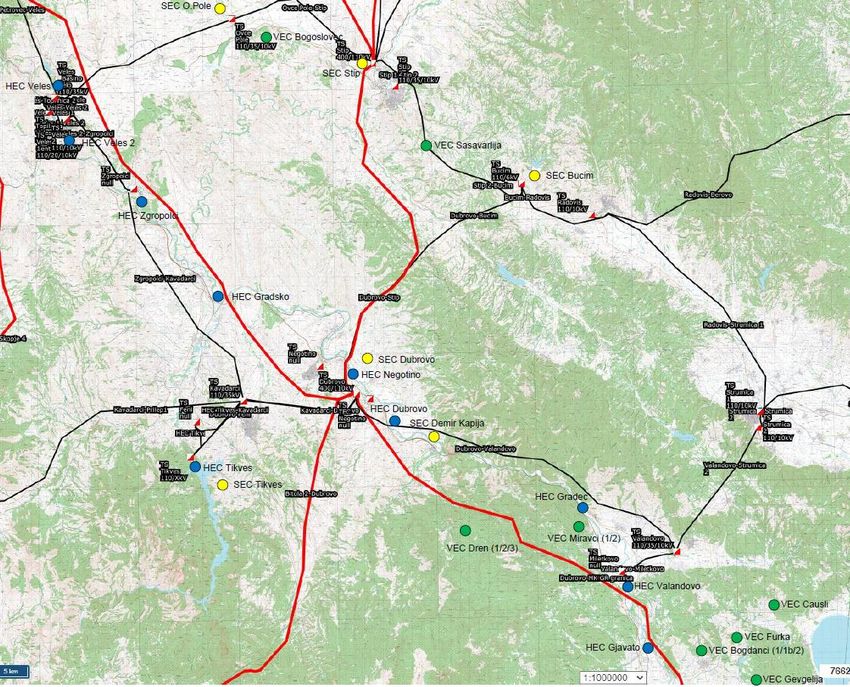
Figure 7. New power plants in the southeast region
(potential capacity as per “green” scenario: PVPP 388 MW, VPP 536 MW, HPP 341 MW)
To overcome low voltages condition in the eastern region in the long-term period is foreseen
installation of compensational device (reactive power source) in the 110 kV SS Kochani with
minimal power of 25 MVAr; Table 12, position 26.
Due to the increase of the power load in the middle-term and long-term period in the
Kumanovo region, and unfulfillment of the system security N-1 criterion, a new SS 400/110
kV Kumanovo is necessary to be built, including decoupling of the 110 kV transmission lines,
and redistribution of loads among 110 kV SS Kumanovo 1, 110 kV SS Kumanovo 2 and the new
110 kV SS Kumanovo 3; Table 12, position 4.
21Ten Years Network Development Plan, period 2021-2030
6. RECONSTRUCTION AND REVITALIZATION WITHIN THE TRANSMISSION NETWORK
The aging process of the transmission facilities and equipment has a significant effect on the
system operation and planning of the transmission grid. Unreliable and older switchyards
may endanger the reliability and safety of the whole power system. For MEPSO, it is
important to make a choice of optimal moment for revitalization or replacement of the
equipment, in order to preserve a satisfactory level of system reliability and security.
Transmission facilities and equipment (overhead transmission lines, cables, transformer
substations, protection systems, systems for control and management, measurement
systems, telecommunication installations, etc.) are aging during their operation. Every
transmission facility and equipment has its life expectancy. The transmission equipment is
expected to work according to the declared specifications during their life expectancy,
without a major number of faults and problems. The life expectancy for the same type of
equipment may be changed over a broad span due to different factors of influence like
climate conditions, operational conditions, and specifications. During the aging process, the
equipment gradually loses its characteristics and so the number of defects and their duration
increases. Providing satisfactory and periodical maintenance the transmission equipment
could reliably work in accordance with the declared specifications until that is possible
because of its age.
The reconstruction and revitalization of the existing equipment, in the ten-year
development plan, are expected to give the following positive effects:
- Strengthened operational security of the switchyards;
- Decreased amortization rate of the equipment installed at the transmission bays in
the transformer substations;
- Significantly reduced number of outages in the transmission lines, thus decreased
no-voltage condition towards the consumers;
- Increased level of a consistent supply of electric power to the consumers;
- Lower costs for maintenance and elimination management problems with the old
transmission lines;
- Improvement of the quality of the electricity at power system level
- Improvement of the employees and environment safety
6.1. RECONSTRUCTION AND REVITALIZATION OF TRANSMISSION LINES
The Macedonian transmission grid is intensively built during the 1960s and 1970s. One of the
main challenges of MEPSO for the upcoming years is reconstruction of the obsolete 110 kV
transmission lines. Those transmission lines that are estimated to have impaired operational
parameters will be reconstructed with an aim to maintain the operational reliability and
security of the power system.
6.1.1. RECONSTRUCTION OF TRANSMISSION LINES
The reconstruction of the 110 kV transmission lines has begun and is financed by a loan from
EBRP (44114) as component 4 given in the following Table:
22Ten Years Network Development Plan, period 2021-2030
Table 9. Reconstruction of the 110 kV transmission lines in the period 2021-2030
(Table 10, positions from 8 to 13)
Transmission line Length Year of Activities in
(km) construction 2020
SS Bunardjik – SS Miladinovci 1 17 1971 Change of route
21 1960 In designing
SS Veles – SS Ovche Pole and
construction
phase
17.9 1960 In designing
SS Ovche Pole – SS Shtip and
construction
phase
33.7 1963 In designing
SS Bitola 1 – SS Prilep 1 and
construction
phase
37 1953 In designing
SS Skopje 4 – SS Petrovec – SS Veles and
construction
phase
SS Gostivar (Bukovikj) – TPP Oslomej - 100 1960 In designing
Kichevo - Sopotnica - Bitola 1 (length ≈ 100 phase
km AAAC)
For the reconstruction of the 110 kV transmission lines SS Veles – SS Ovche Pole, SS Ovche
Pole – SS Shtip, SS Bitola 1 – SS Prilep, and SS Skopje 4 – SS Petrovec – SS Veles (Table 12,
positions for 9 to 12), in 2021 the following activities are foreseen: expropriation, audit of
the project, civil engineering works, electrical engineering activities, and supervision of the
complete work. For the reconstruction of the transmission line SS Bunardjik – SS Miladinovci,
during 2021, besides the above-mentioned activities, also it is foreseen preparation
Environmental Impact Assessment.
According to the measures that have to be undertaken in the following 10-years period, in
order to ensure a stable electric power supply without overloads and low voltages in the
transmission system, precisely to provide qualitative electric power transmission, the
following 110 V transmission lines are planned to be reconstructed/revitalized:
Table 8. Reconstruction/revitalization of the 110 kV transmission lines in the period 2021-
2030 (Table 10, positions 6 and from 13 to 15)
Transmission line Length Year of Intervention
(km) construction
2х110kV TL section
11 1970
Vapila – SS Ohrid 1
SS Gostivar (Bukovikj) – 1958/1978/200
TPP Oslomej 1
TPP Oslomej – SS Kichevo 15 1960 New conductor AAAC
SS Kichevo – SS Sopotnica 33,3 1960
SS Sopotnica – SS Bitola 1 30,7 1960
SS Durbinovo –SS Valandovo 39,3 1971 Double-circuit TL with
SS Valandovo – SS Strumica 2 – conductor AAAC
~ 18 1971
SS Strimica 1 option 400/110 kV SS
23Ten Years Network Development Plan, period 2021-2030
HPP Vrutok – SS Polog 9 2010
HPP Vrutok – HPP Shpilje 15,6 1964
New conductor AAAC
HPP Shpiljе – HPP Globochica 13,5 1964
HPP Globochica – SS Struga 32 1970
In 2021, for the reconstruction of the 2x110 kV transmission line, section Vapila – Ohrid 1,
tender for preparation of project documentation will be organized. For the 110 kV TL
Gostivar – Bitola 1, a designer is selected who is already preparing the project. During the
current year will be prepared tender for Contractor.
REVITALIZATION OF TRANSMISSION LINE
The plans for maintenance of the transmission grid include continuous revitalization of the
existing transmission lines of MEPSO via replacement of the fittings and suspension set,
earthing wires, and replacement of the existing conductors with a new type of wires with
better specifications compared to the existing; Table 12, position 5.
Figure 8. Interventions on transmission lines
6.2. Reconstruction and Revitalization of Substations
The reconstruction and revitalization of the equipment in the substations comes because of
real technical needs identified from different points of view:
- Equipment older than 30 years and inability to procure spare components
- Difficulties in the maintenance of the equipment
- Bad operational parameters of the equipment that is in function
- Obstacles to manage the equipment
- Risk to the employees and environment during manipulation with the equipment.
Analysis had been made for the condition of the 400/110 kV power transformers based on
the results from the “periodical surveys”, operation supervision, and laboratory testing.
24Ten Years Network Development Plan, period 2021-2030
Based on these analyses, in the long-term period, replacement by one power transformer in
SS Skopje 4- SS Dubrovo is foreseen. These replacements of power transformers are given in
Table 12, positions 21 and 22.
The procedure for replacement of the old and unreliable 400 kV and 110 kV primary
equipment with average age over 30 years (circuit breakers, disconnectors, metering
transformers, and surge/lightning arrestors), and replacement of the secondary equipment
(relay protection, remote control, and control systems, supply, electric energy
measurement) continues with an aim to increase the stability and reliability of the
substations and the power system.
Due to the age of the buildings (control buildings, premises, objects, fences, etc.) within
the substations, constant actions are being undertaken for their repair. The repair of the
control buildings, premises, objects is carried out with an aim to improve the energy
efficiency as well.
The reconstruction and revitalization of the substations are carried out through more
projects/packages, described below.
6.2.1. Revitalization of High-voltage Equipment
The plan for revitalization of part of the high-voltage equipment – disconnectors, in several
substations results from the necessity to lower costs for maintenance, and to increase the
reliability and availability of system elements. The existing disconnectors are old (average
age is 35 years), with often defects because of which the maintenance costs are high.
This project will cover the replacement of disconnectors in the following substations:
Table 9. Revitalization of disconnectors in 13 substations (Table 10, position 17)
Transformer substation Number of bays Number of disconnectors
Bitola 1 8 23
Bitola 3 3 5
Bitola 4 4 6
Buchim 5 13
Radovish 5 8
Strumica 2 3 5
Skopje 3 10 22
Gjorche Petrov 5 6
Kriva Palanka 5 7
Makedonska Kamenica 3 5
Kumanovo 2 5 7
Kochani 5 7
Samokov 4 6
Total 65 120
6.2.2. Reconstruction of Switchyard Kratovo
The reconstruction of the switchyard in Kratovo includes realization of 3 transmission bays,
new 110 kV busbar-system and reconstruction of the secondary circuits using the most
modern digital technology; Table 12, position 18.
25Ten Years Network Development Plan, period 2021-2030
6.2.3. Revitalization of the 400/110 kV Substations
(SS Skopje 4, SS Bitola 2, SS Dubrovo)
Within these substations will be replaced part of the high-voltage equipment and part of the
secondary equipment; Table 12, positions 19-25. Whereas in SS Skopje 4 will be replaced the
supports and foundations of the 400 kV facility.
According to the new contract signed by MEPSO, in the following three years is foreseen
reconstruction of the high-voltage equipment in SS Bitola 2, precisely the 400 kV and 110 kV
disconnectors and metering transformers, as well as reconstruction of the secondary
equipment; Table 6. position 25. As part of this reconstruction, withinin the 400 kV
switchyard will be procured and installed 25 disconnectors in all 9 bays, and 14 post
insulators in 8 bays, while within the 110 kV switchyard will be procured and installed 42
disconnectors in all of the 14 bays and 75 metering transformers in 13 bays.
In SS Dubrovo in the past period, the 110 kV switchyard was completely reconstructed
(replacement of circuit-breakers, disconnectors, metering transformers, relay, protection,
and control system-SCADA), and the 400 kV switchyard was partially reconstructed replacing
the relay protection and control. Since the circuit-breakers and metering transformers had
been previously replaced, in the upcoming period the disconnectors in the 400 kV switchyard
will be replaced.
The revitalization involves replacement of the 400 kV disconnectors in all bays (22 sets),
construction of a new 110 kV bay (C2) for the auxiliary load (with 110 kV metering
transformers with high capacity), and partial reconstruction of 6 kV switchyard (replacement
of circuit-breakers, metering transformers, relay protection, and control system – SCADA).
6.2.4. Revitalization of SS Veles and SS Kavadarci 1
This project foresees replacement of part of the high-voltage equipment and secondary
equipment in SS Veles and SS Kavadarci 1, and installation of the already procured equipment
for DC supply and AC/DC supply; Table 12, position 27.
26Ten Years Network Development Plan, period 2021-2030
Figure 9. Installation of equipment in substations
6.3. REVITALIZATION/RECONSTRUCTION OF CONTROL SYSTEMS IN SUBSTATIONS
6.3.1. Revitalization and Modernization of the Control System in SS Samokov
Installation of a system for control and supervision of SS Samokov based on SCADA software
and Bay Control Unit (BCU) devices. The reconstruction is planned to cover designing and
realization of electrical installation works, testing and commissioning, preparation of main
design and set of as-built records; Table 6, position 28.
6.3.2. Revitalization and Modernization of the Control System in SS Strumica1
Installation of a system for control and supervision including designing and realization of
electrical installation works, testing, and commissioning, preparation of design. Besides the
increase of availability and reliability of the SS, the acquired data from the SS will be
implemented in SCADA/EMS system in NDC; Table 6, position 29.
6.3.3. Revitalization and Modernization of the Control System in SS Sushica
Installation of a system for control and supervision including designing and realization of
electrical installation works, testing, and commissioning, preparation of design. Regarding
that SS Sushica is interconnected with Bulgaria, it is very important that all necessary
measurements, statuses, alarms are available in SCADA/EMS system in NDC; Table 6, position
30.
27Ten Years Network Development Plan, period 2021-2030
Figure 10. National Dispatch Center
28Ten Years Network Development Plan, period 2021-2030
7. MODERNIZATION OF THE POWER SYSTEM
Modernization, digitalization, and cyber security in the power system are significant part of
the operation of MEPSO. For that purpose, in this year’s plan for development of the power
system MEPSO introduces five new projects: procurement and installation of new SCADA/EMS
system, Data Room, ENTSO-E Electronic Highway in NDC and BDC, smart maintenance and
management of the equipment whose realization starts in 2021. In mid-term is planned
procurement of voltage profile compensator.
TELECOMMUNICATION EQUIPMENT AND REMOTE MONITORING OF THE SUBSTATIONS
MEPSO has built telecommunication infrastructure for telecommunication connection of the
power plants. This infrastructure is comprised of optical fiber network integrated into the
ground wires (OPGW) of the line and the telecommunication equipment. The optical network
integrated into the ground wires of the transmission lines is depicted in the following Figure:
Врање 4 Србија Могила
Урошевац 2 Vranje 4
Ferizaj 2 Serbia Mogila
Косово Скакавица
Skakavica
Kosovo Железара
Куманово 2
Kumanovo 2 Кратово
Kratovo
К.Паланка
Скопје 1
Zhelezara
Скопје 5
Куманово 1
K.Palanka
М.Каменица
Бугарија
Теарце Skopje 1 Skopje 5
Тетово 1
Tetovo 1
Tearce Ѓ.Петров
G.Petrov
ТЕ ТО
Kumanovo 1
Рафинерија
Пробиштип
Probishtip
M.Kamenica
Bulgaria
Тетово 2 Југохром Rafinerija
Jugohrom Кочани Делчево
Tetovo 2 Бунарџик
Скопје 3 Bunardzik Kochani Delchevo
Skopje 3 О.Поле
Св.Петка Скопје 4 Петровец
Полог Petrovec O.Pole
Skopje 4
Polog Sv.Petka Југ Топилница Велес Штип
Jug Topilnica Штип 1 Shtip
Козјак Veles
Shtip 1
НДЦ МЕПСО Штип 2
Вруток Гостивар
Kozjak Велес 2
NDC MEPSO Shtip 2
Vrutok Gostivar Veles 2 Бучим Берово
Самоков Централна Buchim Berovo
Samokov ЕСМ
Centralna
ESM Згрополци
Zgropolci Радовиш
Осломеј Неготино Radovish
Negotino
Oslomej Кавадарци Дуброво
Кичeво Струмица 1 Сушица
Шпиље Kichevo
Kavadarci Dubrovo Strumica 1 Sushica
Shpilje Прилеп 3 Градска Неготино
Prilep 3 Gradska Струмица 2
Negotino
Глобочица Прилеп 2
Фени
Strumica 2 Петрич
Prilep 2 Вaландово
Globochica Тиквеш Feni Petrich
Сопотница Прилеп 1 Valandovo
Prilep 1 Tikvesh
Sopotnica
Струга
Struga Гевгелија
Охрид 1 Богданци
Ohrid 1 Битола 2 Gevgelija
Bogdanci
Битола 1 Bitola 2
Охрид 2 Bitola 1 Суводол
Грција
Ohrid 2
Ресен Битола 4
Suvodol
Битола Солун
Resen Bitola 4 Битола 3
Bitola 3 Б.Гнеотино
Bitola
Greece Thessaloniki
B.Gneotino
ХЕЦ (HPP) 400 kV ДВ (OHL)
ТС 400/110 kV
Албанија ВЕЦ (WPP) 110 kV ДВ (OHL)
Овчарани ТЕЦ (TPP) OPGW ТС (SS) 110/x kV
Albania Meliti ТЕТО (TETO)
OPGW
до крај на 2020
(till the end of 2020)
2020 година (year)
Figure 11. OPGW across the transmission lines of the transmission network
This project will include procurement and installation of telecommunication equipment,
construction of a new network for data transmission from the supervision and control system,
electric power metering, relay protection, LAN and WLAN network, telephone lines; Table
12, position 31.
Telecommunication equipment is a base for achieving “real-time” data for SCADA/EMS2, as
well as for interconnection with the neighbors and connecting the data from all locations of
2
Supervisory control and data acquisition
29You can also read