Limitations of the PlayStation 3 for High Performance Cluster Computing
←
→
Page content transcription
If your browser does not render page correctly, please read the page content below
Limitations of the PlayStation 3 for High
            Performance Cluster Computing

                Alfredo Buttari1 , Jack Dongarra12 , Jakub Kurzak1
1
    Department of Computer Science, University Tennessee, Knoxville, Tennessee 37996
2
    Computer Science and Mathematics Division, Oak Ridge National Laboratory, Oak
                              Ridge, Tennessee, 37831

1     Introduction

Power consumption, heat dissipation and other physical limitations are push-
ing the microprocessor industry towards multicore design patterns. Most of the
processor manufacturers, such as Intel and AMD, are following more conven-
tional approaches, which consist of homogeneous, symmetric multicores where
execution units are replicated on the same dime; multiple execution units share
some cache level (generally L2 and L3) and the bus to memory. Other manufac-
turers proposed still homogeneous approaches but with a stronger emphasis on
parallelism and hyperthreading. This is, for example, the case of Sun with the
UltraSPARC T1 (known as “Niagara”). The UltraSPARC T1 [25,24] can have
up to eight homogeneous cores each of which is four-way hyperthreaded which
delivers a maximum parallelism degree of thirty-two. The Niagara processor is
mostly developed for web servers and database applications since it provides
high computational power for integer operations, which are used considerably in
pointer arithmetics and string processing. Yet other chip manufacturers started
exploring heterogeneous designs where cores have different architectural features.
One such example is the Cell Broadband Engine [22,17,19,18] developed by STI,
a consortium formed by Sony, Toshiba and IBM. The Cell BE has outstanding
floating-point computational power, which makes it a considerable candidate for
high performance computing systems. IBM shipped the first Cell-based system,
the BladeCenter QS20, on September 12th 2006. This blade is equipped with
two Cell processors with a 512 MB memory each and connected in a NUMA
configuration; the external connectivity is achieved through a Gigabit and an
Infiniband network interface. The BladeCenter QS20 has impressive computa-
tional power that, coupled with its high speed network interfaces, makes it a good
candidate for high performance cluster computing. At almost the same period
(November 11th), Sony released the PlayStation 3 (PS3) gaming console. Even
if this console is not meant for high performance computing, it is still equipped
with a (stripped down) Cell processor and its price (∼ $600) definitely makes
it an attractive solution for building a Cell-based cluster. This document aims
at evaluating the performance and the limitations of the PS3 platform for high
performance cluster computing.
2 The Cell processor
2.1 Architecture characteristics
The Cell Broadband Engine is a multicore processor with nine computational
units connected by a high-bandwidth bus. Figure 1 shows the Cell’s architecture.
Fig. 1. Architecture of the CELL processor.
The most important components of the Cell’s architecture are:
PowerPC Processor Element (PPE). The PPE is the main core and it con-
tains a PowerPC 64-bit processor. It is mostly meant for controlling and co-
ordinating the SPEs even though it is capable of considerable floating point
performance thanks to the Altivec SIMD unit.Synergistic Processor Elements (SPEs). The Cell processor is equipped
with eight SPEs, which are SIMD execution units. Each of them contains a
RISC core which supports a special SIMD instruction set, a 256 KB software
controlled Local Store (LS) and a large register file made up of 128 128-bit
registers. Connectivity with the EIB (see below) is provided by the Memory
Flow Controller (MFC). The MFC contains a DMA controller that supports
DMA transfers. Programs running on the SPE, the PPE, or another SPE,
use the MFC’s DMA transfers to move instructions and data between the
SPU’s LS and main storage. Figure 2 shows the architecture of the SPEs.
The SPEs can only execute code residing in the local store and only operate
Fig. 2. Architecture of the SPE units.
on data residing in the local store. To the SPE, the local store represents
a flat, 18-bit address space. Code and data can be moved between main
memory and the local store through the internal bus (see next section) using
Direct Memory Access (DMA) capabilities of the Memory Flow Controller.
In principle, the SPEs constitute a small, distributed memory system on a
chip, where data motion is managed with explicit messaging. The DMA fa-
cilities enable perfect overlapping of communication and computation, where
some data is being processed while other is in flight.
The SPEs have a range of SIMD instructions that can operate simultane-
ously on two-double precision values, four-single precision values, eight-16-bit
integers or sixteen-8-bit chars. Most of the instructions are pipelined and
can complete one vector operation in each clock cycle. This includes fused
multiplication-addition in single precision, which means that two floating
point operations can be accomplished on four values in each clock cycle,
which translates to the peak of 2 × 4 × 3.2 = 25.6 Gflop/s for each SPE andadds up to the staggering peak of 8 × 25.6 = 204.8 Gflop/s if eight SPEs are
used.
Unfortunately for the current version of the Cell processor, equal emphasis
was not put on double precision performance. In fact, the SPEs support
double precision arithmetic, but the double precision instructions are not
fully pipelined. In particular, the FMA operation has a latency of seven
cycles. As a result, the double precision peak of a single SPE equals 2 × 2 ×
3.2/7 = 1.8 Gflop/s, which adds up to the peak of almost 14.4 Gflop/s. SPEs
have two pipelines, with one being devoted to arithmetic and the other being
devoted to data motion. Both issue instructions in-order and, if certain rules
are followed, two instructions can be issued in each clock cycle, one to each
pipeline.
Element Interconnect Bus (EIB). The PPE and SPEs communicate with
each other and with main storage and I/O through the EIB. The EIB is a
4-ring structure (two clock-wise and two counterclockwise) for data, and a
tree structure for commands. On a 3.2 GHz Cell processor, the theoretical
peak bandwidth for data is 204.8 GB/s (see [20] for further details).
The Cell Broadband Engine aims at addressing the two main problems that
affect modern processor design and performance:
Memory Wall: on modern processors, performance is dominated by the ac-
tivity of moving data between main storage (the effective-address space
that includes main memory) and the processor. Increasingly, compilers and
even application writers must manage this movement of data explicitly, even
though the hardware cache mechanisms are supposed to relieve them of
this task. The Cell Broadband Engine’s SPEs use two mechanisms to deal
with long main-memory latencies: (a) a 3-level memory structure (main stor-
age, local stores in each SPE, and large register files in each SPE), and (b)
asynchronous DMA transfers between main storage and local stores. These
features allow programmers to schedule simultaneous data and code trans-
fers to cover long latencies effectively. Because of this organization, the Cell
Broadband Engine can usefully support 128 simultaneous transfers between
the eight SPE local stores and main storage. This surpasses the number
of simultaneous transfers on conventional processors by a factor of almost
twenty.
Frequency Wall: Conventional processors require increasingly deeper instruc-
tion pipelines to achieve higher operating frequencies. This technique has
reached a point of diminishing returns and even negative returns if power is
taken into account. By specializing the PPE and the SPEs for control and
compute-intensive tasks, respectively, the Cell Broadband Engine Architec-
ture, on which the Cell Broadband Engine is based, allows both the PPE and
the SPEs to be designed for high frequency without excessive overhead. The
PPE achieves efficiency primarily by executing two threads simultaneously
rather than by optimizing single-thread performance. Each SPE achieves
efficiency by using a large register file, which supports many simultaneousin-flight instructions without the overhead of register-renaming or out-of-
order processing. Each SPE also achieves efficiency by using asynchronous
DMA transfers, which support many concurrent memory operations without
the overhead of speculation.
2.2 Developing applications for the Cell
Writing code for the Cell is, in many ways, different than programming most
of the common modern architectures (in particular the x86 processors family).
The main differences come from the fact that, on the Cell architecture, the user
has full control over the processor behavior and all the hardware details are
exposed to the programmer. This puts a serious burden on the programmer
who has to take care of many aspects while writing code. A number of general,
but important, programming rules must be followed, where possible. What the
programmer gets for this price is extremely predictable performance and the
possibility to get really close to the peak speed whenever these rules can be
applied. Here is a list of programming rules for the Cell Broadband Engine:
Vectorize: the SPEs are vector units. This means that, in a code that is not
vectorized, every scalar operation must be “promoted” to a vector operation
which results in a considerable performance loss.
Keep data aligned: since the local storage on the SPEs is relatively small,
most of the operations will require a continuous streaming of data from the
main memory to the SPEs local memory. As a result, non optimized memory
transfers will deeply impact the performance. In order to achieve the best
transfer rates, data accesses must be aligned both on the main memory and
the SPEs local memories. Alignment will provide a better exploitation of the
memory banks and a better performance of the DMA engine.
Implement double-buffering: as explained in the previous point, data is con-
tinuously streamed from main memory to SPEs. The cost of all this com-
munication is thus, considerable. Moreover each single message has to be
relatively small in size since local memories have limited storage space; this
means that a high number of DMA transfers will be performed in a single
operation, each of which will add the (fixed) cost of the DMA latency to the
communication phase. In order to hide the cost of the latencies and memory
transfers, DMA transfers can be overlapped with SPE local computations. If
these local computations are more expensive than a single data transfer, the
communication phase can be completely hidden. This technique is known as
double buffering.
Improve data reuse: to reduce the number of memory transfers, it is impor-
tant to arrange the instructions in order to maximize the reuse of data once
it has been brought into the SPEs local memories.
Explicitly unroll: due to the high number of registers on the SPEs and to
the simplicity of SPEs architecture (no register renaming, no speculative
execution, no dynamic branch prediction etc.), explicit unrolling provides
considerable improvements in performance.Reduce branches in the code: SPEs can only do static branch prediction.
Since these prediction schemes are rather inefficient on programs that have a
complex execution flow, reducing the number of branches in the code usually
provides performance improvements.
The necessity to follow all these (and more) programming rules, considerably
restricts the range of applications that are capable of exploiting the full potential
of the Cell processor. Dense Linear Algebra operations, for example, can be
efficiently implemented on the Cell architecture since they present a very regular
memory access pattern and because they are generally characterized by the so
called surface-to-volume effect, which allows a programmer to completely hide
the DMA communications due to the fact that local SPE computations are more
expensive than memory transfers (see [21]). On the other side, Sparse Linear
Algebra operations have a very irregular memory access pattern, make heavy
use of indirect addressing and are inherently memory bound. As a result, sparse
linear algebra operations performance is limited by the speed of the bus, and
even this upper bound is very hard to achieve because none of the programming
rules previously listed can be applied in the general case (see [9] for more details).
3 A PlayStation3 cluster hardware/software details
3.1 Cluster hardware
A node of the cluster (i.e., a PlayStation 3) is equipped with:
– a Cell BE processor. In particular, the Cell processor on each node has only
six SPEs accessible to the user out of eight. One of the eight SPEs is disabled
at the hardware level due to yield reasons and another SPE is reserved for
use by the GameOS operating system (see next section).
– a memory system built of dual-channel Rambus Extreme Data Rate (XDR)
memory. The PlayStation 3 provides a modest amount of memory of 256 MB,
out of which approximately 200 MB is accessible to Linux OS and applica-
tions. The memory is organized in 16 banks. Real addresses are interleaved
across the 16 banks on a naturally aligned 128-byte (cache line) basis. Ad-
dresses 2 KB apart generate accesses to the same bank. For all practical
purposes the memory can provide the bandwidth of 25.6 GB/s to the SPEs
through the EIB, provided that accesses are distributed evenly across all the
16 banks.
– a built-in GigaBit Ethernet network card. However, unlike standard PC’s
Ethernet controllers, it is not attached to the PCI bus. It is directly connected
to a companion chip. Linux, as a guest OS (see next section), has to use
a dedicated hypervisor call to access or setup the chip. This is done by a
Linux driver called gelic net. The network card has a dedicated DMA unit,
which permits data transfer without the PPE’s intervention. To help with
this, there is a dedicated hypervisor call to set up a DMAC.– a special edition graphics card from NVIDIA and 256 MB of video RAM. Un-
fortunately, the virtualization layer (see next section) does not allow access
to these resources. At issue is not so much accelerated graphics for gam-
ing as is off-loading of some of the computations to the GPU and scientific
visualization with multiheaded display walls.
Making a cluster out of separate PS3s requires an interconnection network
such as a switch. It is possible to use a cheap switch to accommodate small
number of units. However, PS3 features a relatively good NIC and the switch
can quickly become the bottleneck in the cluster performance. Accordingly, a
high-grade dedicated GigaBit Ethernet switch is recommended.
3.2 Cluster software stack
The Linux operating system runs on the PS3 on top of a virtualization layer (also
called hypervisor) that Sony refers to as Game OS. This means that all the
hardware is accessible only through the hypervisor calls. The hardware signals
the kernel through virtualized interrupts. The interrupts are used to implement
callbacks for non-blocking system calls. The Game OS permanently occupies one
of the SPEs and controls access to the hardware. A direct consequence of this
is larger latency in accessing hardware such as the network card. Even worse, it
makes some hardware inaccessible like the accelerated graphics card.
At this point, there are numerous distributions that have official or unof-
ficial support for PS3. The distributions that are currently known to work on
PS3 (with varying levels of support and end-user experience) include:
– Fedora Core 5 [1],
– YellowDog 5.0 [2],
– Gentoo PowerPC 64 edition [3],
– Debian/etch [4].
All the distributions mentioned include Sony-contributed patches to the Linux
kernel-2.6.16 to make it work on PS3 hardware and talk to the hypervisor. How-
ever, the Linux kernel version 2.6.20 has PS3 support already included in the
source code without the need for external patches. Once this version of the ker-
nel becomes more widespread it will be possible to use virtually any distribution
on the PS3 hardware. And conversely, some of the PS3 hardware, like the game
controller, will be usable under stock GNU/Linux installation.
The predominant model for programming numerical applications in cluster
environment is set by the Message Passing Interface (MPI) standard. A few
implementations of the standard are available in source code. Most popular are
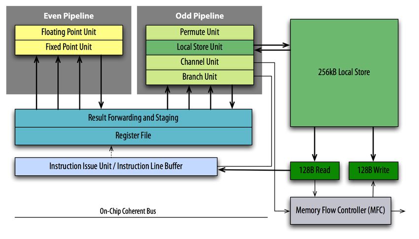
MPICH1 [16], MPICH2 [15], and OpenMPI [13]. Figure 3 compares these li-
braries using NetPIPE [23] version 3.6.2. The figure might not directly indicate
how each of the implementations will perform with a particular application but
should give a general sense of what to expect and serve as a reference point
quick sanity check of a particular installation. Figure 3 (top) shows the achiev-
able bandwidth in relation to the message size. MPICH1 clearly delivers lowerperformance than the other two implementations. Even for MPICH2 and Open-
MPI, however, only 60% of the theoretical peak bandwidth can be achieved. We
believe that this is due to the fact that the operating system can access the
hardware only by means of the hypervisor. For the same reason, the latency
associated with MPI sends/receives is very high (up to 3× higher than what is
commonly achieved on a Gigabit network) as shown on Figure 3 (bottom).
MPI performance on the PS3 cluster: Bandwidth
700
MPICH1 1.2.7
MPICH2 1.0.5
600 OpenMPI 1.3
500
bandwidth (Mb/s)
400
300
200
100
0 0 1 2 3 4 5 6
10 10 10 10 10 10 10
message size (Bytes)
MPI performance on the PS3 cluster: Latency
450
MPICH1 1.2.7
MPICH2 1.0.5
400 OpenMPI 1.3
350
time (usec.)
300
250
200
150
100 0 1 2 3
10 10 10 10
message size (Bytes)
Fig. 3. Comparison of various MPI implementations using NetPIPE 3.6.2. Band-
width (top) and latency (bottom).4 A case study: Parallel Matrix-Matrix Product
Matrix-matrix product is one of the most important linear algebra kernels since
it represents the most computationally intensive operation on many applications.
For this reason, many parallel algorithms for matrix multiplication have been de-
veloped and extensively studied in the past. The Cannon [10], the PUMMA [12]
and the SUMMA [14,7] algorithms are noticeable examples and are still exten-
sively adopted in many high performance, linear algebra applications run on
parallel architectures (SUMMA is used in ScaLAPACK [11]). These algorithms
are highly optimized, provide good scalability and are easy to implement; more-
over, to carry on the local computations on each node, they rely on serial matrix
multiply for which implementations exist that can run very close to the peak
performance of the node. For these reasons, the parallel matrix-matrix prod-
uct can be considered a good benchmark to evaluate the performance and the
scalability of a parallel machine.
The main difference between these (and other) algorithms is in the way they
match different architectures and connection topologies. All of them have almost
the same ratio between the number of floating point operations and the amount
of data that is moved on the interconnect. Since our cluster has only four nodes
connected through a Gigabit network, the algorithm we chose for benchmarking
is SUMMA.
4.1 Evaluating the SUMMA algorithm: performance models and
experimental results
The SUMMA algorithm for parallel matrix multiplication is very flexible yet
very effective. Since SUMMA can be defined as a blocked algorithm, high per-
formance is achieved using BLAS-3 operations to carry on local computations
(specifically, the _GEMM operation for matrix-matrix multiplication). Block-cyclic
storage formats can be used with SUMMA, which allows for better exploitation
of the fast BLAS-3 operations on each node. Moreover, MPI communications and
local computations can be easily overlapped, providing even more performance
and scalability. The algorithm was introduced in [14] and a variant that contains
a method for overlapping communications and computations was presented al-
most at the same time by Agrawal et al. [7]. In the following discussion we are
assuming a non-cyclic but blocked storage for the matrices. Figure 4 shows how
matrices are partitioned on a 2x2 processor grid. Each partition is stored locally
in a blocked format where blocks are arranged in a row-major fashion, and single
elements are also stored in row-major format inside each block. Even though the
block storage is not a strict requirement on “standard” architectures (but is still
recommended to achieve higher data locality and thus, higher performance), it is
almost mandatory on the Cell since non-blocked storage may result in extremely
poor performance.
The SUMMA algorithm proceeds through successive steps, where at step i
the block column A∗i and the block row Bi∗ are multiplied in order to update
C. The steps of the SUMMA algorithm are described in Algorithm 1.0 1 2 61 62 63
64 65 66
0 1 2 3 4
5 6 7
0 1
2 3
Fig. 4. Matrix blocking and partitioning on a 2x2 processors grid.
Algorithm 1 SUMMA
1: for i = 1 to n/nb do
2: if I own A∗i then
3: Copy A∗i in buf1
4: Bcast buf1 to my proc row
5: end if
6: if I own Bi∗ then
7: Copy bi∗ in buf2
8: Bcast buf2 to my proc column
9: end if
10: C = C + buf 1 ∗ buf 2
11: end for
Figure 5 gives a graphical description of the operations performed at each
step. The top-left part of Figure 5 shows how the block column A∗i is broadcasted
to the processors row while the top-right part shows how the block row Bi∗ is
broadcasted to the processors column, i.e., steps four and eight in Algorithm 1
respectively. The bottom part represents the local update C = A∗i · Bi∗ in step
ten of Algorithm 1.
Since the algorithm is very simple, it is possible to easily produce a very ac-
curate performance model under the assumption that, if many decoupled com-
munications are performed at the same time, they do not affect each other per-
formancewise. This assumption holds when a high quality switch is used for the
cluster network. Another assumption made is that, broadcasting a message to n
processes is as expensive as performing n point-to-point sends. Finally, we will
also assume that the algorithm is mapped on a square processors grid. To de-
velop the model we can simply focus on a single step of the algorithm. Since MPI
sends are more expensive than receives, the time of a single loop of Algorithm 1
for each process is limited by the time of the process that has to perform bothA B
0 1 0 1
2 3 2 3
0 1 C
0 1
3
2
2 3
Fig. 5. Steps of the SUMMA algorithm.
the broadcasts at steps 4 and 8 of Algorithm 1. This process has to broadcast a
√ √
message to the np − 1 processes along its row and a message to the np − 1
processes along its column (where np is the total number of processes). This
makes a total
√
nmsg = 2 · ( np − 1) (1)
Each of these messages is of size
n
msgsize = √ · nb · f psize (2)
np
where nb is the block size and f psize is the size in bytes of a single element (4
for single precision, 2 for double. . . ). The overall time spent in communications
is, thus
msgsize · nmsg
tcomm = (3)
bw
where bw is the network bandwidth. The number of floating point operations
(the same for each process) performed at each step is
n n n2
ops = 2 · √ · √ · nb = 2 · · nb (4)
np np npAssuming that these operations can be performed at the Cell peak, the time
spent in computations is
ops 2 · n2 /np · nb
tcomp = = (5)
peak peak
The total time spent in each step is then
tstep = tcomm + tcomp (6)
Since every process performs ops floating point operations in tstep time, the
overall performance is
ops·np 2·n2 ·nb
perf = tstep
= √
√n ·nb·f psize·2·( np−1)
2·n2 /np·nb np
peak
+ bw
n (7)
= psize √
f√
·( np−1)
n/np np
peak
+ bw
The performance of the SUMMA algorithm can be greatly improved by over-
lapping communications with computations. This well known rule for efficient
parallel programming can be easily applied to our case; since the computations
are offloaded to the SPEs on each node, the PPE, instead of staying idle waiting
for the completion of the local _GEMMs, can take care of the communications. An
almost perfect overlap can be achieved by means of a simple double buffering
where the data for step k + 1 of Algorithm 1 are broadcasted in advance at step
k. Thus, the time for each step of Algorithm 1 becomes
tstep = max(tcomm , tcomp ) (8)
and the performance model
ops·np 2·n2 ·nb
perf = tstep
= √
√n ·nb·f psize·2·( np−1)
!
2·n2 /np·nb np
max peak
, bw
n (9)
= psize √
f√
·( np−1)
!
n/np np
max peak
, bw
Figure 6 shows a comparison between the expected performance with and
without communications/computations overlapping as computed with models
in equations (8) and (7), respectively. Figure 6 also shows that, for large prob-
lems, linear speedup can be theoretically achieved when overlapping is imple-
mented. This is due to the surface-to-volume effect which comes into play when
a minimum problem size is reached for which local computations become more
expensive than MPI communications. The effect of the surface-to-volume phe-
nomenon is reflected by the presence of a knee in the model data.
Our implementation of the SUMMA algorithm offloads the local computa-
tions at step 10 of Algorithm 1 to the SPEs. Table 1 shows the performance ofSUMMA on a 2x2 ps3 grid − Models
600
500
400
Gflop/s
300
200
100
with overlap
without overlap
0
0 0.5 1 1.5 2
problem size x 10
4
Fig. 6. Models for the performance of the SUMMA algorithm with and without
communications/computations overlapping. The graph has been plotted assum-
ing np = 4, f psize = 4 (single precision), bw = 600M b/s and peak = 25.6 · 6 =
153.6Gf lop/s.
Performance of
local computations
# SPEs Gflop/s
1 25.04
2 50.07
3 75.08
4 100.08
5 124.68
6 149.85
Table 1. Local GEMM performance.
the code that executes the local _GEMM using different numbers of SPEs from 1
up to the six available on the PS3 Cell processor. Local computations are per-
formed at a speed not lower than 97 percent of the peak performance of a single
processor.
While the local _GEMMs for step k of the Algorithm 1 are executed on the
SPEs, the PPE can take care of the communications broadcasting the data
needed for step k + 1. This yields an almost perfect overlapping of communi-
cations and computations that permits to hide the less expensive of the two
phases.
Figure 7 shows part of the execution log for the SUMMA algorithm on a 2x2
processor grid. This figure shows how local computations are completely hidden
behind communications; this is due to the fact that, for the problem size usedFig. 7. Communication path for the SUMMA algorithm on a 2x2 PS3 nodes
grid.
in this figure (i.e., 6144), the communications are still more expensive than the
computations (see Figure 6).
SUMMA on a 2x2 ps3 grid − 1 SPE SUMMA on a 2x2 ps3 grid − 6 SPEs
600 Model 600
Linear speedup
Measured
500 500
400 400
Memory limit Memory limit
Gflop/s
Gflop/s
Surface−to−Volume
300 300
Surface−to−Volume
200 200
Linear speedup 100
100 Model
Measured
0 0
0 1000 2000 3000 4000 5000 6000 7000 8000 0 0.5 1 1.5 2
problem size problem size 4
x 10
Fig. 8. The measured performance for the SUMMA algorithm on a 2x2 PS3
processor grid. A comparison is made with the theoretical results obtained from
the model in equation (8).Figure 8 shows the experimental results obtained running our SUMMA im- plementation on a 2x2 PS3 nodes grid. A comparison with the model in equa- tion (9) is presented in the case where one SPE is used for the local computations (left) and where all the six available SPEs are used (right). The cost of the local computations is very small when all the six SPEs are used; this means that the surface to volume effect only comes into play for very big problem sizes (see Fig- ure 8 (right)). Due to the system limitations in memory (only 256 MB available on each node), it is not possible to have matrices bigger than 6144, which is pretty far from the point where linear speedup can be achieved (around 16000). When only one SPE is used on each node, the cost of the local computations is relatively much higher (a factor of six) and thus the surface-to-volume effect is reached at problem sizes within the limits of the system as shown in Fig- ure 8 (left). Since the Cell processor can perform double precision arithmetic at a much lower rate than single precision (a factor of 14), it is possible to achieve linear speedup within the system memory limits with a double precision SUMMA implementation. Figure 8 also shows that the model in equation (9) is very accurate. 5 Conclusions Although the PlayStation 3 seems to be an attractive solution for high perfor- mance computing due to its high peak performance and low cost (close to $4 per Gflop/s), there are many serious limitations that have to be taken into account. We list some of the difficulties in achieving high performance. Main memory access rate. The problem applies to the CELL processor and, frankly speaking, most modern processors and is due to the fact that execu- tion units can generate floating point results at a speed that is much higher than the speed at which the memory can feed data to the execution units. The main memory of the CELL processor is capable of a 25.6 GB/s peak transfer rate, while each SPE has a peak performance of 25.6 Gflop/s in single precision. For a 4 byte long, single precision floating point value, a single SPE has to perform four floating point operations in order to hide the communication. If six SPEs operate concurrently, 4 × 6 = 24 operations have to be performed on each single precision value in order to hide the commu- nication. The ratio cannot be achieved, for example, on sparse linear algebra operations, which can be performed, at best, at the speed of the memory, which results in the efficiency of only 12.5 percent of the theoretical peak. Network interconnect speed. The PlayStation 3 is equipped with a GigaBit Ethernet network interface. The capacity of this interconnect is out of bal- ance if compared with the theoretical peak performance of each node. Only computationally intensive applications can benefit from connecting multiple PS3s together to form a cluster. Computation, even as floating point inten- sive as dense matrix multiply, cannot be effectively parallelized over many PS3s.
Main memory size. The PlayStation 3 is equipped with only 256 MB of main
   memory. This represents a serious limitation when combined with the slow-
   ness of the network interconnect. The example of the SUMMA parallel algo-
   rithm for dense matrix-matrix multiplication described in Section 4 clearly
   shows that linear speedup can be achieved only for problem sizes that are
   at least three times bigger than what is possible with only 256 MB of local
   memory.
Double precision performance. Peak performance of double precision float-
   ing point arithmetic is a factor of 14 below the peak performance of single
   precision. Computations that demand full precision accuracy will see a peak
   performance of only 14.4 Gflop/s (almost 11 Gflop/s on the PlayStation 3).
Programming paradigm. The most attractive features of the CELL proces-
   sor are its simple architecture and the fact that all its functionalities can be
   fully controlled by the programmer. In most other common processors, per-
   formance can only be obtained with a good exploitation of cache memories
   whose behavior can be controlled by the programmer only indirectly. As a re-
   sult, the performance of applications developed for the CELL architecture is
   very predictable and straightforward to model; it is possible to get very close
   to the peak performance of the processor, much more than what can be done
   on cache based processors. This high performance and predictability, how-
   ever, comes at a cost. Writing efficient and fast code for the CELL processor
   is, in fact, a difficult task since it requires a deep knowledge of the processor
   architecture, of the development environment, and some experience. High
   performance can only be achieved if very low level code is produced that is
   on the border line between high level languages and assembly. Besides re-
   quiring a lot of effort, source code developed for the CELL processor is not
   portable at all on other architectures. Even though higher level programming
   models have been proposed for the CELL processor (see [8,6,5]), it is only
   possible to achieve a small portion of the processor’s performance relying on
   them.
   The bottom line is that the PlayStation 3’s attractiveness for scientific com-
putations will depend on the application’s characteristics. For many applications,
the limitations noted above will render the PlayStation 3 ineffective for clustering
and severely limited for many scientific computations.

References
 1.   http://fedoraproject.org.
 2.   http://www.ydl.net.
 3.   http://whitesanjuro.googlepages.com.
 4.   http://www.keshi.org/moin/moin.cgi/PS3/Debian/Live.
 5.   PEAKSTREAM. http://www.peakstreaminc.com/.
 6.   RAPIDMIND. http://www.rapidmind.net/.
 7.   R. C. Agarwal, F. G. Gustavson, and M. Zubair. A high-performance matrix-
      multiplication algorithm on a distributed-memory parallel computer, using over-
      lapped communication. IBM J. Res. Dev., 38(6):673–681, 1994.
8. P. Bellens, J. M. Perez, R. M. Badia, and J. Labarta. CellSs: a programming model
for the Cell BE architecture. In Proceedings of the 2006 ACM/IEEE Conference
on Supercomputing, 2006.
9. Alfredo Buttari, Piotr Luszczek, Jakub Kurzak, Jack Dongarra, and George
Bosilca. SCOP3: A rough guide to scientific computing on the PlayStation 3.
version 0.1. Technical Report UT-CS-07-595, Innovative Computing Laboratory,
University of Tennessee Knoxville, April 2007.
10. Lynn Elliot Cannon. A cellular computer to implement the kalman filter algorithm.
PhD thesis, 1969.
11. J. Choi, J. Demmel, J. Dhillon, J. Dongarra, S. Ostrouchov, A. Petitet, K. Stanley,
D. Walker, and R. C. Whaley. ScaLAPACK: A portable linear algebra library for
distributed memory computers. LAPACK Working Note, 95, 1995.
12. Jaeyoung Choi, Jack J. Dongarra, and David W. Walker. PUMMA: Parallel Uni-
versal Matrix Multiplication Algorithms on distributed memory concurrent com-
puters. Concurrency: Practice and Experience, 6(7):543–570, 1994.
13. Edgar Gabriel, Graham E. Fagg, George Bosilca, Thara Angskun, Jack J. Don-
garra, Jeffrey M. Squyres, Vishal Sahay, Prabhanjan Kambadur, Brian Barrett,
Andrew Lumsdaine, Ralph H. Castain, David J. Daniel, Richard L. Graham, and
Timothy S. Woodall. Open MPI: Goals, concept, and design of a next generation
MPI implementation. In Proceedings, 11th European PVM/MPI Users’ Group
Meeting, pages 97–104, Budapest, Hungary, September 2004.
14. R. A. Van De Geijn and J. Watts. SUMMA: scalable universal matrix multiplica-
tion algorithm. Concurrency: Practice and Experience, 9(4):255–274, 1997.
15. William Gropp. MPICH2: A new start for MPI implementations. In Dieter Kran-
zlmüller, Peter Kacsuk, Jack Dongarra, and Jens Volkert, editors, Recent Advances
in Parallel Virtual Machine and Message Passing Interface, number LNCS2474 in
Lecture Notes in Computer Science, page 7. Springer Verlag, 2002.
16. William D. Gropp and Ewing Lusk. User’s Guide for mpich, a Portable Implemen-
tation of MPI. Mathematics and Computer Science Division, Argonne National
Laboratory, 1996. ANL-96/6.
17. H. P. Hofstee. Power efficient processor architecture and the Cell processor. In Pro-
ceedings of the 11th Int’l Symposium on High-Performance Computer Architecture,
2005.
18. IBM. Cell Broadband Engine Architecture, Version 1.0, August 2005.
19. J. A. Kahle, M. N. Day, H. P. Hofstee, C. R. Johns, T. R. Maeurer, and D. Shippy.
Introduction to the Cell multiprocessor. IBM J. Res. & Dev., 49(4/5):589–604,
2005.
20. Mike Kistler, Michael Perrone, and Fabrizio Petrini. Cell Multiprocessor Intercon-
nection Network: Built for Speed. IEEE Micro, 26(3), May-June 2006. Available
from http://hpc.pnl.gov/people/fabrizio/papers/ieeemicro-cell.pdf.
21. Jakub Kurzak, Alfredo Buttari, and Jack Dongarra. Solving systems of linear
equations on the cell processor using Cholesky factorization. Technical Report UT-
CS-07-596, Innovative Computing Laboratory, University of Tennessee Knoxville,
April 2007. LAPACK working note 184.
22. D. Pham, S. Asano, M. Bolliger, M. N. Day, H. P. Hofstee, C. Johns, J. Kahle,
A. Kameyama, J. Keaty, Y. Masubuchi, M. Riley, D. Shippy, D. Stasiak,
M. Suzuoki, M. Wang, J. Warnock, S. Weitzel, D. Wendel, T. Yamazaki, and
K. Yazawa. The design and implementation of a first-generation CELL processor.
In IEEE International Solid-State Circuits Conference, pages 184–185, 2005.
23. Q. Snell, A. Mikler, and J. Gustafson. Netpipe: A network protocol independent
performace evaluator, 1996.24. Sun Microsystems. UltraSPARC IV Processor Architecture Overview, February
2004.
25. Sun Microsystems. The UltraSPARC T1 Processor - High Bandwidth For Through-
put Computing, December 2005.You can also read