Low-Latency Immersive 6D Televisualization with Spherical Rendering
←
→
Page content transcription
If your browser does not render page correctly, please read the page content below
Low-Latency Immersive 6D Televisualization with Spherical Rendering
                                                                                           Max Schwarz∗ and Sven Behnke

                                            Abstract— We present a method for real-time stereo scene               Cameras

                                                                                                                                                                                 2×4K Video
                                         capture and remote VR visualization that allows a human

                                                                                                                                                            Head Pose
                                         operator to freely move their head and thus intuitively control
                                         their perspective during teleoperation. The stereo camera is                                                                   150 ms
                                         mounted on a 6D robotic arm, which follows the operator’s
                                         head pose. Existing VR teleoperation systems either induce high
                                                                                                                                                             Spherical Rendering
arXiv:2109.11373v1 [cs.RO] 23 Sep 2021

                                         latencies on head movements, leading to motion sickness, or
                                         use scene reconstruction methods to allow re-rendering of the

                                                                                                                                                            Head Pose

                                                                                                                                                                                  Eye Views
                                         scene from different perspectives, which cannot handle dynamic
                                         scenes effectively. Instead, we present a decoupled approach                                                                   11 ms
                                         which renders captured camera images as spheres, assuming
                                         constant distance. This allows very fast re-rendering on head                  Robot with 6D Head
                                         pose changes while keeping the resulting temporary distortions
                                         during head translations small. We present qualitative exam-
                                         ples, quantitative results in the form of lab experiments and a
                                         small user study, showing that our method outperforms other
                                         visualization methods.
                                                               I. I NTRODUCTION
                                            There are many ways to control robotic systems, from
                                         remote control over teleoperation to full autonomy. Tele-
                                         operation is highly relevant and valuable to the robotic
                                         research community, first of all because it allows to ad-
                                         dress tasks that are impossible to solve using state-of-the-
                                                                                                                                        Stereoscopic VR System
                                         art autonomous control methods—the human intellect and
                                         creativity in solving problems and reacting to unforeseen
                                                                                                                 Fig. 1. Our low-latency televisualization approach. The 2×4K video stream
                                         events is unmatched. Furthermore, teleoperation can generate            from a stereo pair of wide-angle cameras is rendered using a sphere model
                                         training examples for improving autonomy in the future.                 to the operator’s VR headset. On a fast timescale, operator movements are
                                         There are also immediate benefits for the economy and daily             handled without much latency by re-rendering from the new pose. The
                                                                                                                 operator’s pose is also streamed to the robotic system, which moves the
                                         life: Teleoperation can allow humans to work remotely in                cameras accordingly in 6D, although on a slower timescale.
                                         potentially dangerous environments, which is highly desir-
                                         able in situations like the current COVID-19 pandemic. This
                                         interest is embodied in new robotics competitions like the                2) a combination of calibration steps for camera intrinsics
                                         ANA Avatar XPRIZE Challenge1 and a multitude of other                        and extrinsics, hand-eye, and VR calibration; and
                                         past and ongoing competitions [1], [2].                                   3) an efficient rendering method that decouples the VR
                                            One important, if not the most important feature of a                     view from the latency-afflicted robot head pose, pro-
                                         teleoperation system is its capability to display the remote                 viding a smooth low-latency VR experience at essen-
                                         environment to the human operator in a convincing, immer-                    tially unlimited frame rate.
                                         sive way. Maintaining full situational awareness is necessary
                                         to both induce security and confidence for the operator as                                     II. R ELATED W ORK
                                         well as to solve tasks efficiently and robustly.                           Viewing a stereo camera video feed is one of the estab-
                                            We present a real-time scene capture and visualization sys-          lished methods for remote immersion, providing live imagery
                                         tem for teleoperated robots, which gives the human operator             with intuitive depth perception.
                                         wearing a head-mounted display full 6D control of the first-               Martins et al. [3] mount a stereo camera on a field robot
                                         person camera perspective. In summary, our contributions                developed for rescue applications. While the camera is fixed
                                         include:                                                                to the robot, its track-driven body can bend to adjust the
                                            1) A robotic head assembly equipped with a 180° 4K                   camera pitch angle. The operator wears a head-mounted
                                                stereo camera pair, capable of 6D movement with low              display, whose tracking pose is used to control the pitch
                                                latency;                                                         angle and the yaw angle of the entire robot. Roll motions
                                           ∗ Both authors are with the Autonomous Intelligent Systems group of   are simulated by rotating the camera images in 2D. The
                                         University of Bonn, Germany; schwarz@ais.uni-bonn.de                    authors report that the high latency on yaw changes was
                                           1 https://www.xprize.org/prizes/avatar                                confusing for operators. We also note that this method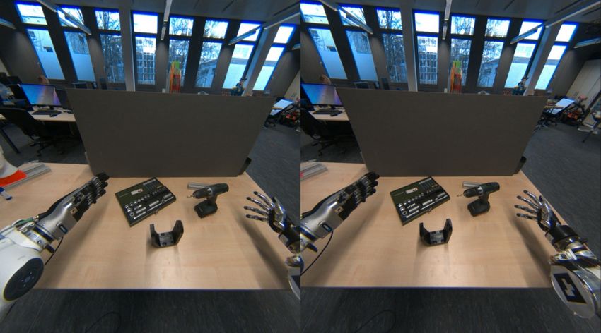
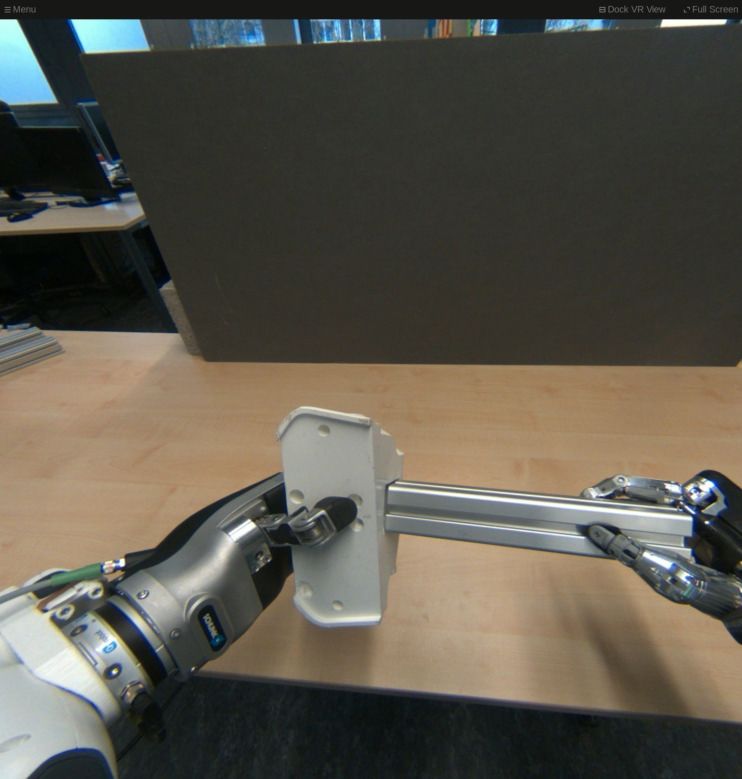
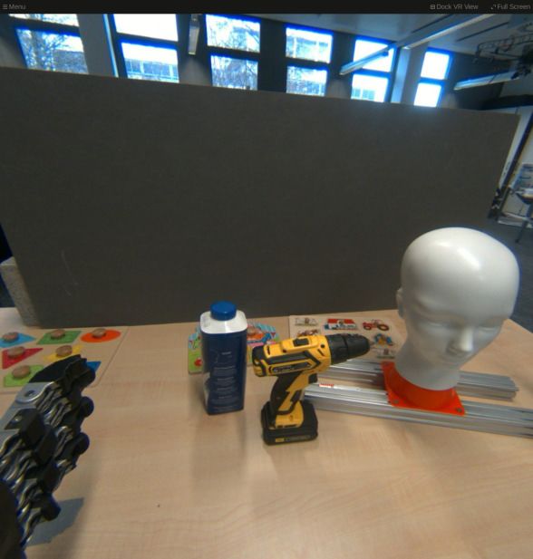
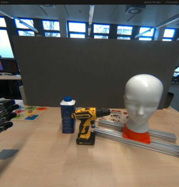
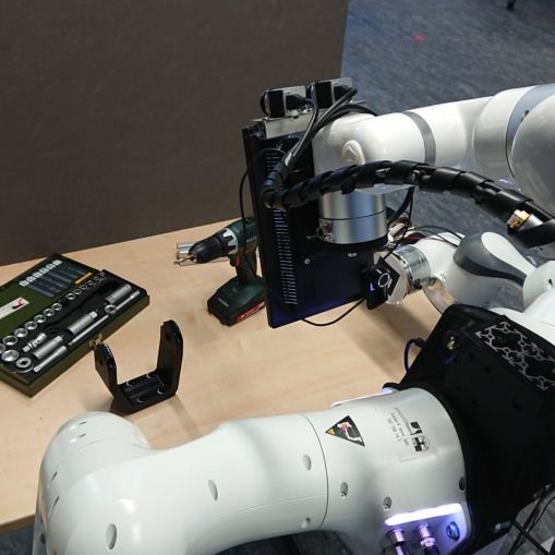
Fig. 2. Range of motion supported by our setup. We show the left eye view of the HMD, cropped to the central part for clarity. Note that the human
operator can easily change perspective and observe parts of the scene that were previously hidden.

will not accurately represent head orientations due to the                 almost no latency (requiring just a rendering step), changes in
decomposition into Euler angles, which are then applied at                 the scene itself typically only show up after longer delays—
different locations. In contrast, our method supports full 6D              if the scene representation supports dynamic content at all.
head movement (see Fig. 2) and reacts to pose changes with                 This makes these approaches completely unsuited for many
almost zero latency.                                                       telepresence situations, e.g. when interacting with a per-
   Zhu et al. [4] study whether head or gaze tracking is more              son or performing manipulation. Furthermore, reconstruction
suitable for camera orientation control. However, they do                  methods typically rely on depth, either measured by depth
not use a HMD but a 2D monitor for displaying camera                       cameras or inferred (SfM). Many materials and surfaces
images. Both head and gaze control modes operate in a                      encountered in everyday scenes result in unreliable depth
relative fashion, moving the camera in the indicated direction             and may violate assumptions made by the reconstruction
until the head/eye returns to its neutral position. The authors            method (e.g. transparent objects, reflections), resulting in
conclude that the gaze-based control method feels more                     wrong transformations or missing scene parts.
natural. In contrast, our system uses the absolute head pose                  RGB-D-based visualization solutions as the one by Whit-
to directly control the camera pose, leading to very natural               ney et al. [11], or Sun et al. [12], who display live RGB-D
and intuitive control of the camera.                                       data as point clouds for teleoperation of a Baxter robot, can
   This technique can also be seen in the work of Agarwal                  cope with dynamic scenes but still suffer from measurement
et al. [5], who control a robot’s head pose directly from a                problems and the inherent sparsity—the operator can often
human head pose measured with a Microsoft Kinect 2. Their                  look through objects.
robot head is only capable of 2D movement, pitch and yaw,                     Displaying a live stereo camera feed as done in our method
so the human pose is mapped with a neural network to the                   neatly sidesteps these issues, since the 3D reconstruction
lower-dimensional space. The robot head is not equipped                    happens inside the operator’s visual cortex. We address
with cameras, however.                                                     the resulting higher observer pose latency using a smart
   Very similarly, in one of the earliest works we could find,             rendering method discussed in the next section.
Heuring and Murray [6] control a stereo camera pair mounted
on a pan/tilt unit with sufficiently low latency to follow                                            III. M ETHOD
human head motions precisely.
   Conversely, Lipton et al. [7] combine stereo capture with               A. Robotic Platform & VR Equipment
VR to enable teleoperation, but mount their camera in a fixed                 Our robot’s head is mounted on a UFACTORY xArm 6,
location on the robot, providing only limited field of view.               providing full 6D control of the head (see Figs. 1 and 4).
   When the robot or its head cannot be moved fast enough,                 The robotic arm is capable of moving a 5 kg payload, which
latencies are introduced into a real-time teleoperation system.            is more than enough to position a pair of cameras and a
One particularly effective approach for removing latencies is              small color display for telepresence (not used in this work).
to display not the live camera feed, but a reconstructed 3D                Furthermore, the arm is very slim, which results in a large
scene, in which the operator can move freely without much                  workspace while being unobtrusive. Finally, it is capable of
latency. We explored this technique in our own work, where                 fairly high speeds (180 °/s per joint, roughly 1 m/s at the
we rendered reconstructed 3D laser maps of the environment                 end-effector), thus being able to match dynamic human head
to the user [8] and displayed textured meshes generated                    movements.
from a live RGB-D feed [9]. In both cases, we used a VR                       We chose two Basler a2A3840-45ucBAS cameras for the
headset which allowed the user free movement inside the                    stereo pair, which offer 4K video streaming at 45 Hz. The
reconstructed data with low latency. Later on, we improved                 cameras are paired with C-Mount wide-angle lenses, which
on these techniques in Stotko et al. [10] by displaying a                  provide more than 180° field of view in horizontal direction.
high-fidelity 3D mesh of the environment generated from an                 We also experimented with Logitech BRIO webcams with
automatically moving RGB-D camera mounted on the end-                      wide-angle converters, which offer auto-focus but can only
effector of a mobile manipulator.                                          provide 30 Hz at 4K, resulting in visible stutters with moving
   Visualizing reconstructed scenes has the disadvantage that              objects. The Basler cameras are configured with a fixed
although the system reacts to observer pose changes with                   exposure time (8 ms) to reduce motion blur to a minimum.
Thead (θ)
                                                                                                          Tcam

                                                                                                                                 Tmark
                                                                                     Tmount

                                                                                                          Tarm (θ)

                                                                       Fig. 4. Frames involved in the calibration procedure. Transformations
Fig. 3. Raw image from one of the wide-angle cameras. The horizontal   colored yellow are computed using forward kinematics from measured joint
field of view is higher than 180°.                                     angles while blue transformations are optimized. The auxiliary transform
                                                                       Tmarker is optimized, but not used in the calibrated system. Note: The camera
                                                                       FoV is shown for illustration purposes and is not to scale.

   The robot head is mounted on a torso equipped with two
Franka Emika Panda arms and anthropomorphic hands.                     left and right camera image frame as follows:
   The operator wears an HTC Vive Pro Eye head-mounted
                                                                                   −1     −1
display, which offers 1440×1600 pixels per eye with an                   pL = fµ (Tcam · Thead (θ) · Tmount · Tarm (θ) · Tmark ),               (1)
                                                                                         −1     −1
update rate of 90 Hz and 110° diagonal field of view. While              pR = fγ (TRL · Tcam · Thead (θ) · Tmount · Tarm (θ) · Tmark ), (2)
other HMDs with higher resolution and/or FoV exist, this
headset offers eye tracking which will be beneficial for               where Tarm (θ) and Thead (θ) are the poses of the arm and head
building telepresence solutions in future work. As can be              flanges relative to their bases for the current joint configura-
seen, the camera FoV is much larger than the HMD FoV,                  tion θ, and f is the double-sphere projection function with
which ensures that the visible FoV stays inside the camera             parameters µ and γ found above.
FoV even if the robot head should be lagging behind the                   We collect samples with known 2D pixel coordinates
operator’s movement.                                                   p̂L and p̂R extracted using the ArUco marker detector of
                                                                       the OpenCV library. During sample collection, the head
   The VR operator station is driven by a standard PC
                                                                       continuously moves in a predefined sinusoidal pattern while
(Intel i9-9900K 3.6 GHz, NVidia RTX 2080), connected via
                                                                       the robot’s arm is moved manually using teach mode. Sample
Gigabit Ethernet to the robot computer (same specifications).
                                                                       collection takes about 5 min for an engineer.
                                                                          Finally, we minimize the squared error function
B. Calibration
                                                                                            N
                                                                                            X
   Before the system can be used, multiple transforms and                            E=           ||pL − p̂L ||22 + ||pR − p̂R ||22             (3)
parameters need to be calibrated. We devised a principled                                   i=1
approach starting at camera intrinsic calibration over hand-           over all N samples using the Ceres solver, yielding optimal
eye calibration on the robot side, to VR calibration on the            transforms Tcam and Tmount .
operator side.
   Since the cameras have very high FoV with significant               C. Head Control
fish-eye distortion (see Fig. 3), we use the Double-Sphere                The remaining question is how to transfer the head pose,
camera model [13] to describe the intrinsics. Its parameter            measured in the VR space, to the robot side. To initialize the
sets µ and γ for the left and right cameras, respectively, can         mapping, we keep the robot head in predefined nominal pose
                                                                         robot
be calibrated easily using the kalibr software package [14],           Tnom    , looking straight ahead. We ask the human operator to
just requiring an Aprilgrid calibration target. The kalibr             do the same and record the resulting head pose in VR space
                                                                         VR
software also estimates the extrinsic transformation between           Tnom  , taking care to remove any remaining undesirable pitch
the two cameras TRL .                                                  and roll component.
                                                                                                               robot
   As shown in Fig. 4, there are further extrinsic transforma-            During operation, the head pose Thead      is computed from
                                                                                              VR
tions to be calibrated, especially if one wants to accurately          the tracking pose Thead in straightforward fashion:
perform manipulation with a robotic arm. We follow a classic                             robot    robot     VR −1    VR
                                                                                        Thead  = Tnom   · (Tnom ) · Thead ,                     (4)
hand-eye calibration approach with an ArUco marker on the
robot’s wrist, with the goal of estimating Tcam , but also the         directly mapping the operator’s head movement to the robot’s
transformation Tmount between the mounting of the head arm             head.
and the robot arm, and Tmark , the pose of the marker on the              The head pose is smoothed by a recursive low-pass filter
wrist.                                                                 with a cut-off frequency of 100 Hz to remove very high
   We can compute the 2D pixel positions pL and pR in the              frequency components. It is also monitored for larger jumps,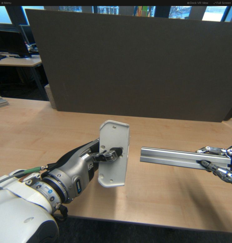
Using this design, head movements are immediately re-
                                                                                               acted to. Pure rotations of the head will have no perceptible
                                                                                               latency, since the wide-angle cameras will already have
                                                                      C
                                             r
                                                                     TV
                                                                                   r           captured the area the operator will look at. Translational
                                                                                               movements work as if everything is at a constant distance,
                             (a) Pure rotation                (b) Rotation + Translation       yielding distortions wherever this assumption does not hold
Fig. 5. Spherical rendering example in 2D. We show only one camera C                           (see Fig. 5). The amount of distortion can be quantified by
of the stereo pair, the other is processed analogously. The robot camera is                    the angular projection error γ and depends on the distance d
shown in white with its very wide FoV. The corresponding VR camera V ,
which renders the view shown in the HMD, is shown in green. The camera
                                                                                               to the object and the head translation ∆x (here perpendicular
image is projected onto the sphere with radius r, and then back into the                       to the view ray):
VR camera. Pure rotations (a) result in no distortion, while translations (b)
will distort the image if the objects are not exactly at the assumed depth.                                               d                 r
                                                                                                           γ = arctan           − arctan        .        (5)
                                                                                                                         ∆x                ∆x
Angular Error γ [◦ ]

                         5                                                                       Note that γ quickly saturates for large d against the value
                                                                                               π             r
                                                                                               2 − arctan( ∆x  ) (see Fig. 6). For d < r, the distortion can
                         0
                                                                                               become significant. In conclusion, it is important to choose
                       −5                                                                      r close to a typical minimum object distance. Of course, as
                                                                                               soon as the robot head catches up and moves into the correct
                       −10                                                                     pose, any distortion is corrected.
                             0        0.5          1        1.5        2        2.5        3
                                                 Real object distance d [m]                    E. Latency Improvements
Fig. 6. Angular error introduced by translation of the operator head by                           We found that we needed to take special care at nearly
∆x = 10 cm depending on the distance to the object. Since the spherical
reprojection assumes a distance of 1 m, we see no error at that distance.                      all parts of the pipeline to ensure low-latency operation with
The red dashed line shows the error upper bound for large distances d.                         the required time precision.
                                                                                                  Starting at the cameras, we wrote a custom driver which
                                                                                               uses the built-in timestamping feature of the cameras to
in which case we switch to a slower initialization mode that                                   obtain high-precision timing information in order to correlate
moves to the target pose with limited velocity.                                                images with head-arm transforms. Furthermore, it is nec-
                                                                                               essary to compress the image stream for transmission over
D. Spherical Rendering                                                                         Ethernet, since the raw stream bandwidth exceeds 350 MB/s.
   If operator and robot head poses matched exactly, the                                       For easy interoperability with standard ROS packages, we
camera images could be rendered immediately to the HMD                                         chose an MJPEG compression, which is done efficiently
by projecting each pixel in HMD image space to the cam-                                        on the GPU [15]. The resulting stream has a bandwidth
era images and looking up the corresponding color value.                                       of 30 MB/s, which is acceptable in our setup. If even less
However, when the poses are not identical, as is usually the                                   bandwidth is required, hardware-accelerated H.264 encoding
case, we have a 6D transform TCV between the virtual VR                                        could be a solution.
camera V (representing the operator’s eye) and actual camera                                      Furthermore, we developed a custom driver for the xArm,
position C. Traversing this transform requires 3D positions,                                   which provides joint position measurements at a high rate.
but we do not have depth information.                                                          This required modifications to the arm firmware. Our modi-
   Hence, we must make assumptions which will not impact                                       fied version can control and report joint positions at 100 Hz.
the result quality much, since the transform TCV will be quite                                 Its measurements are interpolated and synchronized with the
small. The simplest assumption is one of constant depth                                        timestamped camera images using the ROS tf stack.
for the entire scene. Since we are dealing with wide-angle                                        Finally, the VR does not use the standard
cameras, it is natural to assume constant distance, leading to                                 image transport ROS package, which cannot
spherical geometry around the camera. With this assumption,                                    decompress the two MJPEG streams with 4K resolution at
we can raycast from the VR camera V , find the intersection                                    45 Hz. Instead, we use the GPUJPEG decoder [15].
with the sphere, and find the corresponding pixel in the                                          All in all, these examples highlight that many off-the-
camera image (see Fig. 5).                                                                     shelf products are not designed for the required low-latency
   In practice, the rendering part is implemented in OpenGL                                    operation and manual adaptation requires considerable effort.
using the Magnum 3D Engine2 . We use the standard ras-                                                             IV. E XPERIMENTS
terization pipeline by rendering a sphere of radius r = 1 m
                                                                                               A. Quantitative Experiments
at the camera location. A fragment shader then computes
the pixel location (in C) of each visible point of the sphere                                     In a first experiment, we measured the total image latency
and performs a texture lookup with bilinear interpolation to                                   from acquisition start inside the camera to display in the
retrieve the color value.                                                                      HMD. For this, we used the timestamping feature of the
                                                                                               camera, with the camera time synchronized to the robot
             2 https://magnum.graphics                                                         computer time. Both computers are synchronized using the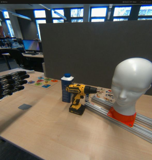
vop
0.6
Velocity [m/s] t1 t2 vrob
0.4 Initial
view
0.2
0
0.5 1 1.5 2 2.5
Time [s]
Fig. 7. Head movement latency experiment. Shown are the Cartesian
Adapted
velocities of the operator’s head vop and the robot’s head vrob during a fast view
(0.5 m/s) head movement. Vertical lines have been added to ease analyzing
latencies (start latency t1 ≈ 130 ms, finish latency t2 ≈ 100 ms).
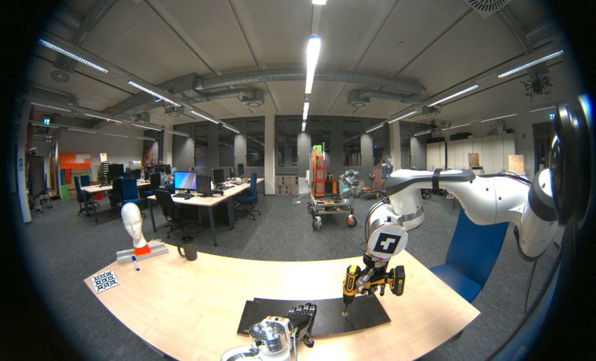
8 Fig. 9. Operator view (cropped) during the user study task. The peg has
20
Velocity [cm/s]
Deviation [cm]
∆s square cross section of 4×4 cm. The hole in the white plastic object is
6
vop 0.3 mm larger. In the bottom situation, the user repositioned their head to
4 10 better view the interfacing parts.
2
TABLE I
0 0
U SER STUDY SUCCESS RATES AND TIMINGS
5 10 15
Time [s] Visual mode Success Completion time [s]
Mean StdDev
Fig. 8. Head tracking performance. We show the distance ∆s of the VR
eye camera V from the robot camera C for the left eye stream. The operator a) Full 6D 7/7 71.0 50.6
was performing highly dynamic head movements. As expected, the position b) 3D orientation 7/7 111.7 87.5
deviation is highly correlated with operator head velocity vop . c) Fixed perspective 6/7 158.3 39.6
chrony NTP system, so that timestamps are comparable. Participants were asked to teleoperate the robot, perform-
Finally, the VR renderer compares the system time against ing a rather difficult peg-in-hole task involving grasping two
the camera timestamp at rendering each frame. On average, objects, and inserting one into the other with tight tolerances
the images are shown with 40 ms latency. A considerable (see Fig. 9). The task places high demands on the visual
fraction of this time is consumed by the camera exposure system since a) even small misalignments would prevent
time (8 ms) and USB transfer time (around 10 ms). success and b) the peg object was quite hard to hold and
Since the VR renderer achieves the maximum HMD slippage could only be detected visually. For controlling the
update rate of 90 Hz without difficulty, rotational head move- two robot arms and hands, the participants used a custom
ments have the same latency as in local VR applications, force-feedback exoskeleton system which is not the focus of
which is not noticeable—according to publicly available this work. The participants performed the task three times,
information, the Lighthouse VR tracking system operates with different visual modes:
with 250 Hz update rate3 . a) Full 6D: Entire pipeline with full 6D movement.
To analyze the total latency of head control, we plotted b) 3D orientation: The operator only controls the ori-
Cartesian velocities of the raw target head pose (as recorded entation of the head (similar to [3], [6]). The spherical ren-
by the VR tracking system) and the measured head pose dering system is used, but the camera spheres are translated
during a fast head motion (see Fig. 7). The latency varies to the HMD eye position. Notably, this variant can still react
along the trajectory, but the head comes to a stop roughly to orientation changes with low latency by re-rendering.
200 ms after the operator’s head stopped moving. We note c) Fixed perspective: The robot head orientation is
that this is a maximum bound of the latency; slower head fixed to a 45° downward pitch, focusing on the table in front
motions result in lower latencies. of the robot. The camera images are rendered directly to the
Furthermore, we analyzed the absolute deviation between HMD, i.e. the HMD pose has no effect. This is similar to
the HMD eye pose and the camera pose, i.e. the error that is devices sold as First-Person-View (FPV) glasses, which are
introduced during the spherical rendering step (see Fig. 8). commonly used in drone racing.
We note that even during fast motions, only minor distortions The order of the three trials was randomized to mitigate
were noticeable to the operator. effects from learning during the trials. Participants could
B. User Study attempt the task as often as they liked (with an assisting
We conducted a small user study in order to measure human resetting the objects on the table if moved out of
the immersiveness and efficacy of our pipeline. Due to the reach). When a maximum time of 5 min was reached without
ongoing COVID-19 pandemic, we were limited to immediate success, the trial was marked as failed.
colleagues as subjects, which severely constrained the scope Although the task itself was not the primary goal of the
of our study to seven participants. user study, effects of the visual mode on success rates and
average completion time can be observed (Table I). The full
3 https://en.wikipedia.org/wiki/HTC_Vive 6D mode never led to a failure and yielded the lowest average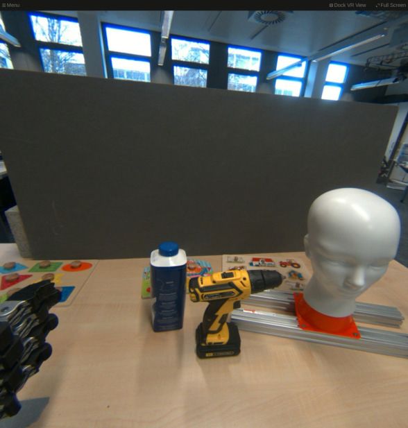
Did you maintain situational awareness?                      better
                                                                        6D
                                                                        3D
                             Could you clearly see the objects?
                                                                        Fixed
                              Could you judge depth correctly?

            Was the VR experience comfortable for your eyes?

                       Did you find and recognize the objects?

                              Was it easy to grasp the objects?

                         Was it easy to fit the objects together?

                                                                    1           2            3           4            5           6            7
Fig. 10. Statistical results of our user questionnaire. We show the median, lower and upper quartile (includes interquartile range), lower and upper fence,
outliers (marked with •) as well as the average value (marked with ×), for each aspect as recorded in our questionnaire.

completion time, although the standard deviation was quite                                                    R EFERENCES
high—mostly due to external effects such as the robot arms                       [1]    E. Krotkov, D. Hackett, L. Jackel, M. Perschbacher, J. Pippine, J.
requiring a reset after too much force was applied, but the                             Strauss, G. Pratt, and C. Orlowski, “The DARPA Robotics Challenge
                                                                                        finals: Results and perspectives,” Journal of Field Robotics, vol. 34,
skill level also varied highly from participant to participant.                         no. 2, pp. 229–240, 2017.
   After the three trials, we asked the participants questions                   [2]    H. Kitano, S. Tadokoro, I. Noda, H. Matsubara, T. Takahashi, A.
for each of the visualization modes, with answer possibilities                          Shinjou, and S. Shimada, “RoboCup Rescue: Search and rescue in
                                                                                        large-scale disasters as a domain for autonomous agents research,”
from the 1-7 Likert scale. From the results reported in                                 in Int. Conf. on Systems, Man, and Cybernetics (SMC), vol. 6, 1999.
Fig. 10, it is immediately visible that the fixed perspective                    [3]    H. Martins, I. Oakley, and R. Ventura, “Design and evaluation of
variant leads to significantly lower user acceptance. The                               a head-mounted display for immersive 3D teleoperation of field
                                                                                        robots,” Robotica, vol. 33, no. 10, p. 2166, 2015.
users reported that this was mainly due to inability to pan                      [4]    D. Zhu, T. Gedeon, and K. Taylor, “Head or gaze? Controlling remote
the camera and instead having to move the workpieces to                                 camera for hands-busy tasks in teleoperation: A comparison,” in
a better observable pose. Furthermore, the head translation                             Conf. of the Computer-Human Interaction SIG of Australia, 2010.
                                                                                 [5]    P. Agarwal, S. Al Moubayed, A. Alspach, J. Kim, E. J. Carter,
seems to have no impact on grasping the objects, but impacts                            J. F. Lehman, and K. Yamane, “Imitating human movement with
insertion—where it is beneficial to be able to look slightly                            teleoperated robotic head,” in International Symposium on Robot and
from the side to see the involved edges (compare Fig. 9).                               Human Interactive Communication (RO-MAN), 2016, pp. 630–637.
                                                                                 [6]    J. J. Heuring and D. W. Murray, “Visual head tracking and slaving
                V. D ISCUSSION & C ONCLUSION                                            for visual telepresence,” in International Conference on Robotics and
                                                                                        Automation (ICRA), vol. 4, 1996, pp. 2908–2914.
   We have demonstrated a method for 3D remote visual-                           [7]    J. I. Lipton, A. J. Fay, and D. Rus, “Baxter’s homunculus: Virtual
ization that does not rely on geometry reconstruction and                               reality spaces for teleoperation in manufacturing,” IEEE Robotics
                                                                                        and Automation Letters, vol. 3, no. 1, pp. 179–186, 2017.
is thus suited for highly dynamic scenes, but is still able                      [8]    T. Rodehutskors, M. Schwarz, and S. Behnke, “Intuitive bimanual
to deliver low-latency response to 6D head movements. The                               telemanipulation under communication restrictions by immersive 3D
user study shows that allowing full 6D head movement leads                              visualization and motion tracking,” in International Conference on
                                                                                        Humanoid Robots (Humanoids), 2015, pp. 276–283.
to faster task completion and better user acceptance when                        [9]    T. Klamt, M. Schwarz, C. Lenz, L. Baccelliere, D. Buongiorno,
compared with fixed-mount and pan-tilt systems, which are                               T. Cichon, A. DiGuardo, D. Droeschel, M. Gabardi, M. Kamedula,
still common in teleoperation.                                                          N. Kashiri, A. Laurenzi, D. Leonardis, L. Muratore, D. Pavlichenko,
                                                                                        A. S. Periyasamy, D. Rodriguez, M. Solazzi, A. Frisoli, M. Gust-
   There are also some points of the system that can be                                 mann, J. Roßmann, U. Süss, N. G. Tsagarakis, and S. Behnke,
improved. The work space of the arm used to move the head                               “Remote mobile manipulation with the Centauro robot: Full-body
is—in its present mounting position—limited and cannot                                  telepresence and autonomous operator assistance,” Journal of Field
                                                                                        Robotics, vol. 37, no. 5, pp. 889–919, 2020.
match the full motion range of sitting humans moving their                      [10]    P. Stotko, S. Krumpen, M. Schwarz, C. Lenz, S. Behnke, R. Klein,
torso and neck. For this, it would be interesting to investigate                        and M. Weinmann, “A VR system for immersive teleoperation and
a more biologically inspired joint configuration.                                       live exploration with a mobile robot,” in International Conference
                                                                                        on Intelligent Robots and Systems (IROS), 2019.
   While our method has been evaluated only in a seated                         [11]    D. Whitney, E. Rosen, E. Phillips, G. Konidaris, and S. Tellex,
configuration, it should be applicable with a completely                                “Comparing robot grasping teleoperation across desktop and virtual
mobile robot and operator as well. This can be investigated                             reality with ROS reality,” in Robotics Research, 2020.
                                                                                [12]    D. Sun, A. Kiselev, Q. Liao, T. Stoyanov, and A. Loutfi, “A new
in future research.                                                                     mixed-reality-based teleoperation system for telepresence and ma-
   Our work also does not focus on the transmission of data                             neuverability enhancement,” IEEE Transactions on Human-Machine
to remote sites. It is clear that for transmission over the                             Systems, vol. 50, no. 1, pp. 55–67, 2020.
                                                                                [13]    V. Usenko, N. Demmel, and D. Cremers, “The double sphere camera
Internet, bandwidth requirements would have to be lowered,                              model,” in Int. Conf. on 3D Vision (3DV), 2018, pp. 552–560.
e.g. through the use of more efficient video compression                        [14]    J. Rehder, J. Nikolic, T. Schneider, T. Hinzmann, and R. Siegwart,
codecs. The system should, however, be able to cope with                                “Extending kalibr: Calibrating the extrinsics of multiple IMUs and
                                                                                        of individual axes,” in Int. Conf. on Rob. and Aut. (ICRA), 2016.
typical latencies found on Internet connections (up to 200 ms                   [15]    P. Holub, J. Matela, M. Pulec, and M. Šrom, “UltraGrid: Low-latency
for connections halfway around the world).                                              high-quality video transmissions on commodity hardware,” in 20th
                                                                                        ACM International Conference on Multimedia, 2012, pp. 1457–1460.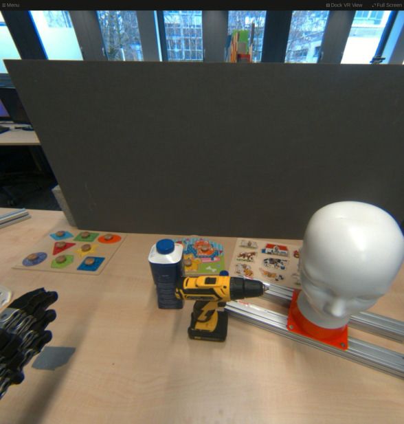
You can also read