MAGNETOSPHERIC MULTISCALE
←
→
Page content transcription
If your browser does not render page correctly, please read the page content below
National Aeronautics and Space Administration

PRESS KIT/March 2015

MAGNETOSPHERIC MULTISCALE:
Using Earth’s magnetosphere as a laboratory to study the microphysics of
magnetic reconnection
Contents

Media Contacts…………………………………………………………………………………….…3
Media Services Information…………………………………………………………………………4
Quick Facts………………………………………………………………………………………...…5
Science Objectives………………………………………………………………………………..…7
Science & Instrument Payload…………………………………………………………………..…9
NASA’s Launch Services Program…………………………………………………………….…15
Program/Project Management……………………………………………………………….……16

2
Media Contacts
NASA Headquarters
Dwayne Brown
Office of Communications
202-358-1726
dwayne.c.brown@nasa.gov

NASA Headquarters
Jennifer Rumburg
Heliophysics Division
202-358-2484
jennifer.rumburg@nasa.gov

NASA’s Goddard Space Flight Center
Susan Hendrix
Office of Communications
301-286-7745
susan.m.hendrix@nasa.gov

NASA’s Kennedy Space
Center
George Diller
Office of Communications
Launch Operations
321-861-7643
george.h.diller@nasa.gov

United Launch Alliance
Jessica Rye
Launch Vehicle
jessica.r.rye@ulalaunch.com

Southwest Research Institute
Maria Stothoff
Principle Investigator Institution
210-522-3305
maria.m.stothoff@swri.org

                                                      3
Media Services Information NASA Television Transmission For digital downlink information for each NASA TV channel, access to all three channels online and a schedule of programming for Magnetospheric Multiscale activities, visit: http://www.nasa.gov/ntv Audio Audio of the pre-launch news conferences on L-2 and L-1 and launch coverage will be available on “V- circuits” that can be reached by dialing 321-867-1220, -1240, 1260, or 7135. Launch Media Credentials News media interested in attending the launch must be accredited through the NASA News Center at Kennedy Space Center. To apply for credentials, visit: https://media.ksc.nasa.gov Journalists may contact the KSC news media accreditation office at 321-867-6598 or 321-867- 2468 for more information. Briefings Two pre-launch press briefings will be held at the KSC press site. A pre-launch mission briefing will be held March 10 at 1 pm EDT. A pre-launch science briefing is scheduled for March 11 at 1 pm EDT. Both of these press briefings will be carried live on NASA TV. NASA Television Coverage NASA TV coverage on launch day will begin at 8 p.m. EDT. For information about NASA Television coverage of the launch, visit: http://www.nasa.gov/ntv KSC News Center/Status Reports The NASA News Center at KSC will be staffed for the Magnetospheric Multiscale mission beginning four days before launch and can be reached at: 321-867-2468. Launch status reports will be recorded on the KSC news media Codaphone beginning Monday, March 9, 2015 by dialing 321-867- 2525. NASA Web Prelaunch and Launch Coverage NASA’s homepage will provide extensive prelaunch and launch day coverage of the MMS mission at: www.nasa.gov 4
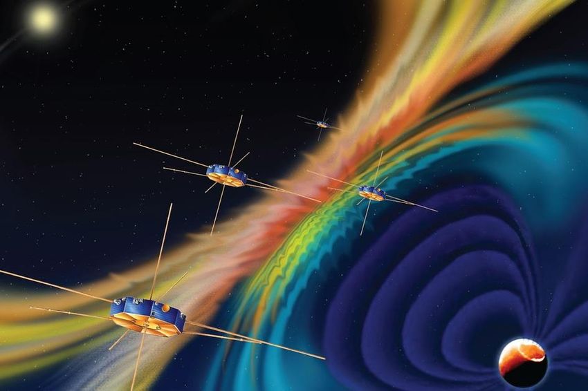
QUICK FACTS

Spacecraft: Each of the four MMS observatories are octagonal in shape, approximately 11 feet
across by 4 feet high. When stacked together inside the launch vehicle, the observatories are more
than 16 feet tall.

On Orbit Spacecraft Dimensions: Each observatory, with axial booms and wire booms extended,
grows to about 94 feet tall by 369 feet wide.

Fueled Mass: Each observatory weighs about 2,998 pounds (1360 kg).

Primary Power: Provided by eight solar array panels on each observatory, with secondary battery
energy storage for use during eclipses.

Propulsion System: Consists of 12 thrusters and four hydrazine propellant tanks located within the
central thrust tube on each observatory.

Spin Rate: Each observatory is spin-stabilized, with a spin rate of three revolutions per minute.

Attitude Information: Provided by four star cameras, two three-axis accelerometers and two sun
sensors. Thrusters are used for attitude and orbit adjustment maneuvers.

Position Information: Each observatory is equipped with a new navigator based on extremely
sensitive GPS equipment to provide absolute position information. This is necessary because the

5
observatories fly in an orbit higher than that of the GPS satellites, so they must rely on the weaker
signals from GPS satellites on the far side of Earth.

Launch Vehicle: Atlas V 421 provided by United Launch Alliance. The vehicle consists of an Atlas
first-stage engine and a Centaur second-stage engine, with two additional strap-on solid rocket
boosters.

Launch: March 12, 2015 at 10:44 pm ET, at the beginning of a 30-minute launch window, from
Launch Complex 41 located at Cape Canaveral Air Force Station, Florida.

Deployment: The first of four MMS observatories will be deployed into orbit beginning about one
hour, 32 minutes after launch and continue to deploy at five-minute intervals.

Commissioning phase: (time between deployment and commencement of primary science
mission) is 5.5 months.

Primary mission: Two years in addition to the commissioning phase.

Orbit:
MMS will travel in two highly elliptical, Earth orbits. Each orbit is designed to pass through two
separate areas of magnetic reconnection in near-Earth space. During the first 1.5 years MMS will fly
through the boundary where Earth's magnetic fields meet up with those from the sun. During the last
six months, MMS will focus on the night side of Earth, flying through reconnection sites in Earth’s
magnetic tail.

The first phase of the mission has an orbit that reaches 1,600 miles (2,550 km) altitude at its closest
approach to Earth and extends out to 43,500 miles (70,080 km) at its farthest. For the second
mission phase, the closest approach remains the same, but the orbit will extend out to 95,000 miles
(152,900 km) at its farthest point from Earth – this is about 41 percent of the distance to the moon.

NASA Investment:
$1.1 billion (design, development, launch and operations)

Historical Context: Several spacecraft, such as NASA's Time History of Events and Macroscale
Interactions during Substorms, or THEMIS, Explorer mission and the European Space Agency
(ESA) and NASA's Cluster, have previously gathered some data when they happened to fly through
a magnetic reconnection event in Earth's magnetosphere. However, MMS is the first mission
dedicated to the study of this phenomenon and will collect data at rates more than 100 times faster
than any previous mission.

16
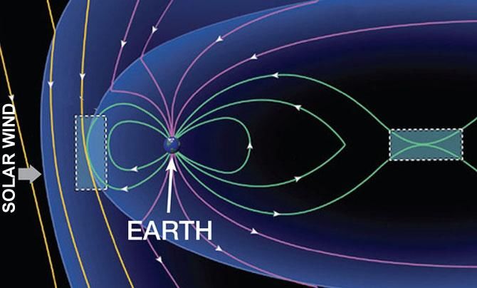
Science Objectives
Much of what scientists know about the small-scale physics of magnetic reconnection is derived from
theoretical studies, computer models and observations of reconnection events seen on the sun. A
better understanding, however, can only be obtained by measuring reconnection directly. MMS will
access a natural laboratory by traveling through the magnetic, plasma-filled environment around
Earth, called the magnetosphere.

MMS will fly directly through areas near Earth thought to be magnetic reconnection sites. On the sun-
side of Earth, reconnection can link the sun's magnetic field lines to Earth's magnetic field lines,
allowing material and energy from the sun to funnel into Earth's magnetic environment. On the night
side of Earth, reconnection is believed to help trigger aurora, also known as the Northern or Southern
lights.

Caption: MMS will use a two-phase orbit strategy to explore different regions where magnetic
reconnection often occurs, one on the day-side and the other on the night-side of Earth. Credit: NASA

7
By studying how reconnection occurs near Earth, MMS will vastly improve our understanding of how this fundamental process works elsewhere in the universe. Magnetic reconnection also occurs on the sun and is the driver for solar flares and massive eruptions of solar material called coronal mass ejections. Scientists also theorize that magnetic reconnection may be involved with a variety of astrophysical phenomena including how ultra-high-energy cosmic rays are accelerated so fast. Understanding reconnection better could even provide clues to developing a new source of efficient, clean, sustainable energy here on Earth, as magnetic reconnection can interfere with the success of fusion energy reactors. What Questions Will MMS Answer? MMS will vastly improve our understanding of magnetic reconnection by addressing these fundamental questions: What conditions determine when reconnection is initiated and when it ceases? What determines the rate at which reconnection occurs? What is the structure of the reconnection region? How does the plasma become demagnetized in the reconnection region? What is the role of turbulence in the reconnection process? How does reconnection accelerate particles to high energies? 16
Science and Instrument Payload Each MMS observatory carries 11 scientific instruments made up of 25 separate sensors. The numerous instruments are divided into three investigations, or groups: Hot Plasma Suite: to observe the nature of the charged gas, or plasma, present during reconnection Energetic Particles Detector Suite: to observe the fast-moving, energetic particles Fields Suite: to observe electric and magnetic fields and waves Hot Plasma Suite During a magnetic reconnection event, the changing shape of the magnetic fields sends the local charged particles, or plasma, off with a great push, creating something like a giant rush of wind. The hot plasma suite measures that plasma – a concrete, physical entity unlike the more abstract magnetic fields themselves – to learn more about what's happening during reconnection. The hot plasma suite of instruments includes the Fast Plasma Investigation and the Hot Plasma Composition Analyzer. Fast Plasma Investigation (FPI): The Fast Plasma Investigation observes the fast-moving plasma. Incoming particles pass through a filter which cherry picks certain particle speeds and directions and allows them to pass through to a sensor plate. When an incoming particle hits the sensor plate, millions of electrons come out the other side, so the instrument can detect the event. The whole process takes several nanoseconds. By filtering for specific energies, FPI can count the number of particles entering the instrument at different energies during any given time span. Past plasma detectors have relied on the spin of the spacecraft to gain a full view of its environment, but with only a journey of a fraction of a second through any given magnetic reconnection site, FPI must be much faster. Four sensors are used to detect the electrons and another four for the charged particles, known as ions. Each sensor is made of two spectrometers that each can scan through a 45-degree arc, resulting in a 90-degree field of view. Together the sensors can observe the entire sky. The box for each dual sensor and its components is as big as a small toaster oven, weighing in at about 15 pounds. In combination, FPI – consisting of the four dual electron spectrometers, the four dual ion spectrometers, and one data processing unit -- will produce a three-dimensional picture of the ion plasma every 150 milliseconds and of the electron plasma every 30 milliseconds. These frame rates are similar to those used in video and a factor of 100 times faster than what has been accomplished before for electrons. 9
The dual electron spectrometers and the processing unit, or IDPU, were built at NASA Goddard. The
dual ion spectrometers were built by Meisei Electric in Gunma, Japan, under the direction of the
Institute of Space and Aeronautical Sciences, a part of the Japanese Aerospace Exploration Agency.

Hot Plasma Composition Analyzer (HPCA):

While FPI gathers millisecond observations of the presence of the plasma, along with certain salient
details, the Hot Plasma Composition Analyzer is more concerned with detecting exactly which
particles are present. It gathers more detailed measurements but at a slower rate.

When a particle hits the carbon foil at the front of the sensor, it knocks off an electron. The HPCA
uses this electron to start a timer to measure the time it takes the original particle to hit a stop
detector. This time measurement can be used to determine the particle's speed, and this speed is
used to determine the mass of the original particle. The mass, in turn, is used to determine what
particle it was.

The material in Earth's magnetosphere is dominated by a different set of atoms than the material
streaming in from the sun with the solar wind: protons, singly charged helium and oxygen in the
magnetospheric plasma; protons and doubly charged helium in the solar wind. Consequently, using
the HPCA to observe what particles are present during any given event helps scientists determine
which kind of plasma was involved, and assess the effects of different particles.

Unlike FPI, the HPCA needs only one sensor. The instrument relies on the spin of the spacecraft to
view a sweep of the sky, gathering a set of observations every 10 seconds, the equivalent of half of
the spacecraft's spin.

The HPCA also has a unique capability never before flown. There are usually so many solar wind
protons compared to, for example, magnetospheric oxygen that mass spectrometers flown in the
past were overwhelmed -- and the oxygen signal was masked. HPCA uses radio frequency
oscillations to sweep the majority of solar wind protons away from the detector, without affecting the
magnetospheric oxygen, resulting in a 10- to 100-fold improvement in detection.

The HPCA was developed and built by the Southwest Research Institute in Austin, Texas.

Energetic Particles Detector Suite (EPD)

Magnetic reconnection both causes a bulk flow of plasma – not unlike a blowing wind -- and also can
pump up a small population of particles to incredibly high speeds and energies. The details of this
latter process remain undetermined, although many theories having been suggested. The Energetic
Particles Detector Suite will help distinguish between the theories and help determine whether this
acceleration only works for electrons or also for heavier particles, the charged atoms known as ions.
Short-term bursts of incredibly fast ions have been observed in the magnetic tail trailing behind
Earth, and it is possible that these are due to magnetic reconnection as well.

16
EPD also remotely senses the structure of a large space environment surrounding reconnection
sites, because it can observe particles coming in from far away. The instruments tracks ions that
move along giant circles, often larger than 2000 miles in diameter, and very fast electrons that move
up to 80% the speed of light.

EPD observes these high-speed particles through two instruments: the Fly's Eye Energetic Particle
Sensor and the Energetic Ion Spectrometer.

Fly's Eye Energetic Particle Sensor (FEEPS):

The primary job of FEEPS is to obtain nearly instantaneous all-sky measurements of how many
electrons of different energies and different arrival directions are present. The instrument relies on
solid-state detectors made of silicon, a semiconductor, much like those used in computer electronic
systems. Whenever a charged particle hits the detector, it initiates a current that can be used to
measure the energy of the original particle. There are two FEEPS instruments per spacecraft, and
together they provide 18 views in different directions simultaneously, giving rise to the "fly's eye" in
the instrument's name. FEEPS has two sets of sensors, one for electrons and one for ions. The
solid-state detectors within each of the electron "eyes" are covered by a 2-micrometer aluminum foil,
which keeps out the ions. The detectors for the ion views, on the other hand, have no aluminum foil
and are exceedingly thin so that electrons generally pass through without leaving a detectable
signal.

FEEPS was developed by The Aerospace Corporation of El Segundo, California.

Energetic Ion Spectrometer (EIS):

The Energetic Ion Spectrometer also gathers all-sky measurements of the energetic ions, collecting
information about their energy, their arrival direction and their mass. EIS can determine the mass of
these particles by measuring their velocity and total energy. The mass information helps determine
how many protons, helium ions and oxygen ions are present.

To measure the energy, EIS uses a solid-state detector like the one on FEEPS. Velocity is measured
using two very thin foils and a microchannel plate sensor. When an ion travels through the first foil, it
knocks a few electrons off. These electrons are deflected toward the microchannel plate, which can
amplify the signal, sending 1 million electrons out the other side -- just like the detectors used in the
plasma suite. The ion continues traveling to the second foil, where a similar process occurs. By
determining the time of flight between electron detection at the first and second foils, the instrument
can determine the velocity of the original incoming particle.

Combining the comprehensive ion measurements of EIS with the simpler ion measurements on
FEEPS allows researchers to determine the ion properties at a faster rate of 1/3 of a spacecraft spin,
a cadence that will sometimes be needed in the vicinity of fast-changing reconnection sites.

The Johns Hopkins University Applied Physics Laboratory in Laurel, Maryland led the EIS

11
development.

Fields Suite:
At the heart of magnetic reconnection lies the fact that magnetic fields change their configuration, so
the Fields suite has the important job of observing the magnetic fields themselves. It also observes
the key signatures of electric fields, which also change as part of the reconnection process. MMS will
measure electric fields simultaneously in all three dimensions with better precision than any previous
mission.

Because MMS will typically fly through a reconnection region in well under a second, the Fields suite
can gather information more than 1000 times per second -- the highest time-resolution
measurements on MMS. The Fields suite is made of six sensors: the Analog Fluxgate and Digital
Fluxgate magnetometers, the Electron Drift Instrument, the Spin-plane Double Probe, the Axial
Double Probe, and the Search Coil Magnetometer. The sensors all work together, in some cases
providing confirmation measurements, but also to cross-calibrate each other, thus providing very
precise measurements.

Analog Fluxgate (AFG) and Digital Fluxgate (DFG) Magnetometers:
The magnetometers provide two sets of similar measurements. The fluxgates carry a permeable
material that changes properties in response to the presence of magnetic fields. Measuring how they
change can be correlated to strength of the field down to a half a nanotesla – typical fields in the
regions of interest will be about 50 nanotesla.

The University of California in Los Angeles provided the AFB sensors. DFG instrumentation was
provided by the Space Research Institute of the Austrian Academy of Sciences in Graz, Austria.

Electron Drift Instrument (EDI):
The Electron Drift Instrument measures both the electric and magnetic fields by tracking the path of
electron beams through space. EDI sends a beam of electrons out into space using each of its two
Gun Detector Units. In the presence of magnetic fields, electrons travel in orbits that are nearly
circles, so over the course of about half a mile, the electron beam curves around on itself until it
comes back in to the second Gun Detector Unit. By measuring how long it takes the electrons to
circle back, one can calculate the strength of the magnetic fields through which the beam traveled.

When electric fields are present as well, then the electron beam will not make a perfect circle, but will
drift in a predictable way as it returns. By measuring the size of that sideways drift, one can calculate
the strength of the electric fields.

This technique of correctly capturing the electron beam was perfected for use on the joint European
Space Agency/NASA Cluster mission. On MMS, the EDI will take faster measurements than on
Cluster. Its strength, however, is not in its speed but in its precision, because knowing how much the
particles are being displaced in space due to an electron field is crucial for accurate measurements
by other instruments aboard MMS.

16
If needed, EDI can also be used solely as a detector, measuring all incoming electrons from space
as opposed to just tracking its own specialized electron beam. In this case, EDI can make
observations at rates of up to 1,000 times a second.

The EDI electric gun was developed at the Space Research Institute. EDI optics were developed at
the University of Iowa. The sensitive detector, the controlling electronics, and the overall integration
and operation of the EDI instrument is the responsibility of the University of New Hampshire in
Durham.

The Spin-plane Double Probe (SDP) and the Axial Double Probe (ADP):
MMS carries two sets of double-probe instruments. Each measures the voltage between two
electrodes to determine the electric field. Because the field changes are quite small, the electrodes
must be set as widely apart as possible to provide a robust signal. Thus the double probes sensors
reside at the ends of very long booms that deploy away from the main body of the observatory after
it is launched.

The Spin-plane Double Probe, or SDP, consists of four 200-foot wire booms with spherical sensors
at the end. These booms stick out of the sides of the observatory. The Axial Double Probe, or ADP,
is aligned through the center of the observatory, along its spin axis. It is made of two 30-foot
antennas.

Gathering accurate measurements while the spacecraft spins around is no small feat and the
accuracy of the probes is continually checked and calibrated against measurements made by EDI.

The SDP resulted from a collaboration between the University of New Hampshire, the Royal Institute
of Technology in Sweden, and the University of Colorado in Boulder. The University of Colorado
provided the ADP.

Search Coil Magnetometer (SCM):
The Search Coil Magnetometer provides direct measurements of changes in the magnetic fields,
using something called an induction magnetometer. The magnetometer contains a coil of wire
around a ferromagnetic material. It is a basic law of physics that a changing magnetic field near such
a coil will induce a voltage. Measurements of the voltage, therefore, can be used to determine how
the magnetic field changes.

The SCM was developed at the Laboratory for Plasma Physics in Paris, France.

FIELDS Central Electronics (CEB):
All the FIELDS measurements are coordinated, collected, and transmitted from a central electronics
system. This set of electronics was the responsibility of the University of New Hampshire, the Royal
Institute of Technology, the University of California in Los Angeles, the University of Colorado, and
the Space Research Institute.

13
In addition to the basic science instrument suites, the MMS payload includes:

Active Spacecraft Potential Control Devices (ASPOC):

The two ASPOCs neutralize the electrical potential of the spacecraft, limiting or eliminating spurious
electric fields that can contaminate measurements. This allows observations of the more
scientifically important low-energy ions and electrons.

The ASPOCs were developed at the Institut fuer Weltraumforschung of the Austrian Academy of
Sciences in Vienna.

Central Instrument Data Processor (CIDP):

The CIDP provides the interface between the instruments and the spacecraft Command and Data
Handling subsystem.

The CIDP was developed at the Southwest Research Institute.

For the location of each instrument as well as a more thorough description, visit:

         http://www.nasa.gov/mission_pages/mms/spacecraft/mms-instruments.html

16
NASA’s Launch Services Program
NASA turns to the engineers and analysts in its Launch Services Program, or LSP, to send robotic
spacecraft on their way for some of the most exciting and notable missions in the agency’s history.
The LSP is based at NASA’s Kennedy Space Center in Florida and boasts a roster of engineers and
technicians who specialize in all aspects of rocketry and spacecraft integration. LSP selects the
appropriate launcher for a mission’s spacecraft; in this case the United Launch Alliance Atlas V.
Often, this selection process takes place years before the first launch opportunity. The program then
provides oversight as the designs of the rocket and mission are integrated with each other.
As liftoff nears, teams oversee the launch vehicle’s engineering and manufacture and its integration
with the spacecraft.
LSP also conducts the countdowns for NASA’s scientific missions and provides additional quality
assurance along with other controls to ensure a successful mission.
Working with commercial rocket builders, planners have a number of rocket models to choose from,
ranging from the small, air-launched Orbital Sciences Pegasus to the workhorse Delta II rocket from
the United Launch Alliance, or ULA, to the powerhouse Atlas V, also from ULA. The catalog is
growing, too, with the addition of the SpaceX Falcon 9 and Orbital Sciences Antares rockets.
LSP moved its operations to Kennedy in 1998, becoming the first program based at the nation’s
premiere launch site. Since that time we have seen orbiters, landers and rovers to Mars, huge
observation spacecraft to Jupiter and the New Horizons mission launched to Pluto and the Kuiper
Belt, two astronomical locations that have never been seen up-close before.
Because some spacecraft need to fly in a different kind of orbit, LSP operates several launch centers
around the world. Cape Canaveral Air Force Station in Florida is adjacent to Kennedy Space Center
and hosts launches to place spacecraft in orbits that remain close to the equator. The LSP launch
team goes to Vandenberg AFB in California to run launches that require spacecraft to fly around the
world in a north-to-south orbit, known as a polar orbit. LSP also conducts launches from Kwajalein in
the Marshall Islands, Kodiak Island, Alaska, and NASA’s Wallops Flight Facility on Virginia’s eastern
Shore.
For Launch Services Program Updates and information, visit:
http://www.nasa.gov/centers/kennedy/launchingrockets/index.html
15Program/Project Management
The Magnetospheric Multiscale mission is a major scientific undertaking, involving institutions in the
United States as well as several partners in Europe and Japan.
MMS is the fourth NASA Solar Terrestrial Probes, or STP, Program mission. Goddard built,
integrated, and tested the four MMS spacecraft and is responsible for overall mission management
and mission operations. The Southwest Research Institute in San Antonio, Texas, leads the
Instrument Suite Science Team, with the University of New Hampshire leading the FIELDS
instrument suite. Science operations planning and instrument command sequence development will
be performed at the MMS Science Operations Center at the University of Colorado’s Laboratory for
Atmospheric and Space Physics in Boulder.
The STP Program, which is part of NASA’s Science Mission Directorate Heliophysics Division,
addresses fundamental science questions about the physics of space plasmas and the flow of mass
and energy through the solar system. The goal is to understand the processes that determine the
mass, momentum, and energy flow in the solar system from the Sun to planetary bodies, including
Earth, to the interstellar boundary.
Key STP program objectives are as follows:
1. To describe the system behavior of the magnetic variable star, our sun, and its interaction with
the entire solar system;
2. To understand the critical physics that link the sun, Earth, heliosphere, and the interstellar
medium;
3. To understand the processes and dynamics of the magnetosphere-ionosphere-upper
atmosphere system, the near space electromagnetic plasma environment surrounding the
Earth: and,
4. To develop and mature instrumentation and mission technologies with the potential of
advancing STP science.
These objectives support the Agency’s strategic goal to understand the sun and its effects on Earth
and the solar system, including space weather. STP missions study the fundamental processes
leading to evolutionary and future changes. Successive missions will focus on critical science targets
that systematically advance understanding of the coupled solar-heliosphere-terrestrial system. The
missions use a creative blend of in situ and remote sensing observations, often from multiple
platforms, to understand these fundamental physical processes, such as magnetic reconnection.
16You can also read