Messenger BLE User Manual - 9M02-7000-A101-EN - Cattron
←
→
Page content transcription
If your browser does not render page correctly, please read the page content below
Messenger BLE
   User Manual
   9M02-7000-A101-EN
Messenger BLE
         User Manual

         Revision History
           VERSION          DATE                    NOTES
                                                    Initial Release
           1.0.38           08/2020
           A                12/2020                 Document rebranded and contact information updated

   Any information furnished by Cattron™ and its agents is believed to be accurate and reliable. All specifications are subject to change without notice.
   Responsibility for the use and application of Cattron products rests with the end user since Cattron and its agents cannot be aware of all potential uses.
   Cattron makes no warranties as to non-infringement nor as to the fitness, merchantability, or sustainability of any Cattron products for any specific
   or general uses. Cattron Holdings, Inc., or any of its affiliates or agents shall not be liable for incidental or consequential damages of any kind. All
   Cattron products are sold pursuant to the Terms and Conditions of Sale, a copy of which will be furnished upon request. When used as a tradename herein,
   Cattron means Cattron Holdings, Inc. or one or more subsidiaries of Cattron Holdings, Inc. Cattron™, corresponding logos, and other marks are
   trademarks or registered trademarks of Cattron Holdings, Inc. Other marks may be the property of third parties. Nothing herein provides a license under
   any Cattron or any third party intellectual property right.

                                                                             2

9M02-7000-A101-EN
Version A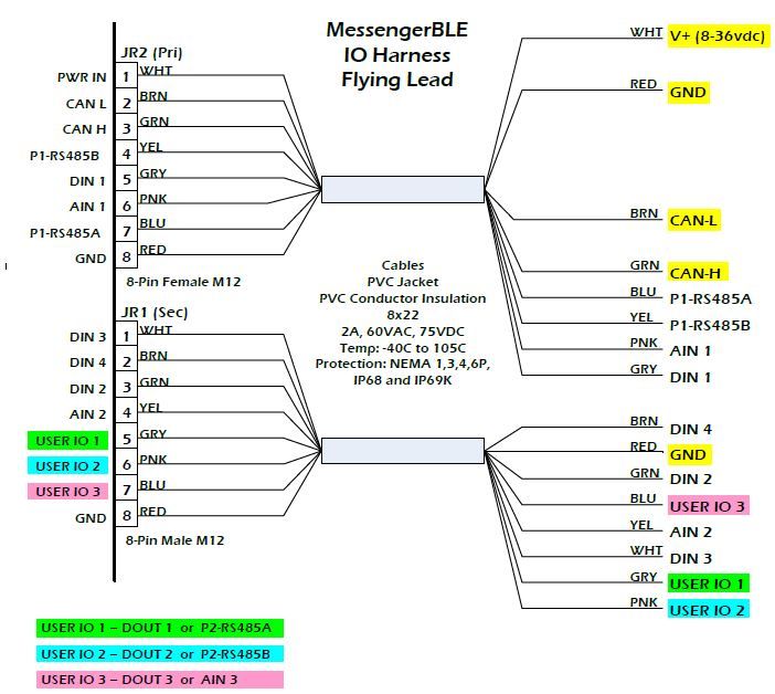
Messenger BLE
        User Manual

        Contents

        1   Description ...........................................................................................................................................................7
             1.1      Capabilities ...............................................................................................................................................7
             1.2      Monitoring .................................................................................................................................................7
             1.3      Host Server Communications ...................................................................................................................7
                        1.3.1 Event Codes ................................................................................................................................8
                        1.3.2 Positive Acknowledgement ..........................................................................................................8
                        1.3.3 Store and Forward Data Queue ..................................................................................................8
                        1.3.4 Real-Time Clock (RTC) ...............................................................................................................8
                        1.3.5 Packaging ....................................................................................................................................9
                        1.3.6 Specifications ...............................................................................................................................9
        2   Installation and Setup........................................................................................................................................ 11
             2.1      Installation Steps ................................................................................................................................... 11
             2.2      Unpacking the Equipment...................................................................................................................... 11
             2.3      Mounting the Equipment ........................................................................................................................ 11
                        2.3.1 EEC Thermoplastic Enclosure .................................................................................................. 12
             2.4      Mounting the Antenna............................................................................................................................ 12
             2.5      DIP Switch/Jumper Settings .................................................................................................................. 13
             2.6      DIP Switch 3 Decode ............................................................................................................................. 14
             2.7      IO Connections ...................................................................................................................................... 15
             2.8      Cellular Setup ........................................................................................................................................ 16
             2.9      Bluetooth Setup ..................................................................................................................................... 16
        3   LED States ........................................................................................................................................................ 17
        4   IO Architecture .................................................................................................................................................. 18
        5   Channels ........................................................................................................................................................... 19
             5.1      Predefined Channels ............................................................................................................................. 19
             5.2      Channel Data ......................................................................................................................................... 24
        6   SMS Text Commands ....................................................................................................................................... 26
             6.1      Command Syntax .................................................................................................................................. 26
        7   Modbus.............................................................................................................................................................. 29
             7.1      RTU Slave ............................................................................................................................................. 29
             7.2      RTU Master ........................................................................................................................................... 29
        8   Debug Menu ...................................................................................................................................................... 30

                                                                                         3

9M02-7000-A101-EN
Version A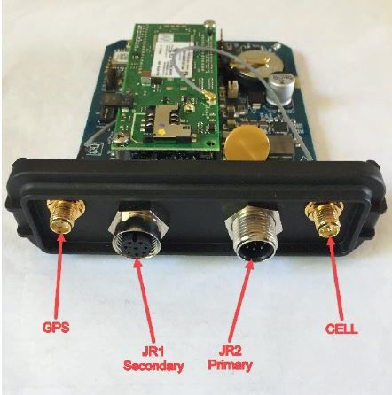
Messenger BLE
        User Manual

        9     Configuration ..................................................................................................................................................... 31
               9.1      Debug Configuration Commands .......................................................................................................... 33
                          9.1.1 Read Command........................................................................................................................ 33
                          9.1.2 Reset Command ....................................................................................................................... 34
                          9.1.3 Global Command ...................................................................................................................... 34
               9.2      OTA Configuration Commands ............................................................................................................. 35
                          9.2.1 OTA Command ......................................................................................................................... 35
                          9.2.2 SMS Command ........................................................................................................................ 35
               9.3      Site Configuration – Type 1 ................................................................................................................... 36
               9.4      Options Configuration – Type 2 ............................................................................................................. 38
               9.5      CELL Configuration – Type 3 ................................................................................................................ 39
               9.6      FTP Configuration – Type 4................................................................................................................... 41
               9.7      Geofence Configuration – Type 5 .......................................................................................................... 42
               9.8      Serial Port Configuration – Type 6 ........................................................................................................ 43
               9.9      Reporting Configuration – Type 7 .......................................................................................................... 45
               9.10 Engine Configuration – Type 8 .............................................................................................................. 47
               9.11 Channel Configuration – Type 9 ............................................................................................................ 49
               9.12 Report Flag Configuration – Type 12 .................................................................................................... 53
               9.13 Date/Time Read/Write – Type 16 .......................................................................................................... 55
               9.14 MODBUS Configuration – Type 18 ....................................................................................................... 56
               9.15 Analog Input Configuration – Type 11 ................................................................................................... 59
               9.16 Digital Input Configuration – Type 17 .................................................................................................... 60
               9.17 Digital Output Configuration – Type 13 ................................................................................................. 61
               9.18 EVAL Expression Configuration – Type 10 ........................................................................................... 62
               9.19 J1939 PGN Configuration – Type 15 ..................................................................................................... 65
               9.20 J1939 SPN Configuration – Type 14 ..................................................................................................... 66
               9.21 PEER Poll Configuration – Type 28 ...................................................................................................... 68
               9.22 PEER Push Configuration – Type 29 .................................................................................................... 69
               9.23 Bluetooth Nordic Configuration – Type 52............................................................................................. 70
        10 How-To .............................................................................................................................................................. 71
               10.1 Setting Reporting Rates When Moving and Stationary ......................................................................... 71
               10.2 Computing Engine Hours from Engine Run .......................................................................................... 71
               10.3 Enabling Low Power Mode to Conserve Battery ................................................................................... 71
               10.4 Setting Hard Acceleration/Deceleration Alarms .................................................................................... 72

                                                                                          4

9M02-7000-A101-EN
Version A
Messenger BLE
        User Manual

               10.5 Using a Digital Input to Determine Engine On ....................................................................................... 72
               10.6 Using the Analog Input for Fuel Level ................................................................................................... 73
        11 Appendix A – Monitored Engine Parameters .................................................................................................... 74
        12 Appendix B – Data Registers ............................................................................................................................ 77
        13 Technical Support ............................................................................................................................................. 88

                                                                                       5

9M02-7000-A101-EN
Version A
Messenger BLE
        User Manual

        Introduction
        This User Manual describes installation and setup of the Messenger-BLE product. Throughout this document,
        Messenger-BLE and Messenger are used interchangeably.
        The Messenger is a complete monitoring, alarm notification and telemetry platform. The intended markets
        include, but are not limited to, water/waste water utility, off-road heavy construction equipment, on-road semi-
        trucks, oil and gas, and standby power generators. It supports monitoring of data values from on-board physical
        IO, the J1939 SAE engine bus topology and the industry standard Modbus RTU serial protocol, as well as
        support of custom serial communications to external devices.
        Features
        The hardware feature set of this platform includes the following:
            •   ARM 32-bit Cortex -M4 Core w/FPU
            •   2 MB of on-board FLASH memory, 8 MB of external FLASH
            •   640 KB of on-board SRAM memory, 512 KB of external battery-backed SRAM
            •   Real Time Clock (battery-backed)
            •   Two Serial Ports (RS485 only)
            •   Four Digital Inputs (user configurable for voltage or grounded input)
            •   Three Digital Outputs (open-collector transistor closures to ground)
            •   Three Analog Inputs (12-bit, user configurable for V or I input)
            •   One CAN Interface, compliant to Bosch CAN Protocol v2.0 A/B
            •   Cellular modem: HSPA (3G) or LTE (4G)
            •   GPS receiver, providing location services using multiple GNSS constellations
            •   3-axis Accelerometer
            •   SuperCap for brown-out protection
            •   Separate Bluetooth engine for wireless connection to hand-held devices
            •   Deutsch EEC automotive grade enclosure

                                                                6

9M02-7000-A101-EN
Version A
Messenger BLE
User Manual
1 Description
1.1 Capabilities
The Messenger is a highly configurable platform for remote monitoring and control applications. Some of the
capabilities are listed below.
• Virtual real-time transfer of monitored conditions
• Local computations from monitored conditions
• Time stamping of monitored data and events
• Battery-backed historical data/event buffers
• Automatic monitoring of max/min for analog values
• Continuous monitoring of J1939 bus data
• Event and data logging
• Telemetry of monitored conditions to server applications via cellular
• Over the Air (OTA) programming and diagnostics, cellular and Bluetooth
• SMS messages sent on monitored conditions
• Parameter setting via SMS messages
1.2 Monitoring
All monitored values can be transmitted via cellular to a host server of the customer’s choosing. Monitored
values are transmitted based on time or notification events. Notification events are based on rules set by the
user and each event can generate an immediate report. Telemetry includes cellular connectivity and GPS for
asset location.
Monitored data values are mapped to fixed channels in the Messenger. A channel defines a set of attributes for
the monitored data for doing calculations, alarm detection, data formatting and reporting.
For example, RPM is fixed to channel 52. For channel 52, the user can set limits on RPM for notification when
the RPM gets too high, and how to report the RPM values to a host server.
See Table 7 for a description of all the predefined channels and channel numbers. Appendix A – Monitored Engine
Parameters is used to identify the set of SAE defined PGNs and SPNs for data values being read from the engine
bus. The user can also configure for other engine values as needed.
1.3 Host Server Communications
The Messenger utilizes a proprietary protocol to send notifications and to receive OTA commands from a host
server. Each notification sent typically consists of location, date/time, an event code and associated data. An
event code provides a unique identifier to indicate the reason that the notification is being sent – for example,
normal scheduled update or an engine diagnostic message received. A description of the protocol, format of
messages and definition of event codes is available on request; contact Cattron at www.cattron.com/contact for
additional information (reference the protocol document “M09-PRTCLxxx”).
Some of the conditions on which notifications can be sent to the host server are listed below:
• Any monitored value exceeding a predefined or user-defined limit
• Any diagnostic message received from the engine bus
• Digital input changing state (on/off)
• Digital output changing state (on/off)
7
9M02-7000-A101-EN
Version AMessenger BLE
User Manual
• Analog input transitioning into a warning or alarm region
• Analog input changing by user defined delta
• Scheduled/periodic update
• End of day
• System faults
• SMS text commands from a user or host server
• Power on or reset
1.3.1 Event Codes
Every message sent by the Messenger to a host-based server application is triggered by an event. The event
generates a message and the message contains an Event Code. The Event Code uniquely identifies to the
server the reason the message is being sent. Some of the messages generated contain data, others serve as
just notification that a particular event has occurred. Protocol document “M09-PRTCLxxx” contains a list of all
event codes.
1.3.2 Positive Acknowledgement
The Messenger can be configured to require a message acknowledgement from the host server or to send
once and forget. Message acknowledgement provides a verifiable mechanism that a message was delivered,
even during poor network conditions.
This parameter setting can be found in the CELL Configuration – Type 3 section.
1.3.3 Store and Forward Data Queue
There are several scenarios where a message may not be deliverable – network down, host server down
and poor connectivity, to name a few. In the event that a message cannot be delivered, it is stored in
memory and is continually re-sent until it is properly acknowledged. This store and forward memory is non-
volatile and remains intact during power off.
1.3.4 Real-Time Clock (RTC)
The RTC is used to timestamp data records and events. All messages sent to the host server contain a
timestamp to provide a chronology of data/events to the end user. This timestamp is UTC time. All timestamps
viewed from the debug menu are local time based on the configured time zone.
The RTC is battery-backed to provide time keeping during power off. If the RTC is configured to be
automatically set, the Messenger will set the time after every power on and perform a time check every
midnight. If the RTC time differs from the actual time by more than 30 seconds, the RTC time will be adjusted.
The RTC can be set in one of the following ways:
Method Description
This is the default setting. The Messenger will set the RTC from an internet NIST time
Automatic via Cell
server.
Automatic via GPS The Messenger will set the RTC from the date/time read from the GPS module.
Manually The time is set via the Debug port through the Maintenance menu.
OTA/SMS The RTC is set from an OTA config command or an SMS config command.
8
9M02-7000-A101-EN
Version AMessenger BLE
User Manual
Configuration settings are available to define how the RTC is set.
1.3.5 Packaging
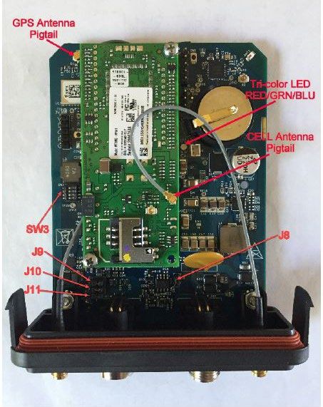
The Messenger is packaged in an automotive grade Deutsch enclosure. There are two antenna connections, one
SMA connection for the GPS and one SMA-RP (reverse polarity) connection for cellular. The enclosure end-cap
provides two circular M12, 8-pin connectors for power and IO. Figure 1 shows the interior of the Messenger BLE
with the enclosure end-cap attached.
Figure 1: Messenger with Enclosure End-Cap Attached
1.3.6 Specifications
Power input: 8-36 VDC
26 mA @ 24 VDC (avg)
Reverse polarity protection
Overvoltage protection
Internal solid-state fuse
Digital outputs (3 each): Open-collector transistor switch to ground (current sink)
500 mA @ 12 VDC
Current limited
Overvoltage protection
9
9M02-7000-A101-EN
Version AMessenger BLE
User Manual
Digital inputs (4 each): Two modes of operation: DC voltage input or grounded input (user
selectable)
High-speed pulse counter inputs (user selectable)
Current limited
Overvoltage protection
Analog inputs (3 each): 12-bit ADC
Accuracy: +/- 2% FS
Input ranges: 0-10 VDC, 0-20 mA, 4-20 mA (user selectable)
CAN input (1 each): Termination resistor (user selectable)
Spike suppression
Serial RS485 inputs (2 each): Termination resistor (user selectable)
Current limited
Overvoltage protection
Bluetooth (1 each): Internal chip antenna (external antenna available; contact Cattron at
www.cattron.com/contact for additional information)
Application available for hand-held devices
Operating Temperature
-40 to +85 °C
Range:
10
9M02-7000-A101-EN
Version AMessenger BLE
User Manual
2 Installation and Setup
This section provides information on installing the Messenger and confirming its initial operation.
WARNING
! IT IS RECOMMENDED THAT YOU READ THIS ENTIRE CHAPTER BEFORE STARTING THE
INSTALLATION.
2.1 Installation Steps
Installation consists of the following steps:
1. Unpack the Equipment.
2. Mount the Equipment.
The Messenger should be mounted in a vertical position to try and minimize the chance of water entering
through the antenna connections. The antenna wires should have a service loop just below the antenna
connectors.
3. Connect Main Power.
4. Connect to engine bus – J1939.
5. Confirm that the Amber LED indicates normal CAN activity when the engine is started. If it does not, check
the following:
a. Confirm there is proper termination on the main CAN bus trunk.
b. Double check the bus connections and signal polarity.
2.2 Unpacking the Equipment
The Messenger is shipped with the following:
• The Messenger electronics housed in a Deutsch thermoplastic enclosure
• A Cellular/GPS dual antenna (magnetic mount or bulkhead screw mount)
• User Manual (available electronically)
• Cable harnesses providing access to all Messenger IO
2.3 Mounting the Equipment
The Messenger is housed in an automotive grade weather resistant enclosure; the dimensions of the enclosure
are shown in Figure 2. The entire enclosure with mated connectors is rated to IP55.
CAUTION
! MOUNT THE ENCLOSURE IN A VERTICAL ORIENTATION AND PROVIDE SERVICE LOOPS FOR
EACH ANTENNA AND IO CABLE TO PREVENT WATER INTRUSION.
11
9M02-7000-A101-EN
Version AMessenger BLE
User Manual
2.3.1 EEC Thermoplastic Enclosure
Figure 2: Deutsch EEC Thermoplastic Enclosure Dimensions
When mounting the enclosure to vibrating equipment, it is recommended that you use rubber dampeners to
isolate the unit. Stainless mounting hardware is preferred and the use of lock washers is highly recommended.
2.4 Mounting the Antenna
The antenna shipped with the Messenger is a hockey puck style, a combination of cell and GPS. The GPS
antenna frequency is 1575.42 MHz. The cell is a dual band antenna: 880-960 MHz and 1710-1990 MHz. The
antenna can be ordered with a magnetic or a screw mount base.
In general, the antenna should be mounted with an unobstructed view of the sky. The GPS side works best when
it can see the horizon. If the antenna is mounted outside and may be subject to lightning, a surge arrestor can be
inserted between the Messenger antenna SMA connection and the antenna. If the antenna is mounted inside, it
should be located near a window.
CAUTION
! SERVICE LOOPS SHOULD BE PROVIDED FOR THE ANTENNA CABLING, NEAR THE ANTENNA
CONNECTIONS, IN ORDER TO MINIMIZE WATER INGRESS THROUGH THE SMA RF COAX
CONNECTIONS.
12
9M02-7000-A101-EN
Version AMessenger BLE
User Manual
2.5 DIP Switch/Jumper Settings
The Messenger uses an on-board DIP switch and jumpers to configure application specific IO and set operational
modes. DIP SW3 is used to set operational modes. See Figure 3 for switch and jumper locations. See Figure 4 for
IO selection settings.
Figure 3: Messenger IO Connectors
13
9M02-7000-A101-EN
Version AMessenger BLE
User Manual
Figure 4: Messenger IO Signals
2.6 DIP Switch 3 Decode
DIP Switch 3 is a 4-position dip switch located on the left side of the board (refer back to Figure 1 to see the
location). If any position on switch 3 is changed, the power must be cycled for the new switch positions to be read.
Table 1 describes the position of the dip switches.
14
9M02-7000-A101-EN
Version AMessenger BLE
User Manual
Table 1: DIP Switch 3 Decode
Position 1 2 3 4 Description
Function
Used for code download via internal debug port - RS232,
Enter BOOT Loader
57600,8,1,N
Factory Default Settings
Key: = switch in “OFF” position, = switch in “ON” position
Note: Switch positions 1 and 2 will override any other settings for Ports 2, 3, or 4.
2.7 IO Connections
The Deutsch EEC enclosure has a watertight end-cap fitted with one M12x8 MALE connector (JR2-PRI), one
M12x8 FEMALE connector (JR1-SEC), one SMA JACK GPS antenna connector, and one SMA-RP JACK CELL
antenna connector, as previously shown in Figure 3.
Depending on the customer input/output requirements, there may be one or two cable harnesses supplied for the
customer to connect to his field signals. The IO signals available in the Messenger are diagrammed as shown in
Figure 4, which indicates how to connect field signals to the Messenger using these cables. Custom cable
configurations can be made to facilitate field wiring. Contact Cattron at www.cattron.com/contact for assistance.
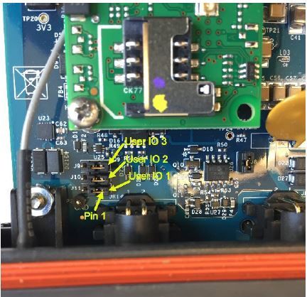
There are three IO signals that are user definable via on-board jumpers. The options for these user IO signals are
shown in Table 2, Table 3 and Table 4. Their locations are shown in Figure 5.
Table 2: User IO 1 Jumper Selection – J11
User IO 1 J11
DOUT 1 1-2
P2-RS485A 2-3
Table 3: User IO 2 Jumper Selection – J10
User IO 2 J10
DOUT 2 1-2
P2-RS485B 2-3
Table 4: User IO 3 Jumper Selection – J9
User IO 3 J9
DOUT 3 1-2
AIN3 2-3
15
9M02-7000-A101-EN
Version AMessenger BLE
User Manual
Figure 5: User IO Jumper Location
2.8 Cellular Setup
The Messenger supports two cellular technologies, HSPA (3G) and LTE (4G). The current offering for HSPA is a
3G penta-band capable radio. For LTE, it is a 4G, dual-band radio. Both of these radio options require a wireless
account with a cellular provider such as AT&T or Verizon. The requirements for each option are shown in Table 5.
Table 5: Cellular Modem Requirements
Provider Account Username/
Radio Static IP SIM APN Server IP/Port
Options Type Password
AT&T Data+
HSPA (3G) required required required optional required
Verizon SMS
AT&T Data+
LTE (4G) required required required optional required
Verizon SMS
2.9 Bluetooth Setup
The Messenger uses a dedicated processor for facilitating Bluetooth Low Energy (BLE) connections. The
hardware offers two antenna options: a chip antenna enabled by default and requiring no further hardware, and a
U.FL connector for connecting external antennas for the potential of greater RF performance.
16
9M02-7000-A101-EN
Version AMessenger BLE
User Manual
3 LED States
There is one tri-color LED visible to the user to indicate various system conditions, whose location is shown in
Figure 6: Status LED Location. These conditions are conveyed to the user via LED color and blink patterns. Blinking of
LEDs can be disabled via a configuration setting (see the Options Configuration – Type 2 section). On power-up, an
LED test is performed by blinking all LEDs every second for 3 seconds. Following the LED test, the LEDs blink
based on the conditions described below.
The number of blinks will range from one to three. The general philosophy when deciding behavior will be as
follows:
• One blink will convey a state that the module is expected to be in most often (the “OK” state)
• Three blinks are used to convey that there is an issue that may need attention
• Two blinks are used as needed to convey a state that may be of interest to the user
• No blinks (LED solid on or off) indicates that the system is no longer functioning (first verify that the option
to turn the LED off is disabled, and then contact Cattron at www.cattron.com/contact for assistance)
Status LED Behavior
The Status LED will cycle through blinking each color for the appropriate number of times to convey the state of
the corresponding module, as shown in Table 6. There is a pause between color changes.
Table 6: LED Color/Blink Patterns
Module Color 1 Blink 2 Blinks 3 Blinks
Power fail
Power Green Power OK ----
(On Supercap)
Data Queue Not Fault / Failed to
Cell Red Data Queue Empty
Empty initialize modem
Device Not advertising /
Bluetooth Blue Advertising On
Connected No comms to nRF
CAN Amber CAN OK ---- No CAN
Figure 6: Status LED Location
17
9M02-7000-A101-EN
Version AMessenger BLE
User Manual
4 IO Architecture
The IO architecture is shown in Figure 7. Each of the physical IO entities has a configuration that is set based on
user requirements. Based on that configuration, the values sampled are stored in their respective data registers.
These data registers are used to reference the corresponding value for use in channel creation or in expressions
used to compute values. The complete list of available data registers can be found in Appendix B – Data Registers.
Figure 7: IO Architecture Diagram
18
9M02-7000-A101-EN
Version AMessenger BLE
User Manual
5 Channels
The Messenger maps all monitored conditions into channels. Each channel has data storage and configuration
parameters. Data storage holds current value, max/min values, and other run time data values. Configuration
consists of user settable parameters that define rules on how the data values are to be processed (see the
Channel Configuration – Type 9 section).
The data stored in a channel is user definable. In the channel configuration, the user can set the “source” of the
data from a set of data registers. These data registers span all the possible IO in the system, i.e., CAN,
MODBUS, physical, computed, etc. The complete list of available data registers can be found in Appendix B – Data
Registers.
Every channel in the Messenger is referenced by a fixed channel number; for example, RPM is always channel
52. There is a set of predefined channels (numbers 1-300) and a set of user-defined channels (numbers 301-
350). The user-defined channels can be configured to represent any data value in the system. The predefined
channels have the data source parameter already set.
5.1 Predefined Channels
The channels outlined in Table 7 are predefined in the Messenger:
Table 7: Predefined Channels
Channel Channel Name Type Source Data Description
Number Register
Start Digital Channels (data values are ‘0’ or ‘1’)
1 Cell Digital Internal Status of cellular modem operation
(System) 1=fault
0=normal
2 Comm Digital Internal Status of any serial port used for
(System) communications with external device
(MODBUS Master, Slave, or
proprietary)
1=fault
0=normal
3 J1939 Digital Internal Status of communications with
(System) engine bus (J1939)
1=fault
0=normal
4 User DIN1 Digital If SWX4-1 closed:
0=open
1=ground applied
If SWX4-1 open:
1=open
0=voltage applied
19
9M02-7000-A101-EN
Version AMessenger BLE
User Manual
Channel Channel Name Type Source Data Description
Number Register
21 User DIN2 Digital If SWX4-2 closed:
0=input open
1=input grounded
If SWX4-2 open:
1=input open
0=voltage > 3 VDC
5 User DIN3 Digital If SWX4-3 closed:
0=input open
1=input voltage < 1 VDC
If SWX4-3 open:
1=input open
0=input voltage > 3 VDC
6 User DIN4 Digital If SWX4-4 closed:
0=input open
1=input voltage < 1 VDC
If SWX4-4 open:
1=input open
0=input voltage > 3 VDC
9 Engine Run Digital Engine run state
1=on
0=off
(run if RPM > start threshold)
10 Shutdown Digital CAN/J1587 Red LED
Engine Shutdown Indicator
11 Warning Digital CAN/J1587 Amber LED
Check Engine Indicator
20 GPS Digital Status of GPS
(System) 1=fault
0=normal
30 User DOUT1 Digital State of digital output 1
0=not energized
1=energized
31 User DOUT2 Digital State of digital output 2
0=not energized
1=energized
32-39 Spare Digital Undefined
40 DPF Passive Regeneration Digital Support for tier 4 diesel engines
Status
20
9M02-7000-A101-EN
Version AMessenger BLE
User Manual
Channel Channel Name Type Source Data Description
Number Register
41 DPF Active Regeneration Digital Support for tier 4 diesel engines
Status
42 DPF Active Regeneration Digital Support for tier 4 diesel engines
Inhibit Status
43 DPF Active Regeneration Digital Support for tier 4 diesel engines
Inhibit Switch
44 DPF Active Regeneration Digital Support for tier 4 diesel engines
Inhibit Temp Lockout
45 DPF Active Regeneration Digital Support for tier 4 diesel engines
Inhibit Perm Lockout
46 DPF AutoAct Regeneration Digital Support for tier 4 diesel engines
Config
47 DPF1 Cond Not Met For Digital Support for tier 4 diesel engines
Regeneration
48-50 Spare Digital Undefined
Start Analog Channels (data values are floating point, precision is user configurable)
51 Fuel Level Analog Fuel Level, 0-100%
52 Eng RPM Analog Engine speed, RPM
53 Eng HRS Analog Accumulated engine run time (hours)
56 Coolant Temp Analog In degrees C
57 Battery Analog Volts reading
58 Electrical Analog Volts reading
59 Oil Pressure Analog Oil pressure in psi
60 Fuel Rate Analog In gallons per second
62 User Analog Analog On-board analog input, 10-bit ADC
can be configured for 0-1, 0-5, 0-10
VDC, or 0-20 mA
79 Vehicle Distance Analog Total distance vehicle has travelled,
odometer
81 Engine Starts Analog Accumulated count of engine starts
82 Idle Time Analog Accumulated time the engine RPM
has been between the Engine Start
Threshold and Idle Threshold
(seconds) since last start
83 Idle Fuel Analog Accumulated fuel used during Idle Time
(gallons)
21
9M02-7000-A101-EN
Version AMessenger BLE
User Manual
Channel Channel Name Type Source Data Description
Number Register
84 Work Time Analog Accumulated time the engine RPM has
been above the Idle Threshold
(seconds) since last start
85 Work Fuel Analog Accumulated fuel used during Work
Time (gallons)
86 Daily Idle Time Analog Accumulated Idle Time for the day
87 Daily Idle Fuel Analog Accumulated Idle Fuel for the day
88 Daily Work Time Analog Accumulated Work Time for the day
89 Daily Work Fuel Analog Accumulated Work Fuel for the day
90 Oil Level Analog In percent
91 Oil Temp Analog In degrees F
92 Coolant Level Analog In percent
95 Throttle Position Analog In percent
96 Road Speed Analog In MPH
105 Barometric Pressure Analog Ambient pressure in psi
106 Cabin Temperature Analog In degrees F
107 Ambient Temperature Analog In degrees F
108 Accelerator Pedal Position Analog In percent
109 Air Filter Diff. Pressure Analog In psi
110 Engine Load Analog In percent
111 Engine Torque Analog In percent
118 Daily Distance Traveled Derived Accumulated distance travelled for the
day
119 Daily Fuel Used Derived Accumulated fuel used for the day
120 Trip Distance Traveled Derived Accumulated distance travelled for last
trip (trip defined as engine on to engine
off)
121 Trip Fuel Used Derived Accumulated fuel used for last trip (trip
defined as engine on to engine off)
151 Engine Fuel Temp Analog In degrees F
152 Estimated Fan Speed Analog In percent
153 Transmission Oil Temp Analog In degrees F
154 Daily Flow Volume Derived Accumulated flow volume for the day
(flow rate from ADC input)
155 Running Flow Volume Derived Accumulated flow volume since last
volume reset (flow rate from ADC input)
22
9M02-7000-A101-EN
Version AMessenger BLE
User Manual
Channel Channel Name Type Source Data Description
Number Register
250 Generator, Total kW Hours Analog In KWh
Export
Channels specific to Generators are available on Request Only
251 Generator, Total Reactive Analog In KVAR
Power
252 Generator, Overall Power Analog
Factor
253 Generator, Total Real Analog In kW
Power
254 Generator, Average Analog In V
Line-Line AC RMS Voltage
255 Generator, Average Line- Analog In V
Neutral AC RMS Voltage
256 Generator, Average AC Analog In Hz
Frequency
257 Generator, Average AC Analog In A
RMS Current
258-259 Spare Undefined
260 DPF1 Soot Load Analog Support for tier 4 diesel engines
261 DPF1 Ash Load Analog Support for tier 4 diesel engines
262 DPF1 ET Regen Analog Support for tier 4 diesel engines
263 AT1 DPF Regen Threshold Analog Support for tier 4 diesel engines
264 DPF2 Soot Load Analog Support for tier 4 diesel engines
265 DPF2 Ash Load Analog Support for tier 4 diesel engines
266 DPF2 ET Regen Analog Support for tier 4 diesel engines
267 AT2 DPF Regen Threshold Analog Support for tier 4 diesel engines
268 DPF Lamp Cmd Analog Support for tier 4 diesel engines
269 DPF Status Analog Support for tier 4 diesel engines
270 Exh High Temp Lamp Cmd Analog Support for tier 4 diesel engines
271 Eng Trip Fuel Analog Support for tier 4 diesel engines
272 Eng Total Fuel Analog Support for tier 4 diesel engines
273 AT1 Def Tank Level 1 Analog Support for tier 4 diesel engines
274 AT1 Def Tank Level 2 Analog Support for tier 4 diesel engines
275 AT Cat Reduction Active Analog Support for tier 4 diesel engines
276 Eng Wait Start Lamp Analog Support for tier 4 diesel engines
23
9M02-7000-A101-EN
Version AMessenger BLE
User Manual
Channel Channel Name Type Source Data Description
Number Register
277 Eng Protect Shutdown Analog Support for tier 4 diesel engines
278 Eng Protect Near Shutdown Analog Support for tier 4 diesel engines
279 Eng Protect Cool Level Analog Support for tier 4 diesel engines
Status
290-300 Spare
Start User-Defined Analog Channels
301-350 User-Defined User Analog or Digital channels
Defined
5.2 Channel Data
All values read from physical IO, an engine bus or from a Modbus slave device are continually updated and tested
as defined by the configuration parameters. For each channel, based on its type (analog or digital), there is a
basic set of data collected. For purposes of discussion, the term “not normal” is used to indicate an analog value
that has violated a limit threshold or a digital value that does not match its configured ‘normal’ state.
Basic Data Set -
For the analog channels:
• Current value
• Max/min values (daily)
For the digital channels:
• Current value
• Previous value
• Count of transitions to not normal (in counts)
• Accumulated time in not normal state (in seconds)
There are a few channels that can be configured for special functions. All the physical digital input channels can
be configured to accept pulse inputs (e.g., from a flow meter) and the physical analog inputs can be used to
totalize volume when the input is a flow rate. These channels have an extended data set.
Extended Data Set -
For the analog channels:
• Daily total volume (available on channel 154)
• Continuous running total volume (available on channel 155)
For the digital channels:
• Flow rate
• Daily total volume
• Continuous running total volume
24
9M02-7000-A101-EN
Version AMessenger BLE
User Manual
The Messenger also maintains two other complete sets of channel data – trip data and daily data.
A trip is defined as the time from engine start to engine stop, independent of distance traveled. During that time, a
separate set of current and max/min values are maintained. At engine stop, an end of trip report is generated from
this data.
The daily data set is a separate set of current and max/min values that span the 24 hour period from midnight to
midnight, UTC time. At midnight, an end of day report is generated from this data.
Because Modbus channel data is polled, Modbus digital channels do not maintain count or duration values.
25
9M02-7000-A101-EN
Version AMessenger BLE
User Manual
6 SMS Text Commands
The Messenger can receive and execute SMS commands to perform specific functions. The SMS command set
includes the following:
• ADIPREQ – request to connect to remote diagnostic utility
• ACTION – on-demand action request
6.1 Command Syntax
The commands can be upper case, lower case or a combination, as illustrated here:
• - request sent to Messenger to connect to remote diagnostic utility; contact
Cattron at www.cattron.com/contact for assistance
ip = IP address of PC that the diagnostic utility is running on
port = port number on the PC that the IP address is bound to
s = spare (leave blank)
• - request to execute action identified by action number
x = action number, as defined in Table 8
Table 8: Action Commands
Action Number Action Description Response
1 Generate on-demand standard report to host server ack+ report
2 Return status to sender status
3 Force cell modem reset ack
4 Clear all stored data records ack
5 Return Cell config to sender cell config
6 Force digital output 1 on ack
7 Force digital output 1 off ack
8 Generate on-demand end of day report to host server ack+ report
9 Return current GPS coordinates to sender coordinates
10 Return a subset of channel data values to sender data values
(Channels are fixed and include RPM, Engine Hours, Coolant
Temp, Battery Voltage, Oil Pressure and Odometer)
13 Clear oldest data record from queue ack
16 Force digital output 2 on ack
17 Force digital output 2 off ack
24 Reset/restart Peer poll/push ack
26 Force exit of mini-ping mode ack
28 Zero all non-volatile counter data ack
30 Return SIM card info SIM info
26
9M02-7000-A101-EN
Version AMessenger BLE
User Manual
Action Number Action Description Response
32 Clear ADC channel daily flow totals ack
33 Clear ADC channel running flow totals ack
35 Return CELL Status CELL status
40-43 OEM Specific
50-55 Initiate Modbus control sequence
99 Force Hardware Reset ack
Action Responses:
ack text:
v: r: c
status text:
VID(v)-CELL(i s)-REG(r g)-RSSI(#)-GPS(p)-JBUS(j m n)-DATAQ(d e f)-OUTP(a b)-SWX(x)-MSGS(f c)-
VER(v#.#.# date prot modem jbus)
VID: v = vehicle ID
CELL: i = init state
s = current state
REG: r = tower registration
g = data registration
RSSI: # = signal strength
GPS: p = 1 for fix, 0 for no fix
JBUS: j = J1939
m
n
DATAG: d = count in queue
e = deleted from queue
f = failed
OUTP: A
B
SWX
MSGS: f = failed
c = count
VER: prot = protocol (Antx, Rastrac, other)
modem = type of modem
27
9M02-7000-A101-EN
Version AMessenger BLE
User Manual
jbus = type of bus
coordinates text:
VID(v)-LAT(s)-LON(g)-STATUS(u)-AGE(p)-ANT(j)
SIM info text:
VID(v)-MSISDN(s)-ICCID(g)-IMSI(u)-IMEI(p)
data text:
VID v-Running: s-52 RPM: r-x Hours: h- CoolTemp: x-Battery -OilPress -Odometer o
28
9M02-7000-A101-EN
Version AMessenger BLE
User Manual
7 Modbus
The Messenger can be configured as a Modbus Master, Modbus Slave or both. This is done by setting the Mode
of one of the available user serial ports, 5 or 6. Both ports support RS485 only. If RS232 is required, an RS485 to
RS232 adapter will need to be inserted.
7.1 RTU Slave
Being configured as a Modbus RTU Slave device allows SCADA/HMI software to read channel values from the
Messenger. Setting up a serial port is the only configuration necessary to enable Modbus Slave operation.
Also available is writing values to the Messenger from a MODBUS Master. These written values can then be
transferred to a channel for alarming or logging for telemetry.
The Modbus register map for all channel data values is available on request; contact Cattron at
www.cattron.com/contact for additional information and reference the document “MessengerBLE MODBUS
Slave”.
7.2 RTU Master
When configured as a Modbus RTU Master device, the Messenger reads register values from Modbus Slave
devices.
In addition to setting up a Modbus Master serial port, the MODBUS data registers in the Messenger must be
configured to receive the values read from the slave device. As shown in the Channel Configuration – Type 9
section, define the Modbus Slave address, the register data type to read, the register number, how to interpret or
scale the data being read, and any alarm limits.
29
9M02-7000-A101-EN
Version AMessenger BLE
User Manual
8 Debug Menu
The debug menu is a text based menu system accessible via terminal emulation software running on a PC
(such as Tera Term or HyperTerminal) or via a PC based utility that connects to the Messenger OTA via TCP.
Debug menus allow the user to view or change configuration parameters, view data values and history logs, see
communications between CPU and attached peripherals, and to clear accumulated data values or logs.
The Debug Menu can be accessed via a direct serial RS232 connection to Port 2, Port 3 or Port 4, or via an
over the air connection using the ADIP remote diagnostic utility. This utility is available on request; contact
Cattron at www.cattron.com/contact for additional information. DIP Switch 3, as described in Table 1, can be
used to force a direct connect serial port into Debug mode.
Note: Once connected, press the ‘Enter’ key to see the Main Menu (example below).
Messenger : ANTX G2 J1939
Version : v6.4.2 A 09/26/15
Date/Time : 11/10/15 14:24:03
Asset ID : 011998000279820
MSISDN : 15332791849
Local IP : 10.115.17.6
CELL RSSI : 13 (13,12)
GPS : Fix Ok
QueDepth : 0
Output 1 : Off
Output 2 : Off
1) View Config
2) Timers
3) Data
4) Events
5) Reports
6) Setup
7) Maint
8) J1939 Diags
Cmd =>
Most menu navigation commands are single alpha-numeric entries, no carriage return (Enter) required. However,
when modifying configuration parameters, the configuration string entered must be followed by a carriage return
(Enter).
30
9M02-7000-A101-EN
Version AMessenger BLE
User Manual
9 Configuration
The Messenger is a highly configurable platform with several methods in place to allow a user to read and/or
modify the whole configuration or any part of it. All configuration parameters are stored in non-volatile memory.
Configuration parameters can be changed using the following methods:
• User modify via debug menu, using direct RS232 serial
• User modify via debug menu, using remote diagnostic utility
• Transfer configuration file, using XMODEM-1K over direct RS232
• Transfer configuration file via remote diagnostic utility
• Transfer configuration file via FTP
• User read/modify via SMS text message
All configuration parameters are read/written using text strings, with commas to separate values in the string. This
basic format is the same for all of the methods listed above. Some of the methods put a “wrapper” around the
configuration line to aid in transport and decoding on the receiving end.
The basic configuration line (CL) format is described below:
CL = x,y,zzzz,y,zzzz,y,zzzz,…,y,zzzz
where:
• The commas are required as the delimiter between value fields
• x is a unique number identifying the configuration line type (e.g., Site=1, Serial=6, Channel=9, etc.)
• is an optional index used with specific configuration line types that have more than one element (e.g.,
there is more than one Serial Port and more than one Channel)
• y is a parameter code identifying the configuration parameter that follows
• zzzz is the configuration parameter (this parameter could be an integer, a floating point number or a text
string, as defined by the parameter code y)
Table 9 identifies the available configuration line types and their type code.
Table 9: Configuration Line Types
Type Reference Description Optional Index
Code
1 Site Messenger global settings None
2 Options System Options settings None
3 Cellular Cellular communication settings None
4 FTP FTP settings None
5 Geofence Geofence definitions Geofence Number
Range 1-10
6 Ports Serial port parameters Serial Port Number
Range 1-6
7 Reports Defines how/when updates are sent to the None
host server
8 Engine J1939/J1708/OBDII parameters/settings None
31
9M02-7000-A101-EN
Version AMessenger BLE
User Manual
Type Reference Description Optional Index
Code
9 Channels Set scaling and alarm parameters for Channel Number
channels Range 1-400
10 Expressions Mathematical expressions Expression Index
Range 1-10
11 Analog Inputs Physical analog inputs ADC input
Range 1-6
12 Report Flags Defines data types to include in reports to Channel Number
the host server Range 1-400
13 Digital Outputs Physical digital outputs Digital Output
Range 1-3
14 J1939 SPN Parameters specific to PGNs on a J1939 SPN Index
bus Range 1-XX
15 J1939 PGN Parameters specific to PGNs on a J1939 PGN Index
bus Range 1-XX
16 Date/Time Set Date/Time manually None
17 Digital Inputs Physical digital inputs Digital Input
Range 1-4
18 MODBUS MODBUS Poll Parameters MODBUS Index
Range 1-100
20 Engine Control Access to panel engine control parameters None
25 MODBUS Control MODBUS Control Sequence Definition Sequence Number
Sequence Range 1-6
28 Peer Poll Peer Index
Range 1-16
29 Peer Push Peer Index
Range 1-16
30 VFD VFD Parameter Setup None
40 Virtual Channel Virtual channel configuration parameters Virtual Channel Index
Range 1-40
96 FOTA FOTA configuration for updating cellular None
modem firmware
32
9M02-7000-A101-EN
Version AMessenger BLE
User Manual
9.1 Debug Configuration Commands
Users can manage the current configuration via the built-in Debug Menu system. From the main menu, select Site
Setup (6). From Site Setup, select User Input (1). From the User Input prompt, the following read/modify
commands are applicable.
9.1.1 Read Command
This is the read configuration command format:
255,x
where:
• 255 is the read command
• x is the configuration line type code
• is an optional index that is a function of the line type code (see Table 9 in Section 9)
• is a line terminating carriage return
Some examples using the READ command:
Examples:
255,1 Prints Site config
255,8 Prints Engine config
255,6,1 Prints Serial Port 1 config
255,6,255 Prints all Serial Port configs
255,255 Prints a Full System config
By issuing the “255,255” command, the user can capture a complete system configuration to a file. This file can
then be used as the master configuration file. This master config file can then be modified and loaded back into
the system or any configuration segment that needs updating.
Some examples using the READ command via SMS:
Examples:
Returns Site config
Returns Engine config
Returns Serial Port 1 config
Invalid SMS Read command
Invalid SMS Read command
CAUTION
! THE READ ALL COMMAND (255,255) DOES NOT FUNCTION VIA SMS DUE TO SMS MESSAGE
SIZE CONSTRAINTS.
33
9M02-7000-A101-EN
Version AMessenger BLE
User Manual
9.1.2 Reset Command
To reset a configuration to factory defaults, use the following command format:
256,x
where:
• 256 is the reset command
• x is the configuration line type code
• is an optional index that is a function of the line type code (see Table 9 in Section 9)
• is a line terminating carriage return
Some examples using the RESET command:
Examples:
256,1 Reset Site config
256,8 Reset Engine config
256,6,1 Reset Serial Port 1 config
256,6,256 Reset all Serial Port configs
256,256 Reset System config
CAUTION
! THE RESET ALL COMMAND (256,256) SHOULD BE USED WITH CAUTION. ALL
COMMUNICATIONS WITH THE UNIT COULD BE LOST.
9.1.3 Global Command
The global command can be used to set the same parameter, within the same configuration type, for consecutive
indexes, to the same value. The global command only works with Geofence, Channel and Report Flag
configuration types.
The global command format is:
257,x,i-j,y,zzzz
where:
• 257 is the global write command
• x is the configuration line type code
• i is a required starting index
• j is a required ending index, greater than i
Note: The range of indexes from i to j is inclusive and by definition are sequential.
• y is a parameter code identifying the configuration parameter that follows
• zzzz is the configuration parameter (this parameter could be an integer, a floating point number or a text
string, as defined by the parameter code y)
34
9M02-7000-A101-EN
Version AMessenger BLE
User Manual
Some examples using the GLOBAL command:
Examples:
257,9,12-20,2,2 For channels (9) 12-20 inclusive, change the channel mode (2)
to “Call On Alarm” (2)
257,12,52-88,4,2 Change the report flags (12), for channels 52-88 inclusive, in
the end of day report (4), to include data type 2 (2)
9.2 OTA Configuration Commands
9.2.1 OTA Command
The protocol for sending/receiving configurations OTA is covered in detail in the protocol document
“M09-PRTCLxxx”. A configuration line sent OTA from a host-based server application will have the following basic
format:
|258,CL|
CL is the configuration line as defined earlier in this section.
9.2.2 SMS Command
Sending configuration changes via SMS is covered in the SMS Text Commands section. When a configuration
line is sent via SMS message, it will have the following basic format:
For all other methods listed above, the configuration line will have the following format (Configuration Line
terminated by a CR character):
CL
35
9M02-7000-A101-EN
Version AMessenger BLE
User Manual
9.3 Site Configuration – Type 1
Parameters for Site Configuration
Parameter Reference Description Default
Code
1 Site Name Site name to uniquely identify this unit. “Site Name”
ASCII Text, 30 characters max
2 Daylight Saving Used to adjust local time for daylight saving. Local Enabled [1]
time is used for timestamp of events and display of
date/time in debug menu.
0 = disabled
1 = enabled
3 Time Zone Defines local time zone for the Messenger. For display Central [3]
and event log timestamps.
Range 0-7:
0 = UTC
1 = Atlantic
2 = Eastern
3 = Central
4 = Mountain
5 = Pacific
6 = Alaska
7 = Hawaii
4 Next Call Delay This delay is enforced between successive attempts to 10
connect and send data to host server.
Range 1-32000 seconds
5 Enter Low Power This is the delay to enter low power mode. 240
Mode Range 60-3600 seconds
6 Exit Low Power This is the delay to exit low power mode. 60
Mode
Range 10-1440 minutes
7 Modbus Poll Mode This defines how the unit polls a MODBUS slave for 1
registers.
0 = single register per poll
1 = multiple registers per poll
8 Modbus This defines how often the Messenger polls MODBUS 5
Scan Rate slave devices.
Range 0-3600 seconds
0 = no delay between successive polls
9 GPS Delta Radius Used to generate a GPS location delta report. 200 ft
Range 0-5280 ft
36
9M02-7000-A101-EN
Version AMessenger BLE
User Manual
Parameters for Site Configuration
Parameter Reference Description Default
Code
10 Vin Watchdog This threshold sets the point at which the power ADC 10.8 v
Threshold channel watchdog trips and enables supercap
discharge.
Range 8.0-32.0 V
11 Get Time Method Determines the method for getting the system time. Cell [1]
Range 0-4:
0 = Internet (NTP server)
1 = Cell Modem
2 = GPS
3 = BLE
4 = None (User input)
37
9M02-7000-A101-EN
Version AMessenger BLE
User Manual
9.4 Options Configuration – Type 2
A value of 0 will disable the option and a value of 1 will enable the option, unless otherwise noted.
Parameters for Options Configuration
Parameter Reference Description Default
Code
1 Low Power [0-1] 0
Operation
2 Accumulate engine Engine run time is computed instead of reading it from 0
run hours from engine bus. When Run Hours is not available on the
engine run state bus, enable this option to compute run hours.
There is a preset in the Engine Configuration to allow
run hours to match the last known run time.
3 Turn off all LEDs [0-1] 0
except System
4 Add Msg Add checksum to data records sent to host server. 0
Checksum
5 Set RTC From GPS If enabled, will set the system clock from the GPS 0
clock. The AUTO TIMESET parameter in the cell
config will set the system clock from an internet time
server.
Enable only one of these parameters.
6 Use DIN1 as [0-1] 0
Engine Run signal
7 No diagnostic When disabled, engine diagnostic data from the 0
reporting engine bus is not transferred to the host server.
21 Use instantaneous 1 = enable 0
GPS reading vs 0 = disable
averaged GPS
reading
25 Compute distance [0-1] 0
traveled from
vehicle speed
26 Enable mini-ping 0
recovery
29 Disable reporting When GPS data is not relevant to the application, 0
of GPS data disabling reduces the size of the messages to the host
server.
38
9M02-7000-A101-EN
Version AYou can also read