MFC/NFC-Based Foam/Aerogel for Production of Porous Materials: Preparation, Properties and Applications - MDPI
←
→
Page content transcription
If your browser does not render page correctly, please read the page content below
materials
Review
MFC/NFC-Based Foam/Aerogel for Production of
Porous Materials: Preparation, Properties
and Applications
Chenni Qin 1 , Mingzhu Yao 1 , Yang Liu 1,2, * , Yujie Yang 1 , Yifeng Zong 1 and Hui Zhao 1,2
 1   College of Light Industry and Food Engineering, Guangxi University, Nanning 530004, China;
     Qinchenni@st.gxu.edu.cn (C.Q.); yaomingzhu@st.gxu.edu.cn (M.Y.); 2016301040@st.gxu.edu.cn (Y.Y.);
     2016391055@st.gxu.edu.cn (Y.Z.); zhh@gxu.edu.cn (H.Z.)
 2   Guangxi Key Laboratory of Clean Pulp & Papermaking and Pollution Control, Guangxi University,
     Nanning 530004, China
 *   Correspondence: xiaobai@gxu.edu.cn

 Received: 3 November 2020; Accepted: 3 December 2020; Published: 7 December 2020

 Abstract: Nanofibrillated cellulose and microfibrillated cellulose are potential raw materials separated
 from plant fibers with a high aspect ratio and excellent mechanical properties, which can be applied in
 various fields (packaging, medicine, etc.). They have unique advantages in the preparation of aerogels
 and foams, and have attracted widespread attention in recent years. Cellulose-based porous materials
 have good biodegradability and biocompatibility, while high porosity and high specific surface area
 endow them with strong mechanical properties and liquid retention performance, which can be used
 in wall construction, sewage treatment and other fields. At present, the preparation method of this
 material has been widely reported, however, due to various process problems, the actual production
 has not been realized. In this paper, we summarize the existing technical problems and main solutions;
 in the meantime, two stable systems and several drying processes are described, and the application
 potential of cellulose-based porous materials in the future is described, which provides a reference for
 subsequent research.

 Keywords: cellulose; foam; aerogel; Pickering foam; capillary foam

1. Introduction
     At present, cellulose-based multi-porous foams are mainly divided into cellulose-based aerogels
and cellulose-based foams. In some literature, the two are also used interchangeably [1]. In the previous
report, aerogel was defined as “a highly porous solid of ultra-low density and with nanometric pore
sizes formed by replacement of liquid in a gel with gas” [2]. Foam is defined as “solid porous materials
with microscopic pores” [3]. Aerogels are generally described as porous materials with high porosity
and made by freeze drying or supercritical drying using nanofibrillated cellulose as the substrate [4–6].
While cellulose foam is used to describe multi-porous materials based on MFC (microfibrillated cellulose)
or NFC (nanofibrillated cellulose) with high porosity, which is made by oven- or freeze drying, however,
the pore size is larger [7–9]. In this paper, we call it “foam”. Previously, the research on cellulose mainly
focused on the field of composite materials. In recent years, as people have gained a deeper understanding
of NFC and MFC, it has been discovered that due to their nanoscale size and high aspect ratio, both of
them can be used as a stable structure in the foam so as to form “Pickering foam” [8,10]. Different from
the traditional Pickering foam, the hydrophobic or hydrophilic nanosolid particles are replaced by
MFC and NFC, and fibers will wrap bubbles. Due to the electrostatic repulsion of fibers, the thickness
of bubble liquid film will not be thinned rapidly over a period of time and maintains a certain scale,
thus slowing down the foam coalescence. At the same time, fibers will gather in plateau channel,

Materials 2020, 13, 5568; doi:10.3390/ma13235568                               www.mdpi.com/journal/materials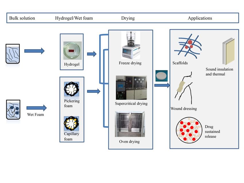
Materials 2020, 13, 5568                                                                             2 of 21

which hinders the diffusion of gas in bubbles and slows down the coarsening of bubbles [11]. MFC is
a mixture of cellulose with different morphology and size, which is mainly obtained from plant
fiber by mechanical treatment. It is a basic fibril bundle composed of less-ordered regions. Its main
component is NFC (within 100 nm in diameter), and there are also fiber fragments and microfilaments
with diameters ranging from several hundred nanometers to several microns. Due to the thixotropic
viscosity characteristic of NFC, it will produce “gelation” reaching a certain concentration to increase
the viscosity of the system and slow down the “Ostwald ripening” of foam.
       Maintaining the network structure of foam or minimizing its degree of damage is a common
problem in the process of preparing light and strong solid porous materials. According to a large
number of literature reports, there are two main ways to solve this problem, one is to increase the
stability of wet foam, and the other is to obtain solid foam with 3D network structure by optimizing the
drying process. The former is the premise of the latter. For wet foam, to enhance the stability of foam
is to establish Pickering foam and capillary foam by adding surfactants, polymers or nanoparticles to
bulk solution. Drying methods are mainly divided into freeze drying [12], supercritical drying [13]
and oven drying [7,8,10]. Freeze drying is most commonly used, but because of its complex operation
and high cost, it is not suitable for large-scale production. At present, it remains in the laboratory
stage. Supercritical drying is not widely used because of its complex operation and high requirements
on equipment. Compared with the former two methods, the natural air drying or oven drying,
the operation is simple, and it is easy to realize industrial production, but the pore size will be larger,
and the network structure of foam will be easily damaged due to the existence of gas–liquid interface
pressure during drying. At present, cellulose-based foam is still staying in the laboratory, and has not
yet achieved industrial production. Compared with EVA (ethylene vinyl acetate) and EPS (expanded
polystyrene) foam boards which already exist and are widely used in the market at present, the porous
foam materials made of cellulose are biodegradable, non-toxic and harmless, and environmentally
friendly. Different preparation methods of cellulose-based porous foams with different properties have
been widely reported in the literature up to now, and the potential applications in various fields have
been expounded. For example, it can be used as a cushion for portable devices due to its light weight,
firmness and porosity. At the same time, it can also be applied to biomedical applications such as
wound dressing [14], tissue scaffolds [15–19] and drug release [20–24], as shown in Figure 1. In addition,
the foam porous structure can be used for liquid absorption [25–27] such as sewage treatment and
water–oil separation [28–31]. Some porous materials also have low thermal conductivity, which can be
used as thermal insulation materials [2,9,32–36]. Also, foam can be used as sound insulation [37,38]
and materials to make wall sandwich panels. However, at present, cellulose-based foam materials are
still in the research stage and have not been put into industrial production.
       Figure 2 summarizes the published quantity of cellulose foam materials in the past 10 years, and the
data are provided by the Science Direct database. It can be seen that more and more attention has
been paid to cellulose-based porous materials, and there is a great space for development. The foam
forming is a novel technique for producing bulk materials with low density and high porosity. It is
a comprehensive, well-structured approach. As regards the other review articles already published
on this topic, this paper describes two stabilization mechanisms of MFC/NFC stabilized wet foam:
Pickering foam and capillary foam, in which MFC and NFC play the role of stabilizing particles, At the
same time, we introduce the main mechanisms of both, the recent research progress and potential
application prospects of cellulose porous foams in recent years are reviewed, and the main problems and
solutions for the preparation of cellulose porous foams are also summarized. In particular, we describe
two stable systems for wet foam: Pickering foam and capillary foam., so as to provide a reference for
future research.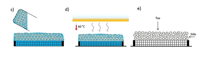
Materials 2020, 13, x FOR PEER REVIEW                                                                  3 of 23
Materials 2020, 13, x FOR PEER REVIEW                                                                                         3 of 23
Materials 2020, 13, 5568                                                                                                       3 of 21

                       Figure 1. The stability approach and main application of cellulose-based porous materials.

           Figure 1. The stability approach and main application of cellulose-based porous materials.

          Figure 1. The stability approach and main application of cellulose-based porous materials.

     Figure 2. The annual amount of scientific publications obtained through Science Direct with the subject
     of “cellulose foam; cellulose aerogel”.

2. Preparation of Porous Foam Materials

2.1. Process from Suspension to Solid Foam
     The preparation process from suspension to solid foam is generally divided into five steps (as shown
in Figure 3). The first step is the preparation of fiber suspensions. Cervin et al. [7] used modified NFC
as a stable particle, and in order to increase the adsorption of fibers at the interface, octylamine was
added to the suspension, and the wet foams were formed by high-speed stirring, then the foams were
placed on the pre-soaked porous ceramic sheets, and finally dried in an oven to obtain the solid foams.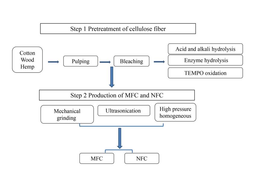
obtain the solid foams.
Materials 2020, 13, 5568 4 of 21
Figure 3. Schematic illustration of the process of the nanofibrillated cellulose (NFC)-stabilized solid
foams: (a) NFC suspension with a content of 1 wt%, (b) dry porous ceramic frit, (c) wet foam on
top of ceramic frit, (d) oven drying at 60 ◦ C, (e) solid foam after drying. (Adapted from Cervin and
Figure 3. Schematic
Johansson illustrationfrom
[28] with permission of the process
Acs of the Interfaces).
Appl Mater nanofibrillated cellulose (NFC)-stabilized solid
foams: (a) NFC suspension with a content of 1 wt%, (b) dry porous ceramic frit, (c) wet foam on top
2.2. Preparation
of ceramic of Nanofibrillated
frit, Cellulose
(d) oven drying (NFC)
at 60 °C, (e)and Microfibrillated
solid Cellulose
foam after drying. (MFC)from Cervin and
(Adapted
Johansson
Over [28] with
the years, permission
cellulose from Acs
has been Appl Mater
involved Interfaces).
in a wide range of fields, especially NFC and MFC,
which have the characteristics of ultra-light, high porosity and high strength, and have been used in
2.2. Preparation
composite of Nanofibrillated
materials Cellulose
in the past [39]. (NFC)
In recent and with
years, Microfibrillated
the shortageCellulose (MFC) resources and the
of petroleum
improvement
Over theofyears,
people’s awareness
cellulose of environmental
has been involved in a protection,
wide rangecellulose-based foam NFC
of fields, especially materials have
and MFC,
become potential
which have materials to replace
the characteristics plastic foam
of ultra-light, highboards
porosityin the
andmarket. Cellulose
high strength, is abundant
and have beeninusedalgae,
in
invertebrates and some bacteria [40], and also exists in the primary wall in
composite materials in the past [39]. In recent years, with the shortage of petroleum resources andthe cell walls of plants
such as hemp, wheat
the improvement straw, rice
of people’s straw and
awareness bagasse. Moreover,
of environmental the cell
protection, walls of plants
cellulose-based alsomaterials
foam contain
lignin, hemicellulose
have become potentialandmaterials
other accompanying materials,
to replace plastic foamwhich
boardswrap cellulose.
in the market. When extracting
Cellulose NFC
is abundant
and
in algae, invertebrates and some bacteria [40], and also exists in the primary wall in the cell walls is
MFC, it is necessary to remove these associated substances to expose cellulose, so pretreatment of
usually added.
plants such as NFC
hemp, and MFCstraw,
wheat have high
rice aspect ratiobagasse.
straw and and excellent mechanical
Moreover, the cellproperties
walls of which
plants can
also
be degraded
contain and hemicellulose
lignin, regenerated [39]. andIt is filamentous
other in morphology,
accompanying but which
materials, in practical
wrapapplication,
cellulose. it is a
When
network structure formed by winding, interweaving or connecting nanometer
extracting NFC and MFC, it is necessary to remove these associated substances to expose cellulose, or micron filaments.
When dispersed inispolar
so pretreatment usuallyliquids, it can
added. NFCexpand into ahave
and MFC smooth gelaspect
high with thixotropic viscosity mechanical
ratio and excellent properties
in the suspension. It is a stable gel that can be used for storage or to
properties which can be degraded and regenerated [39]. It is filamentous in morphology,withstand freeze-thaw cycles.
but in
Thereapplication,
practical are many preparation methods
it is a network for NFCformed
structure and MFC. Figure 4 shows
by winding, the stepsor
interweaving of connecting
extracting
MFC and NFC from natural plants. The preparation methods of both are similar, and the main
difference is related to the size of the extracted cellulose nanofibers. The diameter of MFC is generally
in the micron level, and the length is mainly distributed in the micron or even mm, while the relative
diameter of NFC is mainly distributed in the nanometer level, and the length distribution mainly
depends on the subsequent craft. NFC usually adopts high-pressure homogenization, which usually
requires high-pressure homogenization to make its particle size distribution small and uniform,
while mechanical grinding is the most common and easy to extract MFC. Their preparation methods
can be roughly divided into chemical methods, biological methods and mechanical methods. In the
actual extraction process, pretreatment methods [41,42] (acid, alkali, enzyme and oxidation, etc.)
are combined with the above three methods to improve the ratio of length to diameter and the yield of
fibers, and at the same time reduce the energy consumption of the whole process. Table 1 compares
MFC and NFC made by different raw materials and methods.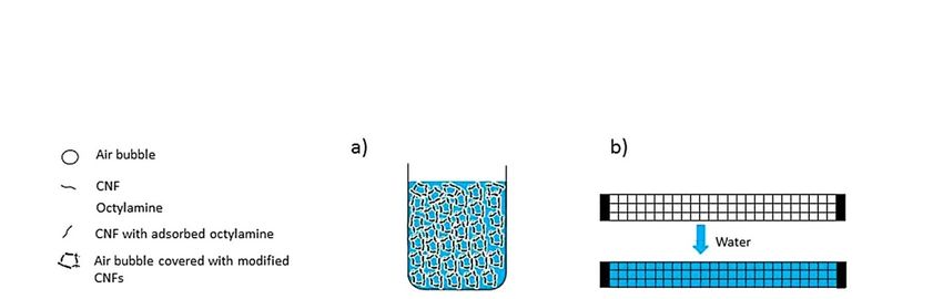
can be roughly divided into chemical methods, biological methods and mechanical methods. In the
             actual extraction process, pretreatment methods [41,42] (acid, alkali, enzyme and oxidation, etc.) are
             combined with the above three methods to improve the ratio of length to diameter and the yield of
             fibers, and at the same time reduce the energy consumption of the whole process. Table 1 compares
             MFC and NFC made by different raw materials and methods.
Materials 2020, 13, 5568                                                                                                          5 of 21

         Figure 4. The steps of extracting microfibrillated cellulose (MFC) and NFC from natural plants.

                Table 1. Comparison of different preparation methods with different raw materials.
                     Figure 4. The steps of extracting microfibrillated cellulose (MFC) and NFC from natural plants.
  Materials                                           Name          Method               Particle                        Reference
  Kraft pulp bleached from
                       Tableconiferous wood
                             1. Comparison        NFCpreparation
                                           of different     TEMPO                       ± 0.3
                                                                                 D: 3.0raw
                                                                 methods with different       nm
                                                                                           materials.                       [43]
                                                            Mechanical           L: 1.2 ± 0.4 nm
           Materials
  Bleached Kraft pulp                               Name
                                                      NFC Method
                                                              —                     Particle
                                                                                         D: 35–40 nm            Reference   [44]
              Kraft pulp bleached from              NFC   TEMPO                     D: 3.0L:± 2.3 mm
                                                                                              0.3 nm
                                                                                                                  [43]
  —           coniferous wood                         NFC Mechanical
                                                              TEMPO                 L: 1.2D:
                                                                                           ± 0.4
                                                                                              4 ±nm1.4 nm                   [45]
              Bleached Kraft pulp                   NFC     —                       D: 35–40   nm ± 104 nm
                                                                                          L: 255                  [44]
                                                                                    L: 2.3 mm
  Kraft pulp bleached
                   — from coniferous wood NFC
                                            MFC TEMPO
                                                    Mechanical                      D: 4 ±D:
                                                                                           1.430nmum              [45]      [37]
                                                                                         L: 2.3 mm
  Bleached sulfite pulp from spruce                   NFC           Mechanical           D: 30 um                           [46]
                                                                                         L: 2–3 mm
  Commercial eucalyptus bleach pulp                   NFC           TEMPO                D: 20–50 nm                        [3]
                                                                    Homogeneous
  Birch bleached Kraft pulp                           NFC           Enzyme               D: 20 um                           [3]
                                                                    Homogeneous          L: 150–300 um
  Bleached sulfite softwood cellulose                 NFC           Enzyme               D: 5–10 nm, 100–500 nm             [5]
                                                                    Homogeneous
  Bleached wood pulp                                  NFC           Acid                 D: 16 ± 4 nm, 21 ± 7 nm            [47]
                                                                    Homogeneous          L: 616 ± 200, 732 ± 208 nm
  Bleached Kraft pulp                                 MFC           Fenton               D: 10–100 um                       [48]
                                                                    Mechanical           L: 0.2–7.5 mm
  Bleached hardwood Kraft pulp and soft               MFC           Enzyme               D: 60 um                           [49]
  acid bagasse sulfite pulp                                         Mechanical
                                          D: diameter of cellulose; L: length of cellulose.

     It can be seen from Table 1 that enzyme treatment and TEMPO-mediated oxidation (2,2,6,6-
Tetramethylpiperidinooxy) are the most commonly used pretreatment methods in practical application.
Martoïa et al. [3] used birch bleached kraft pulp as raw material to obtain fibers with different size
distributions through enzyme treatment and high-pressure homogenization, in which the smallest
nanofiber diameter was 20–50 nm, while the larger microfiber diameter reached 100–500 nm. Yang et al. [43]
obtained nanofibers with a diameter of 3 nm and a length of 1.2 um through TEMPO oxidation combined
with mechanical treatment, with an aspect ratio of 400. Compared with enzyme treatment, the size
distribution of cellulose obtained by TEMPO oxidation is more uniform, and the diameter is basically
controlled within 100 nm, while the size distribution of fiber obtained by enzyme treatment is wider,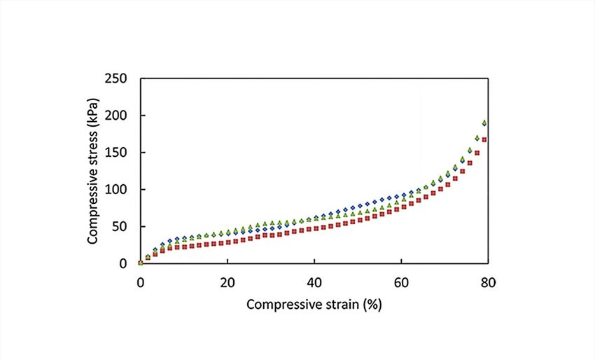
Materials 2020, 13, 5568                                                                            6 of 21

and both nanofibers and microfibers exist. In addition, some people put forward a new pretreatment
method. In 2014, it was proposed that catalyst pre-loaded Fenton oxidation method combined with
high pressure homogenization method was used to prepare MFC from hardwood dissolving pulp [48].
The concept of “micro-reactor” was put forward, which made up for the shortcoming that H2 O2 in
a traditional Fenton oxidation system had invalid decomposition before effectively oxidizing fibers,
and improved the production efficiency. The yield was also high, and the size distribution of the
prepared MFC was relatively uniform, with a diameter of about 200 nm and a length of tens or even
hundreds. In addition, some people added chemical reagents to optimize the whole extraction process
based on the above methods. In 2015, Yue et al. [50] used bleached coniferous wood chemical pulp as
raw material to prepare NFC by synchronous method. This method used ZnCl2 with swelling effect as
pretreatment agent, and realized swelling and mechanical dissociation simultaneously when swelling
was combined with moderate mechanical pulping treatment.
     Among many treatment methods, the mechanical method (ultrasonic crushing, high-pressure
homogenization and grinding method) is the most commonly used, which does not need to use
chemical reagents and is widely used for environmental protection. However, due to its high energy
consumption, cellulose is usually pretreated (enzyme pretreatment, TEMPO oxidation) before this to
degrade it partially, so as to reduce energy consumption. The chemical method uses acid or alkali
to decompose cellulose into nanoscale or micron cellulose, which occurs in the amorphous region of
cellulose, because the structure of this area is loose and easy to degrade. However, this method is not
widely used because of the large amount of waste liquid, low yield and high cost. Biological methods
are mainly enzyme treatment methods, which hydrolyze cellulose under mild conditions for a long
time. In fact, this method is usually combined with other methods to improve production efficiency.
In addition, biological methods include microbial synthesis of bacterial cellulose (BC), which has the
advantages of excellent three-dimensional network structure and high hydrophobicity, and also has
unique physical and mechanical properties [51].

2.3. Preparation of Wet-Foam

2.3.1. The Processing from MFC/NFC Dispersions to Wet Foam
      Mechanical stirring (the so called Bartsch method) [8] is the most commonly used method to introduce
bubbles into solutions (surfactants are usually added). Meanwhile, in the Bikerman method [11,52]
gas (such as nitrogen, Carbon dioxide) can be introduced to foam by a pressure device. In addition,
foam can be generated by adding chemical reagents (such as 4-methylbenzenesulfonhydrazide and
Diethyl azodicarboxylate) [53,54], which are decomposed after heating. However, this method may
cause environmental pollution. Among the above three methods, mechanical stirring is widely
used because of its simple operation and no pollution in the environment. For mechanical foaming,
the choice of foaming agents, stirring rate and foaming agent content (surfactant concentration slightly
higher than the critical micelle concentration) are very important. Foaming agents are roughly divided
into two types. One is surfactants (the structure of different surfactants and their respective surface
tensions give them different foaming properties). Surfactants, because of their strong foaming ability,
are most widely used, while proteins are only mainly used in food [55]. Although its foaming ability
is mediocre, its stability is better than that of the surfactants. Secondly, during the foaming process,
the stirring rate is also very important, the faster the rotating speed, the shorter the foam time to
reach the maximum volume. When the rotation speed is low, the air is entrained into the suspension.
Large bubbles will form, are gradually sheared and decomposed into smaller bubbles, finally shear
thinning occurs. If a pressure device is used to force a gas into a liquid to produce a bubble, the most
important of which is the selection of the gas. During the formation of the bubbles, the foaming agent
molecules are closely aligned at the gas-liquid interface and envelop the gas. The decay of the bubbles
is largely due to the coalescence and coarsening of the bubbles (more detail is described below), both of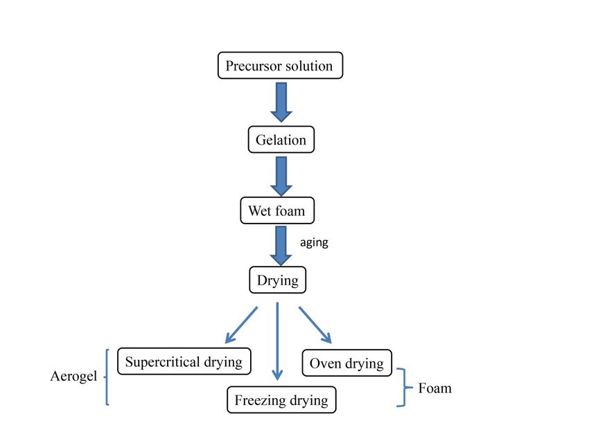
Materials 2020, 13, 5568                                                                                 7 of 21

which are derived from the diffusion and escape of the gases in the bubbles. Therefore, the use of less
water-soluble gases gives better stability, and bubbles can remain spherical for longer periods of time.

2.3.2. Wet Foam Stabilization Mechanism
      Foam is a metastable system, which is prone to decay under certain conditions, that is, foam instability.
There are three causes of foam instability, among which liquid drainage mainly occurs in Plateau
channel, under the action of gravity and surface tension, the liquid in bubbles will tend to be discharged
to the outside world; Bubble coalescence is mainly due to the weakening of the liquid film due to
the drainage intensity, the bubble becomes unstable and finally coalesces; According to the Laplace
equation, bubble coarsening is because the gas pressure in small bubbles is greater than that in large
bubbles, and there is a pressure difference between them. Gas diffusion occurs in small bubbles and
enters large bubbles. Eventually, small bubbles get smaller and disappear, and large bubbles get bigger
and eventually rupture. The basis of evaluating foam stability mainly includes liquid film thickness,
bubble size, and foam drainage rate [11,56]. With the extension of time, bubble volume will gradually
increase, drainage will be accelerated, liquid film will become thinner and thinner, bubble coalescence
will occur, and finally bubbles will rupture. The structure of foam is complex, and there are many
influencing factors, such as the viscosity of the solution, viscoelasticity of the gas–liquid interface,
and selection of the stabilizer.
      Based on the instability mechanism mentioned above, there have been a large number of reports
on how to improve foam stability. The main methods can be summarized into three types: one is to
stabilize by surfactants [8,11,57], the other is to stabilize by polymers [58,59], and the other is to stabilize
by hydrophobic or hydrophilic nanoparticles [60,61]. Surfactants are mainly due to having bipolar
groups (hydrophilic group and hydrophobic group). In the foam forming process, surfactants will be
arranged in an orderly way on the surface of liquid film wrapping gas, in which hydrophilic group
points to water and hydrophobic group points to air [62]. When the concentration is low, it mainly
exists in the form of molecules at the interface. When the critical micelle concentration is reached,
the interface adsorption reaches saturation and micelles are formed. Its stability mechanism is mainly
through electrostatic repulsion, which is characterized by strong foaming ability, but bubbles are less
stable and prone to collapse. When polymers are added as stabilizers, some polymers will interact with
surfactants [57,63]. When the concentration of polymers in surfactants reaches the critical aggregation
concentration (CAC), aggregates will be generated and stay at the channels and nodes, which slows
down the drainage of bubbles and the growth of bubbles. At the same time, due to the viscosity of
polymers, “particle bridging” will occur, which will wrap hydrophilic or hydrophobic nanoparticles
on the surface of liquid membrane and connect with each other, thus promoting the formation of
networks and increasing the viscosity of the gas–liquid interface.
      The Figure 5 shows the stabilization mechanisms of wet foam at present, which are mainly divided
into two types: one is the Pickering foam system (Figure 5a), and the other is the Capillary foam system
(Figure 5b). In these two systems, anionic surfactant is used as foaming agent (usually, the number of
carbon atoms is 12 or 14. When the carbon chain is short, the formed surface film has low strength,
and when the carbon chain is long, it will be difficult to dissolve, and the formed surface film is too
rigid to maintain stability), among which sodium dodecyl sulfate (SDS) is the most common one,
while NFC or MFC are used as stable particles.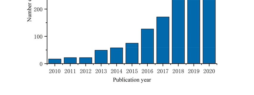
Materials 2020, 13, x FOR PEER REVIEW 10 of 23
Materials 2020, 13, 5568 . 8 of 21
Figure 5. The stabilization mechanism of wet foam: (a) the structure of Pickering foam; (b) the structure
of capillary foam.
Figure 5. The stabilization mechanism of wet foam: (a) the structure of Pickering foam; (b) the
2.3.3. Pickering
structure ofFoam of MFC
capillary foam.and NFC
In recent years, with the development of nanotechnology, the use of nanoparticles to stabilize
2.4. Preparation of MFC-/NFC-based Porous Solid Foam
foam has become the mainstream. Compared with the porous materials made by ionic liquid and
chemical Thecrosslinking,
preparation the foam made
of porous solid by Pickering
materials foamincludes
mainly has higher threefoaming rate and
steps (Figure 6):isthe
more
firststable
step is
because
sol-gel of the stabilization
transformation of particles.
(gelation), Pickering
the second step isfoam is a kind
network of wet(aging),
perfection foam stabilized
and the third by small
step is
solid particles, which
gel transformation are adsorbed
(drying on thethe
stage). Firstly, interface
precursor between
materialtwo is immiscible
dispersed inphases (water/oil
appropriate liquid orto
air/water) [64], Gonzenbach
form colloids, and then bubbles et al. [65]
areused this method
introduced to make to prepare
wet foam. super-stable
During the foam, while
drying cellulose
process, the
based
foamPickering
begins to agefoam anduses
theNFC
foamand MFCstructure
network as solid particles
is gradually to be adsorbed
shaped. on the interface
Cellulose-based porousof two
foam
phases
materialto achieve stability.
is obtained Figure 5a shows
by removing solventPickering
from wet foam withand
foam, MFC itsand NFC process
drying as stabilizing particles,
determines the
which are enriched
porosity, density and in the outer
other side of bubbleofliquid
characteristics filmsolid
the final and plateau
foam. Itchannel, and wrapped
is a big problem around
to ensure that
the
thebubble
foam to canform a protective
maintain granular
its original layer
porous [66], which
network reduces
structure thedrying,
after interference
withoutof external
deformation fluid and
to
the inner environment of bubble. The stability mechanism of the system mainly
collapse. When moisture evaporates, it will produce stress caused by capillary force, which will cause comes from changing
the
therheology
deformation of bulk solution
of voids andfoam
to cause gas-liquid
rupture, interface.
warping MFC and NFC
and collapse haveInthixotropic
[72,73]. view of thisviscosity
problem,
characteristics,
many scholarswhich have will form stable
developed somegel after absorbing
drying technologies waterto and swelling,
minimize the which
damage makes
degree theof fibers
foam
more
poroustightly adsorbed
network and entangled
structure, but eachon the surface
method has itsofownthe liquid membrane
advantages to form a stable
and limitations. network
It can be seen
structure,
from Table enhances the interfacial
2 for details. At present,viscoelasticity, prevents the
the most commonly useddeformation
methods are (thinning)
naturaland dryingrupture of
or oven
the liquid freeze-drying
drying, membrane, andand slows down the drainage
supercritical of the foam.
drying, among which Secondly, due to the
freeze-drying increase
is the mostofrapidly
fluid
volume
developed,and thebutincrease of viscosity
freeze-drying is notofsuitable
the bulk forsolution,
large-scalethe free movement
production of active
because of itsmolecules
high energy is
reduced,
consumptionresulting
andinhighthe decrease of desorption
cost. Supercritical dryingratehas
of high
surfactant at the interface,
requirements in termsand the bubble is
of equipment andin a
a complex
relativelyoperation,
stable statewhich
withinisa notcertain period
suitable forofindustrial
time. Xiang et al. obtained
production. the corresponding
Natural drying or oven storage
drying
modulus
has simple (G’), dissipation
operation andmodulus (G”) and
low equipment complex viscosity
requirements, but the(η*)porebysize
comparing the viscoelasticity
distribution of the obtained
offoam
gas-liquid
is notinterface
uniformunder enough.the oscillation
Therefore,ofthe onlydrying
SDS and the coexistence
method is one ofofthe SDSbottlenecks
and NFC [11,57]. in the
The results show
development of that
solidNFCporousdoesmaterials
play a thickening
at present.roleMany andpeople
endows thedifferent
take gas-liquid interface and
optimization bulk
methods
solution
to solve with
thecertain viscoelasticity,
disadvantages of theconfirmed the above statement.
above processes in order toInobtain2013, Cervin et al. [7] developed
high-porosity solid foam
Pickering
materialsfoam withusing
goodNFC as a stabilizer
properties (Table 3) toby
produce
a simple cellulose foams with
and low-energy good mechanical
drying method. properties,
and proposed that the presence of particles resists the shrinkage and growth of the bubble volume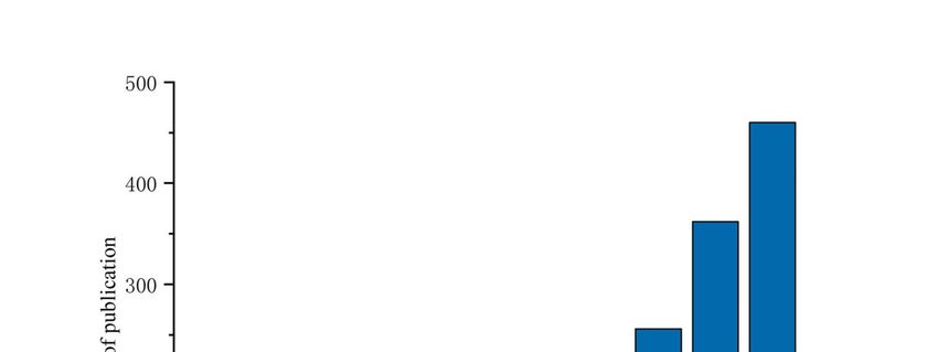
Materials 2020, 13, 5568                                                                           9 of 21

compared to a surfactant-based system, Pickering foam greatly increases the foam life cycle and exhibits
excellent stability. The final foam density is 0.03 g cm−3 , the porosity is up to 98%, and the pore size
is about 500 um. At the same time, the mechanical properties of the foam were greatly enhanced,
and its compressive strength was as high as 437 ± 63 kPa. Using MFC/NFC as the particle stabilizer,
Liu et al. [67] prepared a three-dimensional ultra-lightweight foam with a density of 0.1 kg cm−3
and a porosity of 90%. It is found that Pickering foam can greatly increase the lifetime of foam [66],
which is beneficial to the application of foam-cleaning products. However, it is far from enough for the
preparation of porous solid foam with high porosity and cross-linked network structure to maintain
its existing network structure when dried. Therefore, on this basis, Koos put forward the concept of
capillary foam in 2014, and found that the addition of secondary liquid can significantly improve the
stability of foam and reduce the collapse of structures [68].

2.3.4. Capillary Foam
     Capillary foam is produced on the basis of Pickering foam, and the latter can be regarded as
the precursor of the former. The color wet foam and dry foam which are difficult to be prepared
by traditional methods can be made, which greatly reduces the difficulty of product processing [66].
By adding the immiscible second liquid into Pickering foam, the bulk solution will be converted from
viscous fluid to elastic gel to form capillary foam (as shown in Figure 5b). Capillary foam is a new
type of foam material, which uses the synergistic effect of particles and a small amount of immiscible
secondary liquid to achieve stability [68–70]. The second liquid is usually a polymer with high viscosity
coefficient, such as gelatin, agar, xanthan gum, etc., but it is wrong to simply think it Pickering foam
with polymer added, because the addition of the second liquid will spread at the gas–liquid interface,
playing the role of bridging particles and promoting the formation of a network. At the same time,
the addition of the second liquid can also play an auxiliary wetting role, which makes the fibers
more easily absorbed on the gas–liquid interface, maintain stability and increase the viscosity of the
system. After the foam is dried, the fibers serve as the main skeleton of the foam, which mainly plays
a supporting role. After the capillary foam added with the second liquid is dried, the fibers pile up
more compactly, and the overall mechanical properties are improved, so that the foam can maintain its
original network structure after drying. In 2014, Ahsan et al. [71] used microcrystalline cellulose as
stable particles and added polymer chitosan, and found that the composite dispersion appeared gelation
behavior at pH = 7. The synergistic effect of chitosan and MCC (Microcrystalline cellulose) enhanced
molecular entanglement and produced synergistic network structure. As a result, foam with porous
structure was prepared under this condition, and its energy absorption was as high as 32.86 kJ/m3 .

2.4. Preparation of MFC-/NFC-Based Porous Solid Foam
     The preparation of porous solid materials mainly includes three steps (Figure 6): the first step is
sol-gel transformation (gelation), the second step is network perfection (aging), and the third step is
gel transformation (drying stage). Firstly, the precursor material is dispersed in appropriate liquid
to form colloids, and then bubbles are introduced to make wet foam. During the drying process,
the foam begins to age and the foam network structure is gradually shaped. Cellulose-based porous
foam material is obtained by removing solvent from wet foam, and its drying process determines the
porosity, density and other characteristics of the final solid foam. It is a big problem to ensure that
the foam can maintain its original porous network structure after drying, without deformation and
collapse. When moisture evaporates, it will produce stress caused by capillary force, which will cause
the deformation of voids to cause foam rupture, warping and collapse [72,73]. In view of this problem,
many scholars have developed some drying technologies to minimize the damage degree of foam
porous network structure, but each method has its own advantages and limitations. It can be seen from
Table 2 for details. At present, the most commonly used methods are natural drying or oven drying,
freeze-drying and supercritical drying, among which freeze-drying is the most rapidly developed,
but freeze-drying is not suitable for large-scale production because of its high energy consumption and
Materials 2020, 13, 5568 10 of 21
high cost. Supercritical drying has high requirements in terms of equipment and a complex operation,
which is not suitable for industrial production. Natural drying or oven drying has simple operation
and low equipment requirements, but the pore size distribution of the obtained foam is not uniform
enough. Therefore, the drying method is one of the bottlenecks in the development of solid porous
Materials 2020, 13, x FOR PEER REVIEW 11 of 23
materials at present. Many people take different optimization methods to solve the disadvantages
of the above processes in order to obtain high-porosity solid foam materials with good properties
(Table 3) by a simple and low-energy drying method.
Figure 6. A flow chart on preparation of porous solid materials.
Table 2. AFigure 6. A flow
comparison chart on
of drying preparation
approaches forof poroussolid
various solidfoam.
materials.
Name Method Particle
Table 2. A comparison of drying approaches Advantages
for Disadvantages
various solid foam.
Supercritical drying Replacing the solvent with supercritical fluid Nanosize Dimensions stay in Expensive and
Name Method
(methanol, ethanol and CO2 ) Particle Advantages
nanosize Disadvantages
complicated method
Freezing drying Precooling at −4 ◦ C and freezing in liquid nitrogen nm to um Establish a good Expensive
Supercritical Replacing the solvent with Nanosize Dimensions stay Expensive and
then freezing overnight in a frozen drying oven network structure
drying supercritical fluid (methanol, in nanosize complicated
Oven drying Drying in the oven at 105 ◦ C for 24 h um to mm Well established for Severe structural
ethanol and CO2) the industry method
collapse
Freezing Precooling at −4 °C and nm to Establish a good Expensive
dryingDrying freezing in liquid nitrogen
2.4.1. Freezing um network
then freezing overnight in a structure
Freeze-drying mainly uses the principle of sublimation to freeze wet foam at low temperature,
frozen drying oven
and then sublimes it under vacuum. After sublimation of ice crystals, holes will be left, and porous
Oven Drying in the oven at 105 °C um to Well established Severe structural
solid foam materials can be prepared. The freezing speed plays an important role in the microstructure
drying for 24h mm for the industry collapse
and compressibility of solid foam [4]. In 2017, Gupta et al. [74] focused on the use of ice-templates
(after freezing of suspensions and sublimation of the formed ice crystals) to produce porous cellulose
2.4.1. Freezing Drying
based materials, and discussed the influence of processing conditions such as temperature gradient and
freezing rateFreeze-drying
on foam morphologymainly during
uses the theprinciple
freezingof sublimation
process In 2008,toPääkkö
freeze etwetal. foam at low for
[5] reported temperature,
the
and
first time then
that sublimes
aerogels withitgood
underelectrical
vacuum.conductivity
After sublimation of ice crystals,
were prepared by two holes willfreeze-drying
different be left, and porous
methods: solid
low foam materials
temperature can be In
and vacuum. prepared. The freezing
low temperature speed the
freeze-drying, plays
moldan important
containing role in the
hydrogel
microstructure
was quickly immersed in and compressibility
liquid propane at −180 ◦ C, and
of solid foam [4].
then theInfrozen
2017,samples
Gupta et al. [74]
were placedfocused on the use of
in a vacuum
ice-templates(after
oven until the pressure was freezing
kept at 1 × −2 mbar. In vacuum
of10suspensions and sublimation of the
freeze-drying, theformed ice with
mold filled crystals) to produce
hydrogel
was putporous celluloseoven,
into a vacuum based thematerials,
gel was frozenand quickly,
discussed andthetheinfluence
ice crystalsofwere
processing
sublimatedconditions
until thesuch as
temperature gradient and freezing rate on foam morphology during the freezing process In 2008,
Pääkkö et al. [5] reported for the first time that aerogels with good electrical conductivity were
prepared by two different freeze-drying methods: low temperature and vacuum. In low temperature
freeze-drying, the mold containing hydrogel was quickly immersed in liquid propane at −180 °C, and
then the frozen samples were placed in a vacuum oven until the pressure was kept at 1 × 10⁻² mbar.Materials 2020, 13, 5568 11 of 21
pressure was kept at 1 × 10⁻² mbar. The aerogel prepared by the above two methods has a porosity of
98% and a density of 0.02 g/cm3 , in which the specific surface area of low-temperature freeze-drying is
66 m2 /g and that of vacuum freeze-drying is 20 m2 /g. When the freezing speed is low, ice crystals will
nucleate and grow spontaneously, while when the freezing speed is high and the temperature is low,
the number of ice crystal nuclei is large, the volume of ice crystals is small, and the gaps formed are
smaller and uniform. When freezing at low temperature, water pushes MFC and NFC in the process of
forming ice crystals, and finally gathers between ice crystals. When ice crystals volatilize, dense porous
structures will be formed, and MFC and NFC act as skeletons in the whole structure, thus ensuring the
mechanical properties of solid foam. Subsequently, more and more people adopt similar methods to
prepare aerogels with various properties [2,75,76]. Han et al. [47] put the fast freeze-drying flask filled
with NFC and CNC (cellulose nanocrystals) suspensions with different concentrations in an ultra-low
temperature freezer at −75 ◦ C for two hours, and then transferred it to a freeze dryer for vacuum
freeze-drying at −88 ◦ C for three days, thus obtaining a layered foam structure with a pore size of 0.5–3 um.
Compared with CNC, the foam fracture surface made by CNF with larger size is not as smooth as the
former, and the cellulose concentration and fiber surface charge will affect the self-assembly behavior of
fibers. Korhonen et al. [77] dried the MFC hydrogel in vacuum, and coated its surface with hydrophobic
modification. Finally, the ultra-light selective oil absorption material with density of 20–30 mg/cm3 and
porosity >98% was obtained.
In order to further reduce the entwined degree of fiber during freeze-drying and increase the
specific surface area of the material, Sehaqui et al. [78] proposed to replace the traditional freeze-drying
with tertiary butyl alcohol. The results showed that the capillary action was lower in the presence of
tert-Butyl alcohol (TBA), and the surface area of aerogel obtained was as high as 332 m2 /g. In the prior
art, freeze-drying is a versatile method for preparing foam biomaterials with controllable structure,
and the properties of the materials can be easily adjusted by controlling their microstructure, so it is
widely used [3]. However, due to its high price, industrial production has not yet been realized. In order
to reduce the problem of high energy consumption of the freeze drying Josset et al. [53] proposed a
straightforward freeze—thawing—drying procedure; the method is based on urea is complementary
fertilizer increased the rate of ice nucleation, the MFC/urea suspension using ice template steps under
−45 ◦ C, and then thaw dehydration in the environment, and finally drying at 105 ◦ C. This method
solves the problem of the high cost of freeze-drying, and urea will be dissolved in water during
dehydration, which has the potential for reagents recovery and utilization. Foams and aerogels
prepared by freeze-drying have nanometer and micron pore sizes and good porosity, which can be
used in the fields of drug slow release, functional wall plywood, water-oil separation and so on.
2.4.2. Supercritical Drying
In addition to freeze drying, supercritical drying is also a common method to realize high specific
areas. It adopts a dry medium to replace the original solvent into supercritical fluid under critical
temperature and pressure conditions, and then releases the fluid slowly under reduced pressure.
Because supercritical fluid is a fluid between gas and liquid, the original gas/liquid interface no longer
exists, and there is no pressure attached to capillary force, thus avoiding the deformation and collapse
of foam structure caused by capillary force [79]. Commonly used drying media are methanol, ethanol
and carbon dioxide. Because methanol and ethanol are flammable and explosive, carbon dioxide is
widely used as drying media on a large scale. Compared with freeze-drying, the solid foam prepared
by supercritical drying avoids the problem of aggregation among freeze-drying fibers, and its density
is relatively low, the surface area is increased, and the pore size is mainly distributed in nanometer
level (Table 3). Compared with freeze-drying, supercritical drying is not so widely used. The specific
surface area value distribution range of the prepared porous materials is limited, mainly between
200–300 m2 /g, which is different from freeze-drying (specific surface area value difference is relatively
large). Deniz et al. [79] adopted a multi-stage solvent exchange process, in which ethanol is used
instead of water, and then ethanol is removed by supercritical CO2 to obtain aerogel with a density ofMaterials 2020, 13, 5568 12 of 21
0.009 g/cm3 . Freeze-dried aerogels (density: 0.023 g/cm3 ) were also prepared from the same materials.
It was found that light white spongy aerogels were obtained after removing water, and the structure did
not collapse obviously. The aerogels dried by SCCO2 (supercritical carbon dioxide) had lower density
and higher specific surface area. Wu et al. [6] used a supercritical drying method to dry cross-linked
foams and aerogels. The specific surface area was as high as 430 m2 /g, and the Young’s modulus
was as high as 711 kPa through physical and chemical cross-linking, which showed good mechanical
properties. At the same time, the layered double void structure of the material was obtained through
adsorption experiments on silver ions, which gave it considerable adsorption capacity and enabled it
to be applied in antibacterial fields. Aerogel prepared by supercritical drying can maintain a good
network structure because there is no gas-liquid interface in the drying process, and its pore size is
mostly nanoscale, but the requirements for equipment are relatively high. At the same time, toxic gases
may be produced during solvent replacement, therefore, it is necessary to control the speed of fluid
release during operation, and its development is limited due to high cost and complex operation.
Table 3. Comparing the properties of porous materials prepared by different drying methods.
Name Method Parameter Advantage Application Reference
Aerogel Freeze drying 514.15 m2 /g Good circulation stability High performance super [43]
2–10 nm capacitors
Foam Freeze drying 35.8 m2 /g Controllable structural Thermal insulation [9]
Aerogel Liquid nitrogen and 40.31 m2 /g Thermal resistance and high Personal protectable [80]
freeze drying 13.66 nm tenacity equipment
Foam Oven drying 300–500 µm Lightweight and strong _ [7]
98%
Aerogel Supercritical carbon 200 m2 /g _ Drug sustained release [81]
dioxide drying
Aerogel Supercritical drying 130–160 m2 /g Good hygroscopic wound dressing [44]
0.5 ± 0.2 µm property
Aerogel Freeze drying 20–30 m2 /g _ _ [44]
24.7 ± 10.4 µm
Aerogel Supercritical carbon 240–280 m2 /g Sound absorption Office ceiling [13]
dioxide drying 0.86–0.92 µm High intensity
91–96%
Foam Freeze drying 93–99.5% Porous and excellent New composite material [2]
mechanical properties for energy absorption
Aerogel Oven drying 70–120 m2 /g Excellent mechanical Green heat insulation [12]
properties building materials
water purification
material
Aerogel Freeze drying 70 m2 /g High strength and Functional conductive [5]
98% deformation material
Foam Oven drying 99.6% Water resistance and wet Water and oil separation [28]
elasticity
Aerogel Liquid nitrogen and 99.38–99.97% Controllable structural _ [48]
freeze drying
Aerogel Liquid nitrogen and 11–42 m2 /g Super hydrophobic Water and oil separation [29]
freeze drying 99.8–99.1%
2.4.3. Oven Drying
Compared with the above two methods, oven drying is the simplest and the cost is lower, which is
suitable for industrial production. However, the main problem at present is that the foam structure
collapses seriously during the drying process, and the optimization of drying process is not perfect
at present. Most of them are prepared by improving the stability of wet foam (such as Pickering
foam and capillary foam), and then combined with oven drying. The aperture is mostly micron-Materials 2020, 13, 5568 13 of 21
or even millimeter-scale, otherwise it is inhomogeneous and large cavities can easily appear in the
material. To solve this problem, Cervin et al. [28] used sulfite softwood dissolving pulp as raw material,
prepared NFC by TEMPO oxidation combined with high-pressure homogenization, and then added
octylamine to make NFC better adsorbed on the gas-liquid interface. After mechanical foaming,
the wet foam was placed in porous ceramic frit (soaked overnight, water filled the whole gap), and then
dried in an oven at 60 ◦ C. The density of the foam was 13 kg/m3 , and the porosity was as high as
99%. In the drying process, the ceramic plate is equivalent to a water reservoir, which can provide
liquid flow for the foam, avoid the intercommunication of liquid in the cavity and the rupture area,
and reduce the generation of independent air pockets, thereby improving the non-uniformity of the
pore diameter of the solid foam. In other literature by the author, it is shown that the addition of
octylamine makes the fiber more adsorbed on the gas-liquid interface, and there are more counter
ions around it, and the disjoining pressure between bubbles increases, which prevents bubbles from
coalescence and disproportionation [7]. Liu et al. [8] prepared MFC as stable particles from bagasse,
and formed capillary foam by adding secondary liquid (gelatin) into bulk solution, and dried it
in an oven (40 ◦ C–60 ◦ C) overnight, and finally prepared porous fiber foam with light weight and
high porosity.
3. Properties of Porous Foam Materials
3.1. Surface Area and Porosity
Porous foam materials can be used in drug carriers, adsorption and electrodes because of their
light weight, low density and high specific surface area [2]. In order to improve the high specific surface
area (SSA) of materials, it is very important for the specific surface area of porous materials that NFC is
well dispersed in solvent mixture. In order to prevent the fibers from gathering together to form larger
fiber bundles, which will lead to the increase of material density and decrease of SSA [82], the density
of materials can be reduced and the specific surface area can be increased by adding octylamine or
changing its concentration [28]. The most significant factors affecting the properties (density, specific
surface area and porosity, etc.) of porous materials are the initial fiber concentration and drying
process. Nissila et al. [83] confirmed that the initial concentration of NFC is directly proportional to the
density of aerogel and inversely proportional to porosity and specific surface area. Sehaqui et al. [78],
after mixing, centrifuging and removing supernatant before freeze-drying, firstly exchanged solvent
between water and ethanol, then exchanged solvent between ethanol and tert-Butyl alcohol (TBA),
and found that the specific surface area of aerogel finally made from fiber was 332 m2 /g. At the
same time, it has been suggested that supercritical CO2 drying will produce higher specific surface
area than freeze drying. Deniz et al. [79] adopted two methods to prepare aerogels at the same time,
and the results obtained confirmed this view. The specific surface area of supercritical CO2 drying was
115 m2 /g, and the porosity was as high as 99%, while that of freeze drying was 20 m2 /g, and the porosity
was 96%. The BET (Brunauer–Emmett–Teller) method and BJH (Barrett–Joyner–Halenda) method are
mainly used to calculate the specific surface area and pore size. In the freeze-drying process, due to the
shrinkage and collapse of small pores, the BJH method (pore size 1.7–300 nm, Heath and Thielemans,
2010) is more suitable [79].
3.2. Mechanical Properties
The mechanical properties of porous foam materials are mainly manifested in hardness, compressive
strength, etc. Secondly, in some application fields, the ability to resist deformation is also very important,
and the properties of materials often have a great relationship with the shape of materials. Some studies
have reported that there are three stages in the compression deformation of porous solids [2,38,72]:
(a) under yield stress, the elastic deformation of the material is linear, which is mainly caused by the
elastic deformation of cell wall bending and the compression of large pores; (b) the plateau area changes
from elastic deformation to plastic deformation. At this stage, with the increase of material deformation,Materials 2020, 13, 5568 14 of 21 the stress no longer changes, which means that the cell begins to collapse, and the structure suffers damage and no longer has resilience; (c) densification region, the cell walls are in contact with each other, and the porous structure is seriously collapsed. Based on this feature, Chen et al. [38] prepared an anisotropic whole biological CMC (carboxymethyl cellulose)/NFC aerogels by directional freeze-drying, which showed honeycomb structure. It was confirmed by compression and three-point bending tests that there were linear elastic regions with 30% elastic strain and 30–70% strain was plateau regions. Then came the densification region (70–90%), and the compression modulus in the vertical direction (8.7 MPa) was significantly higher than that in the horizontal direction (1.5 MPa). In addition, Kobayashi et al. [84] reported a new type of three-dimensional ordered NFC aerogel with a surface area of 500–600 m2 /g. The material showed a linear elastic region under 10% strain, and began to deform plastically after reaching the yield point. When the strain reached 60%, the densification region appeared and the skeleton became dense. Compared with ordinary aerogels, it had good optical properties and mechanical toughness, and its elastic modulus increased linearly with the increase of density, reaching a maximum of 1MPa. But most of the cellulose-based foams do not exhibit a compression behavior similar to that of the platform (as shown in Figure 7). This is related to the use of various processing routes. Cervin et al. [7] have created lightweight and strong NFC foam using Pickering foam processing route, they conducted compression experiments of NFC foam with a density of 0.05 g cm−3 and a porosity of 96.7%. Research has shown that that there was no platform area in this experiment. At 60% strain, the linear viscoelastic region appeared, and then followed densification region directly. The Young’s modulus is 437 ± 63 kPa according to the slope under low strain, and the compressive energy absorption is 48 ± 11 kJ m−3 at 80% strain. As a result, we can see that the mechanical properties of the solid foams produced by this process are comparable to other types of NFC foams, but the strength is lower than that of ordinary plastic foams, such as EPS (expanded polystyrene board) whose Young’s modulus is as high as 6000 kPa. The report also showed that the mechanical properties of the foam can be adjusted by changing the chemical composition and foaming composition of the NFC. A similar problem arose in Sehaqui’s [2] report, which found that the platform area where a typical elastoplastic polymer foam should be found did not appear in the report. In this paper, the porous MFC-based foams with high mechanical strength were prepared by freeze drying without solvent. Although the transition from linear stress-strain behavior to non-linear stress-strain behavior was gradual, it is clear that materials exhibit a collapse behavior that often results from the formation of plastic hinges due to plastic yielding of the cell wall materialization. At higher strains, the porous structure of the foam becomes densification, and the cell walls contact each other which result material to rigid. Wu et al. [6] have prepared the dual-porous NFC aerogels with good mechanical properties and high stability in water by physical/chemical cross-linking, the hydrophilicity and mechanical strength of aerogels can be precisely controlled, the most important of which is that the aerogels have dual-porosity. In comparison with other cellulose porous materials, the properties of macro-porosity and high strength of NFC foams are combined with the properties of Meso-porosity and high surface area of NFC aerogels. Both horizontally and vertically, the mechanical strength of the cross-linked materials is higher, and the mechanical strength of the cross-linked materials increases with the content of the NFC. Generally speaking, the mechanical strength of porous materials is inversely proportional to the network pore size, and the pore size mainly depends on MFC/NFC concentration and drying technology. It can be seen from Table 3 that compared with the other two drying methods, supercritical drying can form small and uniform pores. Lee et al. [85] prepared a unique and controllable microfiber porous foam by a unidirectional freezing method. When the microfiber concentration increased from 2% to 8%, the compressive stress was greatly increased (from 30.7 kPa to 366 kPa).It was found that the foam morphology changed with the increase of microfiber concentration. At low concentration, the foam showed a cross-linked network structure. With the increase of concentration, the cross-linked network gradually changed to a layered channel structure. When the concentration was 8%, the foam had formed a highly ordered channel structure parallel to the freezing direction, and the cell wall thickness increased.
You can also read