Nanofabricated DNA Curtains for High-throughput Single-Molecule Imaging of Protein-DNA Interactions
←
→
Page content transcription
If your browser does not render page correctly, please read the page content below
Microscopy: Science, Technology, Applications and Education
A. Méndez-Vilas and J. Díaz (Eds.)
______________________________________________

          Nanofabricated DNA Curtains for High-throughput Single-Molecule
          Imaging of Protein-DNA Interactions
          H. N. Wolcott1,3, B. Alcott1,3, L. Kaplan1 and E. C. Greene2
          1
            Department of Biochemistry and Molecular Biophysics, Columbia University, 650 West 168th Street, BB 536, New
             York, NY, USA
          2
            Howard Hughes Medical Institute
          3
            These authors contributed equally.

          Single-molecule imaging has emerged as a powerful new approach enabling biochemical reactions to be explored through
          real time visualization. However, these experiments remain technically demanding and by necessity are designed to look at
          individual reactions, which can make it challenging to collect statistically relevant data sets. To overcome this problem, we
          have developed a novel technology called “DNA curtains” that allows simultaneous visualization of hundreds of
          individual DNA molecules by total internal reflection fluorescence microscopy (TIRFM). The curtains are made by
          anchoring DNA to a fluid lipid bilayer, and then the individual DNA molecules are aligned along the leading edge of a
          barrier to lipid diffusion through the application of hydrodynamic force. Our current generation of devices use
          nanofabricated barriers made by either electron beam or nanoimprint lithography, and offer precise control over the
          geometry, dimensions, and configuration of the DNA curtains. These flexible new experimental platforms offer many
          advantages for real-time single-molecule fluorescence imaging of DNA molecules and protein-DNA interactions.

          Keywords single-molecule imaging; DNA curtain; nanofabrication; protien-DNA interactions

          1. Introduction
The interactions between proteins and nucleic acids are essential for many basic functions in living organisms. Cellular
processes such as DNA replication, repair and maintenance, RNA transcription, and protein synthesis are all dependent
upon the interactions between proteins and nucleic acids, and these interactions must be precisely regulated. Many
diseases, such as cancer, can be linked to molecular defects that adversely alter the functions or behaviors of specific
nucleic acid binding proteins.
    Protein-nucleic acid interactions are particularly amenable to single molecule techniques, which are capable of
revealing mechanistic details that would be impossible to discern using traditional ensemble experimental approaches,
and the field is profoundly impacting the way that biological macromolecules are being studied [1-6]. Single molecule
study is not, however, without its challenges. Experiments are technically demanding and setups are frequently suited
only for a narrow range of applications. Two problems in particular are the need for “biologically friendly” surfaces
compatible with the biological macromolecules, and the practical difficulties faced when trying to obtain statistically
relevant data sets. The need for biologically friendly surfaces arises from the fact that most single molecule approaches
are reliant upon the use of surface based detection strategies, and it is absolutely essential that the surfaces required for
these studies be completely passivated to minimize the possibility that proteins will become inactivated by attachment
to a surface support [7]. Obtaining statistically relevant data sets is problematic because the experiments are typically
designed to look at just one or a few reactions at a time.
   To address these issues, we have developed a technology called “DNA curtains” in which we utilize a combination
of lipid bilayers, physical barriers to lipid diffusion, and hydrodynamic flow to organize lipid-tethered DNA molecules
into defined patterns on the surface of a microfluidic sample chamber [8-11]. The lipid bilayer mimics naturally
occurring surfaces found in living cells and is biologically friendly, while the barriers are used to arrange thousands of
individual molecules that can be simultaneously visualized. This experimental setup allows for real-time data collection
and is flexible enough to be easily adapted to a number of biochemical problems.

          2. Total Internal Reflection Fluorescence Microscopy
Our DNA curtain technology relies upon the use of TIRFM to visualize fluorescently tagged protein and DNA
molecules [12]. For TIRFM, a laser beam is directed through a microscope slide and reflected off the interface between
the slide and an aqueous buffer to generate an evanescent wave at the slide surface (Fig. 1). The evanescent wave
penetrates only a few hundred nanometers into the sample and therefore yields a very small excitation volume, which
serves to minimize laser excitation of contaminants and molecules in bulk solution, thereby reducing the background
signal by several orders of magnitude relative to conventional wide-field illumination techniques [12].

722                                                           ©FORMATEX 2010
Microscopy: Science, Technology, Applications and Education
                                                                                                 A. Méndez-Vilas and J. Díaz (Eds.)
                                                                       ______________________________________________

The TIRFM systems in our laboratory employ a simple through-prism illumination configuration built around inverted
Nikon TE2000U microscopes [8-11]. The excitation source is provided by a diode-pumped solid-state laser, which is

                                                                                  Fig. 1 TIRF microscope. a) The system
                                                                                  is built around a Nikon TE2000U
                                                                                  microscope. A laser is focused through
                                                                                  a prism onto the sample chamber to
                                                                                  generate an evanescent wave. Images
                                                                                  are collected with an objective lens and
                                                                                  recorded by a back-illuminated
                                                                                  electron-multiplying CCD         camera
                                                                                  (EMCCD). An image-splitter is used to
                                                                                  separate different wavelengths. a) Side-
                                                                                  view of the microscope. The EMCCD
                                                                                  can be seen in the bottom left corner.
                                                                                  The image-splitter is in front of the
                                                                                  EMCCD. c) Side-view of laser
                                                                                  illuminated flowcell.

focused through the fused silica prism onto a microfluidic flowcell to generate the evanescent wave within the sample
chamber. Beam alignment is controlled by a remotely operated motorized mirror that guides the beam to the prism.
Images are collected with an objective lens, passed through a notch filter to reject scattered laser light, and are detected
using a back-illuminated electron-multiplying CCD camera. When used for multi-color operation, the images are passed
through an image-splitter containing a dichroic mirror that separates the optical paths. The microscope is mounted on an
optical table to minimize vibrations and facilitate mounting of optical components. TIRFM experiments require
microfluidic flowcells that are machined and assembled in house, as described [11, 13, 14].

         3. DNA Curtains as a Tool for Single-Molecule Imaging
The idea for DNA curtains came from the understanding that DNA molecules anchored to a fluid lipid bilayer would
move in the direction of an applied hydrodynamic force while remaining tethered to the bilayer. A physical barrier
oriented perpendicular to the flow would halt progression of the moving DNA causing the molecules to align along the
leading edges of the barriers. Organization of the DNA along the barrier would potentially make it possible to visualize
hundreds or even thousands of DNA molecules all within a single field of view.

         3.1   Technology overview
The general strategy for making the DNA curtains is outlined in Figure 2. First, a lipid bilayer is deposited onto the
surface of a microfluidic sample chamber. The bilayer passivates the fused silica surface by rendering it inert to most
biological macromolecules, and creates mobile anchor points for the DNA molecules limiting their motion to the 2D
plane of the surface. A subset of the lipids within the bilayer have biotinylated head groups which are used as
attachment points for DNA molecules that are coupled to them through a biotin-streptavidin linkage. When buffer is
passed through the sample chamber, the DNA molecules experience a hydrodynamic force. Since they are free to
diffuse in two dimensions, the application of flow force pushes the molecules through the chamber, with the tethered
DNA ends still attached to the bilayer. Micro- or nanofabricated barriers to lipid diffusion disrupt the continuity of the
bilayer at strategically selected positions, which in turn halts the movement of the DNA molecules (see below). The
resulting pattern of organized DNA molecules bears a physical resemblance to a curtain [8, 9, 11].

         3.2   Microfabricated barriers to lipid diffusion and assembly of DNA curtains
Our initial DNA curtains relied upon lipid diffusion barriers that were made by manually etching the surface of a fused
silica slide with a diamond-tipped scribe (Fig. 3A) [8, 15]. The bilayer uniformly coats the entire surface of the slide,
but it is physically disrupted at the manually etched barriers. This technique was based upon the findings of Boxer and
colleagues, who demonstrated that lipids were unable to traverse manually etched microscale barriers (i.e. scratches) on
a glass surface [16, 17]. Once etched, the slide is assembled into a flowcell and a lipid bilayer is deposited onto the
surface, as previously described [8, 11, 14].
    Manually etched barriers offer the simplest method for making DNA curtains, and because this approach does not
require any specialized equipment it can be easily implement in any laboratory setting. Manually etched barriers can be
used to visualize on the order of one hundred aligned DNA molecules in a field of view, and we have applied this
technique in a number of different studies [8, 15, 18-20]. Despite these advantages, manually etched barriers do suffer
from drawbacks that can limit their utility. For example, it is difficult to control the dimensions and placement of

                                                     ©FORMATEX 2010                                                            723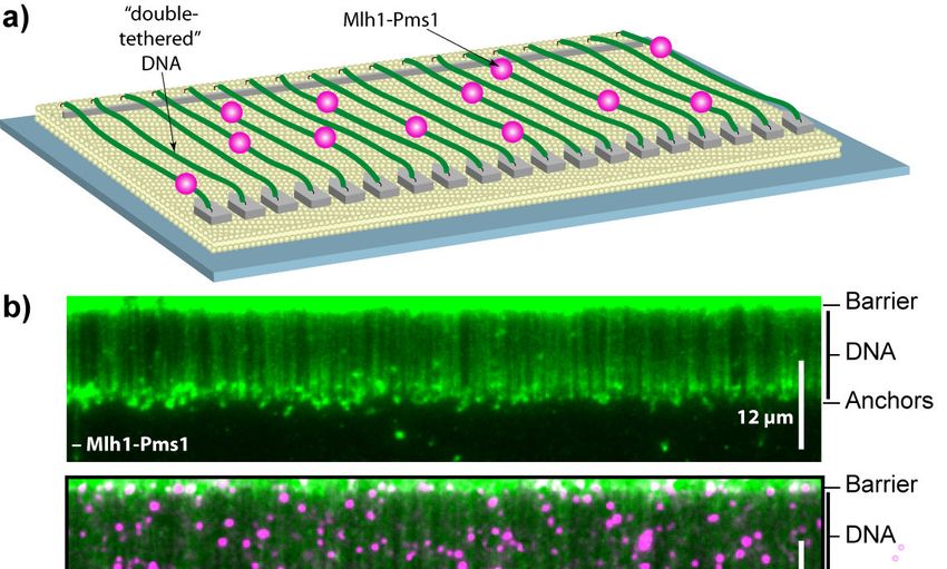
Microscopy: Science, Technology, Applications and Education
A. Méndez-Vilas and J. Díaz (Eds.)
______________________________________________

manually etched barriers on the slide surface. As a consequence, it is impossible to ensure efficient coverage of the
available viewing area, there are often problems with uneven alignment of DNA, and poor-quality barriers can also lead
to nonspecific surface adsorption of proteins, which can compromise experiments [14]. Manually etched barriers can
also alter the quality of the optical surface, and barriers that are too wide or too deep can lead to problems with light
scattering, making data collection and analysis difficult [14].

          3.3    Nanofabricated DNA curtains
To overcome the limitations of manually etched barriers we developed new barriers that are made by nanolithography
(Fig. 3B & 3C) [9-11, 14]. Our first generation of nanopatterned barriers consist of simple interlocking patterns of U-
shaped brackets [11]. The barriers oriented parallel to the direction of buffer flow form channels, which guide the DNA
molecules to barriers that are oriented perpendicular to the direction of buffer flow. The DNA molecules line up along
these perpendicular barriers, which we referr to as “nanoscale curtain rods”, to form DNA curtains (Fig. 4A) [11].
    Nanofabricated barrier patterns can be made by either electron-beam (ebeam) or nanoimprint lithography, and yield
uniform barrier patterns of high quality with nanometer precision [9, 11]. Ebeam lithography is inherently lower-
throughput because the beam must raster through each pattern individually, but is ideal for prototyping patterns prior to
settling on a specific design. Each flowcell can be reused a number of times, so in a typical laboratory, ebeam generated
slides are sufficient to fill most needs. Once a process is established, nanoimprint lithography is inherently faster and
easier than ebeam lithography, and personnel can learn and practice the entire process in less than a day. Nanoimprint
lithography must be optimized to minimize pattern distortion. Nevertheless, nanoimprint lithography offers the potential
for large-scale slide manufacture.

                                                                                   Fig. 2 General strategy for curtain
                                                                                   assembly. a) Lipid vesicles are
                                                                                   deposited on the fused silica surface
                                                                                   of a flowcell. b) The vesicles rupture
                                                                                   and fuse, forming a lipid bilayer that
                                                                                   spreads across the surface, but is
                                                                                   unable to diffuse across a physical
                                                                                   barrier. c) Biotinylated DNA is
                                                                                   tethered to the bilayer through a
                                                                                   biotin-strepavidin     linkage.     d)
                                                                                   Tethered DNA aligns against a
                                                                                   diffusion barrier and is extended to

    For ebeam lithography (Fig. 3B) the microscope slide is first coated with a thin polymer film (a bilayer of
polymethylmethacrylate (PMMA), followed by a layer of Aquasave conducting polymer), and then an electron beam is
used to “burn” a desired pattern into the polymer film and expose the underlying slide surface. Once the pattern is
generated, metal (we typically use chromium) is vaporized under vacuum and deposited over the entire surface. The
remaining polymer is then peeled away in a process called “lift-off”, leaving behind the metal pattern on the microscope
slide.
    Nanoimprinting is conceptually similar to ebeam lithography with the exception that a master with a positive relief
of the desired pattern is used to “stamp” the pattern into a PMMA monolayer coating the slide surface (Fig. 3C). The
masters themselves are fabricated using ebeam lithography, liftoff, and inductively-coupled plasma etching, and each
master can be used to print numerous slides. Once the patterns are stamped, the master is removed and the slides are put
through a process called descum to remove any remaining PMMA from the pattern. Metal is then vapor deposited on
the surface, and the PMMA is lifted off leaving behind the nanopatterned slide.
    While manually etched barriers are simple, they suffer from a number of drawbacks that can limit their potential.
These problems are all solved through the use of nanofabricated barriers that offer precisely designed patterns
positioned at defined locations, which do not present any optical aberrations and are capable of making full use of the
available surface area of the slide. Nanofabricated barriers increase the number of DNA molecules visible in one field
of view by an order of magnitude and can be used to design patterns suited to the needs of many types of experiments.
Moreover, the nanopatterned slides may be cleaned and reused many times with no noticeable decrease in surface
quality. The only disadvantage of nanofabricated barriers is that their construction requires access to a dedicated
nanofabrication facility and experience with the fabrication techniques.

724                                                           ©FORMATEX 2010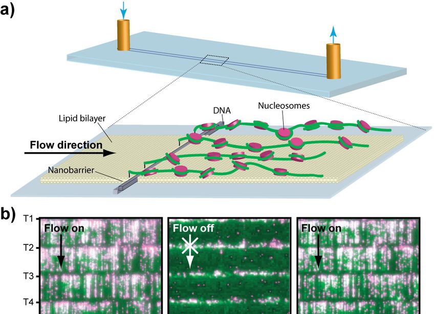
Microscopy: Science, Technology, Applications and Education
                                                                                                     A. Méndez-Vilas and J. Díaz (Eds.)
                                                                           ______________________________________________

         Fig. 3 Barrier fabrication methods. Simplified diagrams for making barriers by manual etching a), ebeam lithography
         b), or nanoimprint lithography c). For manual etching a), the slide is scratched with a diamond tipped drill bit. For
         ebeam lithography b), the slide is coated with PMMA, and a layer of Aquasave, and an electron beam is used to etch
         through these layers creating a pattern that defines the shapes of the diffusion barriers. Chromium (Cr) is deposited on
         the entire surface, and the remaining PMMA is lifted off, leaving behind the nanofabricated barriers. With
         nanoimprint lithography c), a master in pressed into the PMMA at high temperature under vacuum to create the
         desired pattern. The master is removed, residual PMMA is removed through a process called descum, metal is
         deposited on the entire surface, and remaining PMMA is lifted away, yielding nanofabricated metallic barriers.

         3.4   Using barrier geometry to control DNA organization
Our first generation of nanofabricated patterns were based upon linear barrier elements and offered a level of precision
unobtainable with manually etched barriers [11]. However, these nanofabricated linear barriers suffer from some
potential limitations. For example, the DNA molecules can overlap with one another, particularly at high DNA
densities, and the overlapping signals from multiple molecules can comprise data analysis. In addition, DNA molecules
aligned along linear barriers can slip slowly along the barrier edges, which is a problem when working with short DNA
molecules or when making measurements over relatively long time scales. These problems were solved with the
development of barriers shaped like a sawtooth pattern, and we refer to each tooth within the pattern as a geometric
nanowell because a single molecule of DNA can be loaded into each of these barrier features (Fig. 4B) [9]. These
sawtooth patterns completely eliminate any lateral slippage of DNA molecules along the barriers edges and can be
utilized effectively in experiments requiring observations over long periods of time. Importantly, the peak-to-peak
distance between the adjacent nanowells dictates the lateral separation of the DNA molecules that make up the curtain
[9].
    As with the linear barriers, the number of DNA molecules that make up the curtains can be varied by modulating
several different parameters, the simplest of which is the amount of DNA injected into the sample chamber. At high
concentrations multiple molecules of DNA can accumulate within each nanowell. To avoid this problem these
experiments can be conducted with a relatively small amount of DNA (determined empirically), such that less than one
DNA molecule is expected per nanowell. This ensures that some of the nanowells will remain unoccupied, many of the
wells will have a single DNA molecule, and some of the wells will have multiple DNA molecules. The exact number of
DNA molecules per nanowell can be determined by visual inspection, and confirmed by measuring the fluorescence
intensity of the DNA in each well [9]. Nanowells harboring two molecules are twice as bright as those harboring just
one, therefore allowing for easy discrimination of those with individual DNA molecules [9].

                                                        ©FORMATEX 2010                                                              725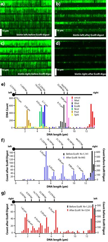
Microscopy: Science, Technology, Applications and Education
A. Méndez-Vilas and J. Díaz (Eds.)
______________________________________________

                                                                                     Fig. 4 Schematic of different
                                                                                     barrier and DNA curtain designs. a)
                                                                                     A simple linear barrier for aligning
                                                                                     DNA molecules. b) A sawtooth
                                                                                     barrier pattern where each tooth is
                                                                                     referred to as a geometric nanowell,
                                                                                     because the barrier geometry can
                                                                                     be used to control the precise
                                                                                     placement      of    single     DNA
                                                                                     molecules. c) A double-tethered
                                                                                     DNA curtain design comprised of
                                                                                     two distinct pattern elements. The
                                                                                     linear barriers are used to align the
                                                                                     lipid-tethered DNA molecules, and
                                                                                     the pentagons are coated with
                                                                                     antibodies and provide immobile
                                                                                     anchor points that can capture the
                                                                                     free ends of the DNA.

Relatively simple variations in pattern geometry allow for controlled manipulation of DNA molecules. The ability to
fabricate new patterns designed to suit a vast array of conceivable experimental ends gives the researcher a powerful
tool for investigating DNA-protein interactions with TIRFM.

          3.5    Double-tethered DNA curtains
We refer to all of the DNA curtains described above as “single-tethered” because they use linear DNA molecules
tethered to the lipid bilayer by just one end. The second end of each DNA is not anchored to the surface, therefore the
molecules quickly diffuse outside of the detection volume defined by the penetration depth of the evanescent field when
the buffer flow is turned off (Fig. 5B). This response to transient pauses in buffer flow is often used as a control to
verify that neither the DNA nor the proteins are nonspecifically stuck to the lipid bilayer (see below). However, when
the proteins of interest are affected by the hydrodynamic force, or when reagents are limiting and cannot be continually
injected into the flowcell, it is advantageous to be able to view DNA in the absence of buffer flow. Therefore, as an
alternative approach we developed “double-tethered” DNA curtains where both ends of the DNA are linked to the
surface, eliminating the need for continuous buffer flow (Fig. 4C) [10].
    Double-tethered curtains utilize two pattern elements: linear barriers to lipid diffusion and antibody-coated
pentagons that serve as immobile anchor points for attachment of the second end of the DNA [10]. The pentagons are
positioned at a fixed distance downstream from linear barriers and are separated from one another by small channels
that help prevent DNA from accumulating at the leading edge of the pentagons. The distance between the linear barriers
and the pentagons is optimized for the length of the DNA to be used for the experiments. The pentagons are coated with
antibodies directed against a small hapten, such as digoxigenin (DIG) or fluorescein isothiocyanate (FITC), which is
covalently linked to the ends of the DNA opposite the ends bearing the biotin tag [10]. When the hapten-coupled DNA
ends encounter the antibody-coated pentagons they become immobilized, and the DNA remains stretched parallel to the
surface even when no buffer is being pushed through the sample chamber. Flow can then be terminated and the
anchored DNA molecules are imaged by TIRFM.
    Previously, our studies of double-tethered DNA molecules relied on neutravidin stuck randomly to the slide surface
[15, 20]. After nonspecifically binding neutravidin to the surface, a lipid bilayer was formed as described above. Then,
DNA molecules biotinylated at both ends would be injected into the flowcell [20]. In these experiments, obtaining
statistically relevant data was extremely time consuming and the orientation of the DNA molecules was unknown.
Nanofabricated barriers for anchoring both ends of the DNA significantly increased throughput and enabled the study of
many proteins bound to parallel DNA molecules in the absence of buffer flow. These “double-tethered” experiments
have proven useful for the study of many diffusion proteins, such as those described in section 5.2.

726                                                           ©FORMATEX 2010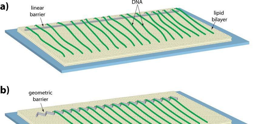
Microscopy: Science, Technology, Applications and Education
                                                                                                 A. Méndez-Vilas and J. Díaz (Eds.)
                                                                       ______________________________________________

         4. Quantum Dots as Protein Labels
We use nanocrystals, also called quantum dots (QDs) or Qdots, to fluorescently tag proteins [13, 21-24]. QDs offer a
number of advantages over more traditional organic fluorophores: they are commercially available, relatively small
(typically ~10-20 nanometers in diameter), extremely bright and photostable, and they have a very broad excitation
spectra such that a single laser source can be used to excite different colored QDs, eliminating the need for multiple
illumination sources during applications requiring multi-color imaging. Additionally, QDs have a narrow emission
spectra, enabling the separation of different colors by an image splitter, and the wavelength of light emitted is directly
related to the size of the QD. Moreover, it is fairly easy to tag the protein of interest by using a labelling strategy in
which recombinant proteins are expressed as fusions with an epitope tag (e.g. HA, FLAG, thioredoxin, etc.). These tags
are used as handles for conjugating the protein of interest to a QD that is covalently coupled to the corresponding
antibody.
    For most applications we use amine reactive QDs provided with an antibody conjugation kit from Invitrogen. The
amines can be coupled to any antibody using the hetero-bifunctional chemical crosslinking reagent SMCC
(succinimidyl 4-[N-maleimidomethyl]cyclohexane-1-carboxylate). According to the manufacturer this procedure yields
on the order of 1-3 antibodies per QD, although reports in the literature suggest values closer to 0.06 - 0.09 antibodies
per QD [25], and our own experimental measurements agree with these values (H.N.W. and E.C.G., unpublished). The
resulting conjugates can be purified by gel filtration chromatography to remove unreacted antibodies, and then be stored
in PBS (phosphate buffered saline; pH 7.4) at 4˚C for several weeks. For tagging proteins, the antibody-labeled QDs are
mixed with the epitope-tagged recombinant protein of interest, and incubated for a brief period on ice, and then the
entire mixture can be injected into the sample chamber containing a DNA curtain. Alternatively, unlabeled proteins can
be pre-bound to the DNA curtains, and then labeled in situ by injecting the antibody-coupled QDs into the flowcell.
Either of these labeling strategies can be applied to virtually any protein that has an epitope tag and is unaffected by the
attachment of the QD.
    Proteins of interest can also be expressed as fusion constructs bearing a small peptide sequence derived from biotin
carboxyl carrier protein (BCCP) that is biotinylated in vivo, and then the purified proteins can be labeled with
commercially available streptavidin-coated QDs. While there are a number of clear advantages to QDs, the primary
disadvantage of quantum dots is that they are not as small as organic fluorophores, and because of this it is critical to
assess the effect of the quantum dot on the biochemical properties of any protein under investigation through the use of
standard in vitro bulk biochemical assays.

         5. Examples of Experimental Applications
Our primary motivation for developing DNA curtains was for use in single molecule imaging of protein-DNA
interactions, and this approach is particularly well suited for measuring protein binding site distributions and studying
the real-time dynamic behavior of proteins as they move along DNA. Below we present brief examples of protein-DNA
interactions that we have begun exploring using our DNA curtain approach. For more specific details regarding any
these experiments, we refer the reader to several publications [15, 18-20, 26-28]. In addition to protein-DNA
interactions, this DNA curtain technology offers some potential advantages for optical mapping of DNA molecules
[29], and we have provided initial proof-of-concept experiments demonstrating this utility [9, 11].

         5.1   Chromatin Biology
Eukaryotic DNA is packaged into chromatin, which achieves the astounding feat of compacting nearly two meters of
genomic DNA into a volume of less than a cubic micron, and profoundly influences gene expression, gene silencing,
DNA repair and replication [30-34]. This extensive compaction is accomplished by nucleosomes, which are
nucleoprotein complexes ~10-nanometers in diameter and consist of an octamer of the four histone proteins H2A, H2B,
H3 and H4 (two copies of each histone are present) plus ~146-bp of highly bent DNA. The fundamental physical
interactions between the histone octamer and DNA play crucial roles in modulating chromatin structure, which in turn
has a profound impact on gene regulation.
   We have established a system for observing QD-tagged nucleosomes bound to DNA within curtains (Fig. 5) [26]. In
our first study we demonstrated that recent theoretical models could predict intrinsic, thermodynamically determined
positioning landscapes for nucleosomes deposited via stepped salt dialysis onto both λ-DNA and a 23kb PCR fragment
derived from the human β-globin locus. These studies have also confirmed that poly(dA-dT) tracts exclude
nucleosomes, and that the effects of these exclusionary sequences dominate the intrinsic binding landscape. We have
shown that the deposition pattern for the human β-globin locus suggests an organizational mechanism consistent with a
small number of strongly positioned nucleosomes near promoter and regulatory regions, and a statistical packing of
other nucleosomes throughout the locus. Finally, using this DNA curtains approach we have been able to demonstrate

                                                     ©FORMATEX 2010                                                            727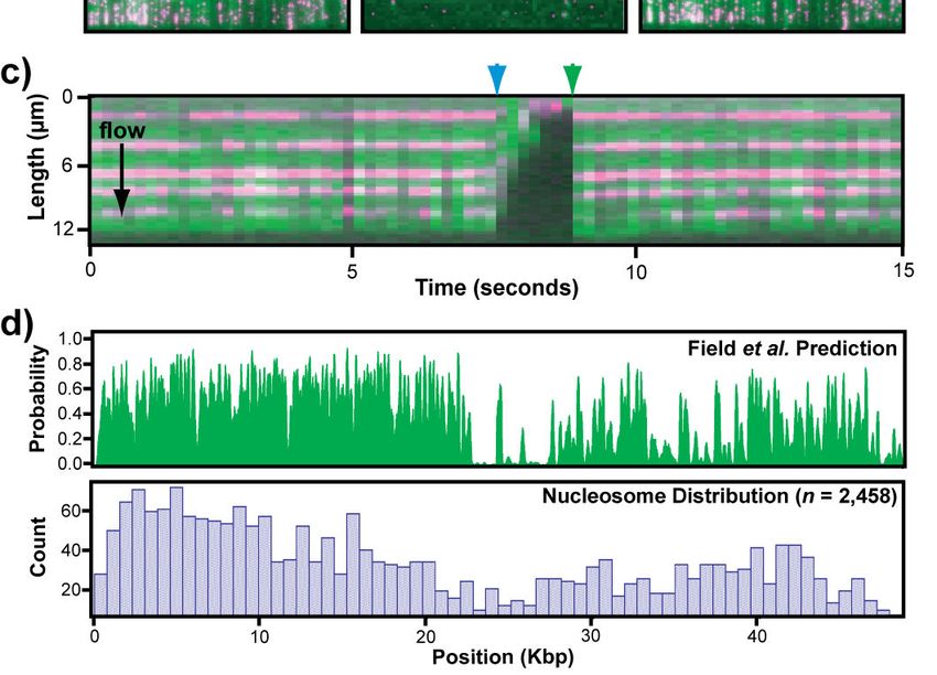
Microscopy: Science, Technology, Applications and Education
A. Méndez-Vilas and J. Díaz (Eds.)
______________________________________________

that octameric nucleosomes harboring a centromere-specific variant of histone H3 (CenH3) display intrinsic deposition
patterns nearly identical to canonical nucleosomes. In contrast, hexameric nucleosomes harboring both CenH3 and
Scm3, a centromer-specific nonhistone protein, overcome the exclusionary affects of poly(dA-dT), which allows them
to be deposited in regions that disfavor normal nucleosome octamers. This initial work with nucleosomes on the DNA
curtains now sets the stage for beginning to study how other proteins interact with and influence nucleosomes and
higher-order chromatin structures.

                                                                               Fig. 5 Visualizing proteins bound to a
                                                                               DNA        curtain.   a)   Schematic     of
                                                                               experimental setup with a single tethered
                                                                               DNA curtain. Nucleosomes (shown in
                                                                               magenta) bound to DNA (shown in green)
                                                                               that is aligned along a nanobarrier. b) The
                                                                               left panel shows an image of nucleosomes
                                                                               bound to a single-tethered DNA curtain in
                                                                               the presence of buffer flow, the middle
                                                                               panel shows the same field of view after
                                                                               transiently pausing buffer flow, and the
                                                                               right panel shows the field of view after
                                                                               resumption of flow. A kymogram
                                                                               illustrating five nucleosomes on one DNA
                                                                               molecule is shown in c). The nucleosomes
                                                                               disappear when flow is temporarily
                                                                               interrupted (blue arrowhead), and reappear
                                                                               when flow is resumed (green arrowhead),
                                                                               verifying they are bound to the DNA and
                                                                               do not interact with the lipid bilayer. The
                                                                               top panel in d) shows the theoretical
                                                                               distribution of nucleosomes, and the lower
                                                                               panel shows the observed distribution of
                                                                               nucleosomes obtained from DNA curtain
                                                                               experiments.

Chromatin is organized and controlled by a class of proteins
collectively referred to as “chromatin remodelers”, many of which are ATP-dependent molecular motors capable of
pushing and/or ejecting nucleosomes [30, 31]. Despite the importance of these chromatin-remodeling proteins,
relatively little is known about how they actually function. Using DNA curtain assays, we have begun to study the
dynamics of ATP-dependent chromatin remodeling proteins [18]. Rdh54 is an Snf2-family member, and is involved in
meiotic and mitotic homologous DNA recombination in S. cerevisiae. Rdh54 is also capable of remodeling
nucleosomes, and this activity may be related to its involvement in DNA recombination. Our studies demonstrated that
Rdh54 is an ATP-dependent translocase that generates looped DNA structures. Rdh54 traveled at a mean velocity of 80
base pairs per second, but individual proteins were able to change direction and/or velocity, or even pause as they
moved along the DNA. Similar behaviors have been reported in a separate single-molecule study from
Kowalczykowski and colleagues [35, 36], confirming our observations. These findings suggest that this family of DNA
translocases may have multiple motor domains within a single multimeric protein complex, and the pauses, velocity and
direction changes may reflect the protein complex engaging different motor domains with the DNA. As this work
proceeds we are now in a position to begin asking how Rdh54 and other DNA translocases behave when they encounter
nucleosomes.
   Although all of these studies are still in their infancy, it is clear that the DNA curtain strategy can offer a number of
unique insights into chromatin and chromatin biology that cannot be obtained through more traditional biochemical and
biophysical approaches. Future studies can now begin probing more complex chromatin structures, such as chromatin
composed of nucleosomes containing modified histones or histone variants, as well as the interactions between
chromatin remodeling proteins and these varied substrates.

728                                                           ©FORMATEX 2010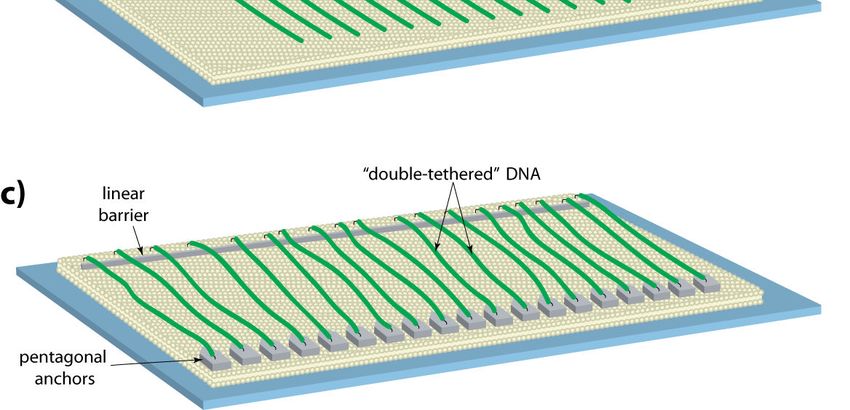
Microscopy: Science, Technology, Applications and Education
                                                                                              A. Méndez-Vilas and J. Díaz (Eds.)
                                                                    ______________________________________________

         5.2   Facilitated Diffusion and Mismatch Repair
Most DNA-binding proteins are thought to move throughout the eukaryotic nucleus using some form of facilitated
diffusion (e.g. hopping, sliding, jumping, or intersegmental transfer) [37, 38]. We study facilitated diffusion using
post-replicative mismatch repair (MMR) proteins as a model system [20, 39, 40]. MMR is necessary for correcting
errors made during DNA synthesis. In eukaryotes, the protein complex Msh2-Msh6 is responsible for locating and
initiating repair of mispaired bases, and works in concert with Mlh1-Pms1, which coordinates downstream steps in the
repair pathway. Using anti-HA QDs, and HA-tagged Msh2-Msh6, we have demonstrated that Msh2-Msh6 can travel
along DNA by 1D-diffusion, and the protein appears to track the phosphate backbone as it slides in 1D along the DNA
[20]. Msh2-Msh6 also reversibly enters a nondiffusive state and we believe that this occurs when the protein stops to
interrogate a DNA site to determine whether or not it is damaged. The addition of ATP caused the nondiffusive Msh2-
Msh6 to reenter a diffusive state and continue sliding along the DNA and we hypothesize that reentry into a diffusive

 Fig.     6    Visualizing    protein
 movement on DNA curtains. a)
 Schematic of the experimental setup
 with a double tethered DNA curtain.
 Mlh1-Pms1 (shown in magenta)
 bound to DNA (green) aligned and
 anchored in a double-tethered
 curtain. b) The upper panel shows
 the DNA only, before injection of
 Mlh1-Pms1, and the lower panel
 shows the same field of view after
 injection of QD-tagged Mlh1-Pms1.
 c) Shows kymograms of Mlh1-
 Pms1 moving along the DNA by 1-
 dimensional diffusion via a hopping
 mechanism. In the lower panel, the
 red arrowhead indicates the
 occurrence of a DNA break, which
 causes the DNA and protein to
 disappear from view as the diffuse
 up and out of the evanescent field.
 d) Kymogram shows an example of
 Mlh1-Pms1         hopping       past
 nucleosomes (green) as it moves
 along the DNA.

state that mimics what occurs after lesion recognition, and represents the functional consequence of a conformational
change that is triggered by ATP binding. Using double-tethered DNA curtains (Fig. 6A & 6B), we have also shown
that Mlh1-Pms1 can bind DNA and that it can travel along the DNA helix by 1D diffusion (Fig. 6C) [40]. Contrary to
Msh2-Msh6, Mlh1-Pms1 utilizes a hopping or stepping mechanism, and also displays behaviors consistent with a
model in which the protein complex is wrapped around the DNA in a ring-like configuration.
    Most DNA-binding proteins cannot mechanically disrupt nucleosomes, therefore other mechanisms must come into
play if these proteins are to scan chromatin [41, 42]. Whether or not proteins can circumnavigate nucleosomes without
dissociating from DNA remains an unresolved issue with direct bearing on how all eukaryotic DNA-binding proteins
are trafficked throughout the nucleus [41-43]. This problem led us to ask whether eukaryotic proteins that diffuse in 1D
along DNA could bypass individual nucleosomes and travel along nucleosomal arrays, and if so, what mechanistic
principles affect mobility along chromatin [40]. As indicated above, Msh2-Msh6 slides on DNA, whereas Mlh1-Pms1
travels in 1D along DNA via a hopping mechanism. An important functional consequence of this mechanistic difference
is that Mlh1-Pms1 can diffuse past nucleosomes and travel along chromatin, whereas Msh2-Msh6 cannot. The
functional consequences of these mechanistic differences are that Mlh1-Pms1 can readily traverse nucleosomes and
travel along chromatin whereas Msh2-Msh6 cannot (Fig. 6D) [40]. These results demonstrate that 1D diffusion can
occur on crowded DNA substrates in the presence of protein obstacles, and that the ability to bypass obstacles is
dependent upon the diffusion mechanism employed by the protein in question. We anticipate that these behaviors
displayed by Mlh1-Pms1 and Msh2-Msh6 in response to collisions with nucleosomes will reflect general mechanistic
attributes of their respective modes of 1D-diffusion, which in principle will apply to any proteins that diffuse on DNA
(e.g. DNA repair proteins, transcription factors, etc.): proteins that track the phosphate backbone while sliding along
DNA will experience a barrier upon encountering obstacles and must either disengage the DNA and enter a 2D- or 3D-

                                                   ©FORMATEX 2010                                                           729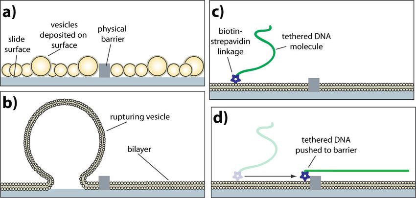
Microscopy: Science, Technology, Applications and Education
A. Méndez-Vilas and J. Díaz (Eds.)
______________________________________________

mode of diffusion to continue searching for targets, or the DNA must be cleared of obstacles before hand to allow
unhindered access to the DNA; in contrast, proteins that do not track the backbone can traverse obstacles without
experiencing significant boundary effects. This finding has important implications for the intranuclear trafficking of
virtually all DNA binding proteins, as it implies that proteins that travel by hopping or stepping along DNA will be able
to bypass nucleosome obstructions, but proteins that slide on DNA will not.

                                                                       Fig. 7 Optical DNA mapping. A curtain of λ-DNA tethered
                                                                       by the left ends of the molecules is shown before a) and after
                                                                       b) complete digestion with EcoRI, which yields a ~21 kb
                                                                       tethered product. Panels c) and d) show λ-DNA tethered by
                                                                       the right ends before and after digestion with EcoRI, which
                                                                       is expected to yield a 3.5 kb tethered product. The images
                                                                       and histograms in panel e) show the length distributions
                                                                       (measured from the barrier edge to the end of the DNA) of
                                                                       uncut λ-DNA tethered via the left end following a series of
                                                                       successive digests with Nhe I, Xho I, EcoRI, Nco I, Pvu I,
                                                                       and Sph I. The histograms in f) and g) show the results of
                                                                       partial EcoRI digests with λ-DNA tethered by either the left
                                                                       or right ends, respectively. Fragments outside the peak
                                                                       values were due to either laser induced double-stranded
                                                                       breaks of the YOYO1 stained DNA or uncut DNA
                                                                       molecules.

          5.3    DNA Optical Mapping
Although our primary intent was to generate new tools that facilitate massively parallel data collection for single
molecule analysis of protein-DNA interactions, it is also apparent that the DNA curtains offer a myriad of other
potential applications. For example, optical restriction mapping has evolved into a powerful technique for the physical
analysis of large DNA molecules [44-46], and because the DNA curtains are organized with all of the molecules in a
defined orientation they provide a simple platform for mapping the locations of specific restriction sites. Different
combinations of restriction sites can be easily mapped within the DNA curtain by successive use of the desired enzymes
(Fig. 7). In this example, the curtain was sequentially cut with the restriction enzymes NheI, XhoI, EcoRI, NcoI, PvuI,
and SphI, and the observed lengths (µm) of the DNA fragments were measured and plotted as a histogram. As shown
here, complete restriction digests leave behind tethered DNA fragments whose lengths correspond to the cleavage site

730                                                           ©FORMATEX 2010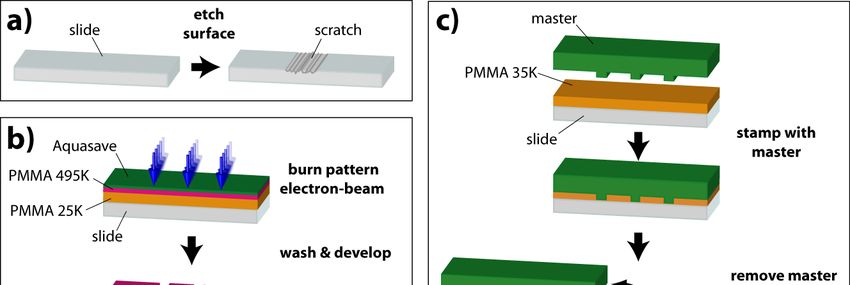
Microscopy: Science, Technology, Applications and Education
                                                                                                  A. Méndez-Vilas and J. Díaz (Eds.)
                                                                        ______________________________________________

closest to the biotinylated ends of the DNA, and any other downstream fragments are washed away. Complete
restriction digests can reveal single cleavage sites, and can not map multiple, identical restriction sites throughout the
DNA molecules. In contrast, a partial digest should yield a population of discrete fragments whose lengths correspond
to each of the restriction sites present in the DNA molecules. To verify this prediction, we performed a partial EcoRI
digest of curtains made with DNA molecules that were tethered by either the right or the left ends. The lengths of the
resulting fragments were then measured and their distributions plotted as histograms. This partial digest strategy was
sufficient to identify all five EcoRI sites within the phage λ genome. Together these experiments demonstrate that the
locations of restriction sites within large molecules can be rapidly identified via optical mapping of the DNA curtains.
Moreover, because these reactions are performed within a microfluidic sample chamber and DNA is only anchored by
one end, collection of the liberated fragments in sufficient quantities for cloning and further analysis should prove
straightforward.

           6. Summary & Future Directions
We have developed a novel technique called DNA curtains that can serve as a powerful and flexible tool for single
molecule imaging of protein-nucleic acid interactions. DNA curtains can be made with either microfabricated barriers
or nanofabricated barriers to lipid diffusion, and they enable simultaneous visualization of hundreds of long, parallel
DNA molecules in real time in a flexible experimental format that can be readily applied to a variety of problems.
Nanofabricated barrier patterns offers tremendous reproducibility, accuracy, design flexibility, and are particularly
advantageous for prototyping devices. With these tools we can visualize thousands of individual, perfectly aligned DNA
molecules, all arranged in the exact same orientation using TIRFM. The primary advantages of our approach are that we
can observe specifically labelled proteins bound to DNA, record their position, track their movement, and observe how
these proteins interact with each other and with DNA.

Acknowledgements The authors thank members of the Greene laboratory for useful discussions and critical reading of the
manuscript. The Greene laboratory is funded by research grants from the National Institutes of Health and the National Science
Foundation. E.C.G. is an Early Career Scientist for the Howard Hughes Medical Institute.

           References
[1]    Bai, L., et al., Cell, 2007. 129(7): p. 1299 - 309.
[2]    Galletto, R., et al., Nature, 2006. 443(7113): p. 875 - 8.
[3]    Joo, C., et al., Cell, 2006. 126(3): p. 515 - 27.
[4]    Zlatanova, J. and K. van Holde, Mol Cell, 2006. 24(3): p. 317 - 29.
[5]    Hilario, J. and S. Kowalczykowski, Curr Opin Chem Biol. 14(1): p. 15 - 22.
[6]    van Oijen, A. and J. Loparo, Annu Rev Biophys. 39: p. 429 - 48.
[7]    Visnapuu, M.L., D. Duzdevich, and E.C. Greene, Mol Biosyst, 2008. 4(5): p. 394 - 403.
[8]    Granéli, A., et al., Langmuir, 2006. 22: p. 292-299.
[9]    Visnapuu, M.L., et al., Langmuir, 2008. 24(19): p. 11293 - 9.
[10]   Gorman, J., et al., Langmuir, 2010. 26: p. 1372 - 9.
[11]   Fazio, T., et al., Langmuir, 2008. 24(18): p. 10524 - 31.
[12]   Axelrod, D., Methods Cell Biol, 1989. 30: p. 245 - 70.
[13]   Visnapuu, M.-L., D. Duzdevich, and E.C. Greene, in Modern Research and Educational Topics in Microscopy, A. Méndez-
       Vilas and J. Díaz, Editors. 2007, Formatex. p. 297-308.
[14]   Greene, E.C., et al., in Methods in Enzymology, N.G. Walters, Editor. 2010, Academic Press. p. 293-315.
[15]   Granéli, A., et al., Proc Natl Acad Sci U S A, 2006. 103(5): p. 1221-1226.
[16]   Cremer, P.S. and S.G. Boxer, J. Phys. Chem. B, 1999. 103: p. 2554-2559.
[17]   Groves, J.T. and S.G. Boxer, Acc Chem Res, 2002. 35(3): p. 149 - 57.
[18]   Prasad, T.K., et al., J Mol Biol, 2007. 369(4): p. 940 - 53.
[19]   Prasad, T.K., C. Yeykal, and E.C. Greene, J Mol Biol, 2006. 363: p. 713-728.
[20]   Gorman, J., et al., Mol Cell, 2007. 28(3): p. 359 - 70.
[21]   Kaji, N., M. Tokeshi, and Y. Baba, Anal Sci, 2007. 23(1): p. 21 - 4.
[22]   Medintz, I., et al., Nat Mater, 2005. 4(6): p. 435 - 46.
[23]   Pinaud, F., et al., Nat Methods. 7(4): p. 275 - 85.
[24]   Pinaud, F., et al., Biomaterials, 2006. 27(9): p. 1679 - 87.
[25]   Pathak, S., M.C. Davidson, and G.A. Silva, Nano Letters, 2007. 7(7): p. 1839-1845.
[26]   Visnapuu, M.-L. and E. Greene, Nat Struct Mol Biol, 2009. 16: p. 1056-1062.
[27]   Robertson, R., et al., Proc Natl Acad Sci U S A, 2009. 106(31): p. 12688 - 93.
[28]   Robertson, R., et al., J Mol Biol, 2009. 388(4): p. 703 - 20.
[29]   Schwartz, D. and A. Samad, Curr Opin Biotechnol, 1997. 8(1): p. 70 - 4.
[30]   Cairns, B.R., Nat Struct Mol Biol, 2007. 14(11): p. 989 - 96.
[31]   Clapier, C. and B. Cairns, Annu Rev Biochem, 2009. 78: p. 273 - 304.
[32]   Groth, A., et al., Cell, 2007. 128: p. 721-733.

                                                      ©FORMATEX 2010                                                            731
Microscopy: Science, Technology, Applications and Education A. Méndez-Vilas and J. Díaz (Eds.) ______________________________________________ [33] Widom, J., Annu Rev Biophys Biomol Struct, 1998. 27: p. 285 - 327. [34] Zlatanova, J. and S.H. Leuba, J Mol Biol, 2003. 331(1): p. 1 - 19. [35] Nimonkar, A.V., et al., J Biol Chem, 2007. 282(42): p. 30776 - 84. [36] Amitani, I., R. Baskin, and S. Kowalczykowski, Mol Cell, 2006. 23(1): p. 143 - 8. [37] Gorman, J. and E.C. Greene, Nat Struct Mol Biol, 2008. 15: p. 768-774. [38] von Hippel, P. and O. Berg, J Biol Chem, 1989. 264(2): p. 675 - 8. [39] Kunkel, T.A. and D.A. Erie, Annu Rev Biochem, 2005. 74: p. 681 - 710. [40] Gorman, J., et al., Nat Struct Mol Biol, 2010. (In Press). [41] Gorski, S., M. Dundr, and T. Misteli, Curr Opin Cell Biol, 2006. 18(3): p. 284 - 90. [42] Hager, G., J. McNally, and T. Misteli, Mol Cell, 2009. 35(6): p. 741 - 53. [43] Mirny, L., et al., J Physics A, 2009. 42(43): p. 434013. [44] Dimalanta, E.T., et al., Analytical Chemistry, 2004. 76: p. 5293-5301. [45] Lin, J., et al., Science, 1999. 285: p. 1558-1562. [46] Schwartz, D.C., et al., Science, 1993. 262(5130): p. 110 - 4. 732 ©FORMATEX 2010
You can also read