Non-mag Spacing Requirements - Neil Bergstrom May 10, 2012 Edinburgh, Scotland 35th ISCWSA / SPE WPTS Conference
←
→
Page content transcription
If your browser does not render page correctly, please read the page content below

Non-mag Spacing Requirements
              Neil Bergstrom
    35th ISCWSA / SPE WPTS Conference
               May 10, 2012
            Edinburgh, Scotland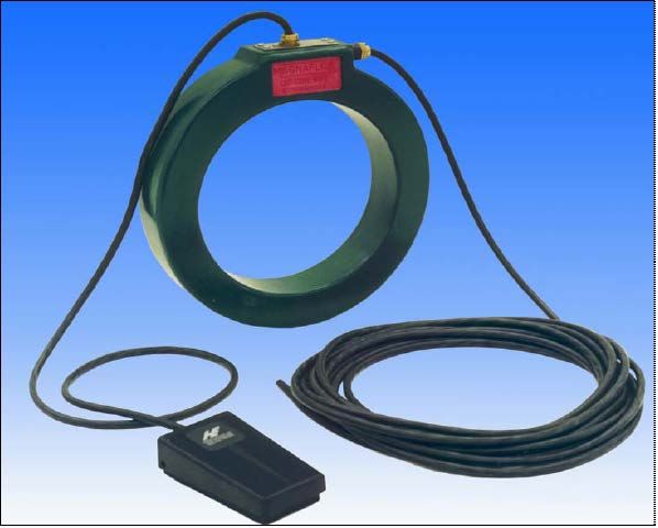
Disclaimer
• This presentation is based my personal
  observations and research over many years
  and does not represent an official position of
  my current or previous employers.
Safety Moment
Don’t forget your PPE
Major Error Sources for MWD
 • The two largest error contributors to magnetic
   MWD error ellipses are:
1. Magnetic North Reference terms

The reference field has been much discussed and improved by
better geomagnetic models, crustal corrections, and disturbance
correction monitoring.

2. Drillstring Interference (DSI) terms

 To account for the effects of magnetic interference from the BHA
Relative Size of Azimuth Error Sources
             Horizontal well in North Texas
         (azimuth ~ 20 degrees from due east VS 5650 ft)

•   Standard MWD.IPM 2 Sigma Ellipse ~ 150 x 42 ft.
•   Without North Ref terms ~ 128 x 42 feet
•   Without DSI or N Ref terms ~ 42 x 42 feet
•   Drillstring Interference terms are responsible for >
    50% of total lateral error.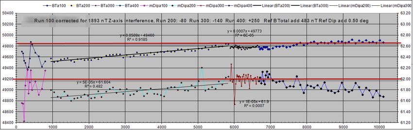
Azimuth error due to Drillstring
         Interference (DSI)
• Mostly in Z-axis (along-hole axis)
• Can be from below (motor, float, stabilizers)
• Or Above (HWDP, Collars, Filter sub, XO)
• DSI sources typically modeled as a monopole
  at the bottom of the non-mag collars, a
  monopole at the top of the non-mag, and a
  monopole at the bottom of the BHA.
• Sometimes the last two are omitted
  assuming they are much further from the
  MWD sensors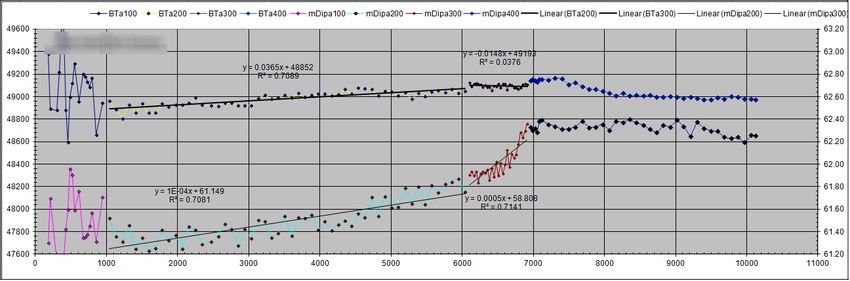
Reducing the error from DSI
• Increase non-mag spacing above and below
  – Expensive
  – Increases bit-sensor spacing (below only)
• Want measurements nearer the bit
  – $$$ to get near bit spacing / why not proportional?
• More non-mag components (stabilizers, floats,
  motor top subs, etc.
• Degauss steel components after MPI
  – Required by ASTM MPI Standard
  – Requires low frequency and/or high power coils
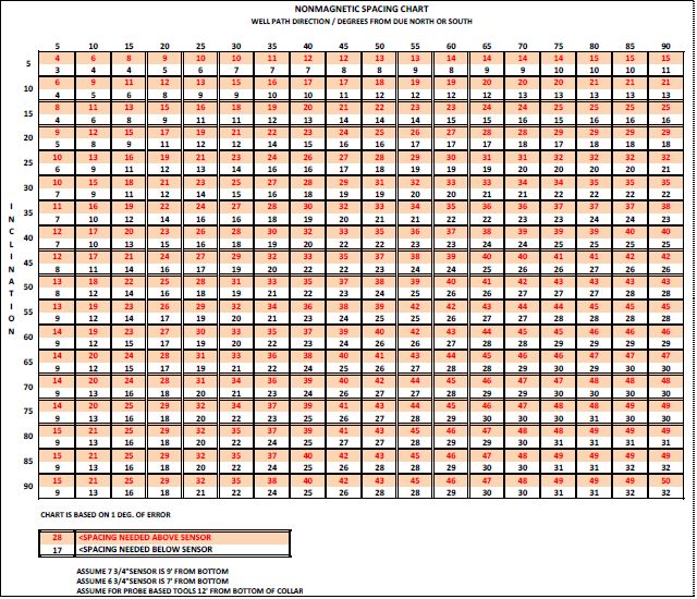
The Old Way (1980’s) – by Charts
The Old Way – By Table
How much error is allowable?
•   When using generic MWD coefficients
•   1 sigma error due to drillstring interference
•   Error = 0.25 + 0.6 sin(inc) * sin(azimuthmagnetic)
•   Worst case is horizontal E-W
•   RSS sum = sqrt(0.25^2 + 0.6^2) = 0.65 degrees
•   Other IPMs may use different coefficients
How much DSI is that?
• At Horizontal EW:
• Error = Asin(DSI/Bhorizontal)
• DSI = Bhorizontal*sin(error)
• Assume 0.65 deg error and 23,000 nT
  Bhorizontal (Midcon USA value)
• Allowable DSI = 261 nT
How to convert that to Spacing?
• Requires assumption of 1 sigma pole strengths
• Typical assumption ~ 500 uW at top of motor
   – May vary with BHA Size
   – Matching pole at bottom of BHA
   – Sign is unknown
• Typical assumption ~ 1000 uW at top of non-mag
   – Sign is usually + (north-seeking pole) in N. Hemisphere
• Interference = PoleStrength / (distance^2 *4pi)
   – PoleStrength in micro-Webers (uW) and distance in meters
     gives interference in micro-Tesla. (x1000 for nT)
• Add up contribution from each source
Is 500 uW at 1 sigma a good
assumption for pole strength?
• NO
• I’ve seen poles in excess of 2000 uW. In Steve
Grindrod’s 1989 paper he mentions a 3000 uW pole
on a turbine which was ignored as an outlier.
• With no further information I recommend using 1000
uW as a 1 sigma pole strength.
• That means LOTS MORE non-mag spacing.
Or eliminate the “hot” components from the BHAWhat to do about DSI? • Make sure there are no magnetically “Hot” parts in the BHA. • Degauss all parts. (more on this later) • Measure and record residual magnetism before and after each run. • Estimate pole strength from Z-axis correction and compare with pre and post run measurements.
Sources of BHA Magnetism
• Magnetic Inspection
• Mechanical stresses in the presence of high magnetic
  field. (such as sliding or rotating through magnetized
  casing)
• Induction due to magnetic susceptibility of the steel.
  This is a minor effect and shows up as a Bz scale
  factor error, not a bias.
• NOT typically due to drilling in the earth’s magnetic
  field of ~0.5 Oersted. Coercivity of steel is typically
  >>50 Oe.
Crude Estimate of Pole Strength
• 100 uW pole on a motor gives ~1 gauss at 6 inches.
• No gaussmeter? Does a paper clip stick?

 RB Annis Model 25: www.rbannis.com Available from McMaster-Carr
 as field strength indicators http://www.mcmaster.com/#magnetic-
 field-indicators/=h0643s I recommend -10-0-10 or -20-0-20 gauss.

 Magnetic Analysis Corporation: http://www.mac-
 ndt.com/index.php/technologies/magnetism-detectors/
How much is too much residual magnetism?
•   If using conventional estimates based on ~500 uW pole strength and
    generic MWD IPM, more than 5 gauss at 6” exceeds the 1 sigma assumed
    value (500 uW) – that’s before the trip in the hole.
•   ASTM E-1444 Standard Practice for Magnetic Particle Inspection:

Think 3 gauss is too tight a spec? Use 300,000 nT.
After proper degaussing you should not see the needle move
on a mechanical gaussmeter.
Z-axis and Cross Axis Interference • Most interference will be in Z-axis (long axis) • If the source of interference is close and cross- magnetized, Bx and By may be effected • This shows up as a bias in Bx and/or By • Cross-axis interference (bias) can be estimated and corrected using roll test or multi-station analysis.
Observations regarding residual magnetism
         (Northern Hemisphere)
• Drill pipe tends to be magnetized in the direction of
  the earth’s field with a +pole (north-seeking) at the
  bottom (pin) end.
• Motors and subs can be magnetized in either
  direction.
• Assembled steel parts act as a single magnetic
  conductor. External fields are only seen at
  discontinuities.
• Internal fields in the steel can’t be measured.
Ferromagnetic Domains
• Ferromagnetic materials have micron-scale magnetic domains
or “Weiss Domains”
• If the domains are predominately in one direction the
material is magnetized.
• The object of degaussing is to randomly orient the Weiss
domains so they cancel each other out.
• Pierre-Ernest Weiss (March 25, 1865 - October 24, 1940) was a French physicist
who developed the domain theory of ferromagnetism in 1907.DC Methods • In principle this is simple – just apply enough magnetic field to reverse half the domains. • In practice it is very difficult – the amount of field is unknown. • DC methods can leave strong internal fields which cannot be measured but will express themselves over time, especially with shock and vibration.
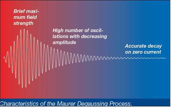
Degaussing Method - AC
                                           The work piece is passed slowly
                                           through an AC coil. In a strong field
                                           each Weiss domain is reversed with
                                           the AC magnetic field.

As each Weiss domain gets further from
the coil, the magnetic field strength is
reduced so fewer and fewer of the
domains are reversed in direction. The
end result is an approximately equal
number of domains magnetized in each
direction, for no net magnetization
Limitation of AC Method • Skin effect prevents sufficient magnetic field to randomize the domains from penetrating more than a few mm. • Skin Depth = 1/e ~ 37 % • AC Demagnetization at line frequency is superficial and temporary
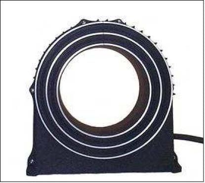
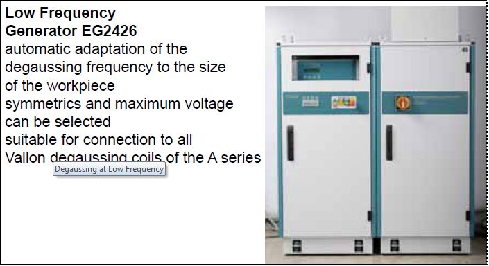
Degaussing at Low Frequency

Used with permission from Vallon http://www.vallon-
degaussing.com/pdf/EM-Degaussing-brochure_12_07.pdf
Magnaflux L10 portable coil
    Insufficient power to degauss large parts
Typically run at line frequency (50 or 60 Hz) or DC
Scanning Non-Mag Collars and parts • Non-magnetic properties are due to microstructure, not chemical composition. • It is possible for material to lose non-mag characteristics for example by cold working • What should be checked is whether the material CAN be magnetized, not whether it actually IS magnetized at the time of the test. • Non-Mag parts should be run through a magnetizing coil prior to the scan for magnetism. • If acceptable minor magnetism (for example at the tool joints) is found, the part should be degaussed before use. • Avoid locating MWD sensors near a tool joint
Vendor Contact
Vendor Contact
Check for degaussing
• For parts with a bored center:
• Put a magnetized test piece of the same
  material type in the bore. After degaussing it
  should not be magnetic.
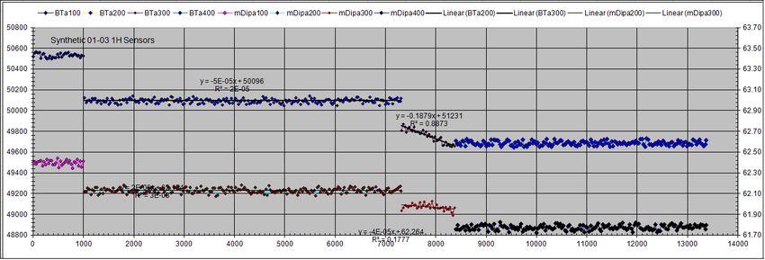
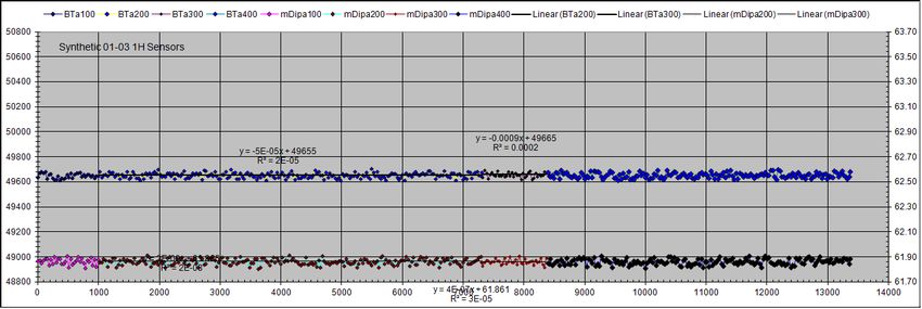
Example Synthetic Data
                         Planned Inc
                         and Azimuth

                         4 BHA Runs
                         DSI Run 1 =1000
                         DSI Run 2 = 500
                         DSI Run 3= 200
                         DSI Run 4 = -260

                         Corrected data
                         Btotal and Dip
                         are straight
                         lines and match
                         up
Example Raw Data Correction
Problem Dataset
Dip should be flat across curve
Recommendations
•   Degauss completely using low frequency AC. If there is measureable
    residual magnetism it is best to leave a + pole on the top end of the
    motor/stab/float to cancel some of the field from the + pole on the
    bottom of the drillpipe / collars.
•   Record pre and post run residual magnetism from major parts. (motor /
    float / stab / XO / filter sub / HWDP
•   Compare with calculated DSI from MWD sensor data.
•   Use at least 10 feet of non-mag spacing even when drilling N-S to avoid
    cross-axial errors and induced magnetism effects.
•   Use non-mag stabilizers and subs when possible.
•   BHA materials should NOT be low coercivity mild steel. Use either
     – Non-magnetic
     – High Coercivity (hard to magnetize and demagnetize)
•   Parts that contact steel casing should be non-mag
•   Assume 1000 uW poles unless any parts >5 gauss at 6” are eliminated.
    Then 500 uW poles are OK.
•   Collect statistics on pole strengths after degaussing to justify assumptions
    before using smaller values.
•   Plot Gtotal, Btotal, and Dip angles vs measured depth and look for trends.
Questions and Comments?
You can also read