OPERATION MANUAL - AF INTEGRA / AF-H INTEGRA ELT
←
→
Page content transcription
If your browser does not render page correctly, please read the page content below
DOC09078G

                                                                Emergency Locator Transmitters
                                                                        Orolia S.A.S.

                                                                               OPERATION MANUAL
© 2021 OROLIA S.A.S. ALL RIGHTS ARE STRICTLY RESERVED.

                                                                  AF INTEGRA / AF-H INTEGRA ELT
                                                               With built-in GPS & built-in back-up Antenna

                                                         Revision 06                                         TP PAGE : 1
                                                         First issue: OCT 20/2010                Date of rev.: SEP 03/2021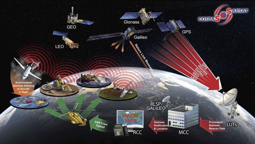
Users are kindly requested to notify Orolia S.A.S of any
           discrepancy, omission or error found in this manual.
                  Please report to our customer support:
                       E-mail: support@orolia.com
                         Tel.: +33 (0)2 97 02 49 00

This document is copyright © 2021 OROLIA S.A.S. All rights are strictly
reserved. This document and any attached materials contains proprietary
and confidential information and data and is the sole property of Orolia®
group and/or its affiliates.
The documents, any attached materials and/or information contained the-
rein must not be used, disseminated, or distributed except for the agreed
purpose. unauthorized use, reproduction, or issue to any third party is not
permitted without the prior written consent of the orolia group. This docu-
ment is to be returned to the orolia group when the agreed purpose is ful-
filled.

© 2021 Orolia S.A.S. All rigths are strictly reserved.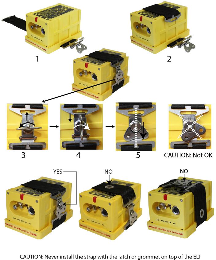
OPERATION MANUAL
                                                         AF INTEGRA / AF-H INTEGRA ELT

                                  RECORD OF REVISIONS

        REV. Nb REVISION DATE                                  INSERTION DATE            BY
        00               OCT 20/2010                           OCT 20/2010               J.S.
        01               MAY 09/2011                           MAY 09/2011               J.S.
        02               JAN 31/2012                           JAN 31/2012               J.S.
        03               JUN 20/2013                           JUN 20/2013               J.S.
        04               NOV 02/2015                           NOV 02/2015               J.S.
        05               MAY 15/2019                           MAY 15/2019               C.L.G.
        06               SEP 03/2021                           SEP 03/2021               C.L.G.

                                                                                         ROR PAGE: 1
© 2021 Orolia S.A.S. All rigths are strictly reserved.
                                                                                          SEP 03/2021
OPERATION MANUAL
                                                         AF INTEGRA / AF-H INTEGRA ELT

                                         RECORD OF REVISIONS

                              PAGE INTENTIONALLY LEFT BLANK

                                                                                         ROR PAGE: 2
© 2021 Orolia S.A.S. All rigths are strictly reserved.
                                                                                          SEP 03/2021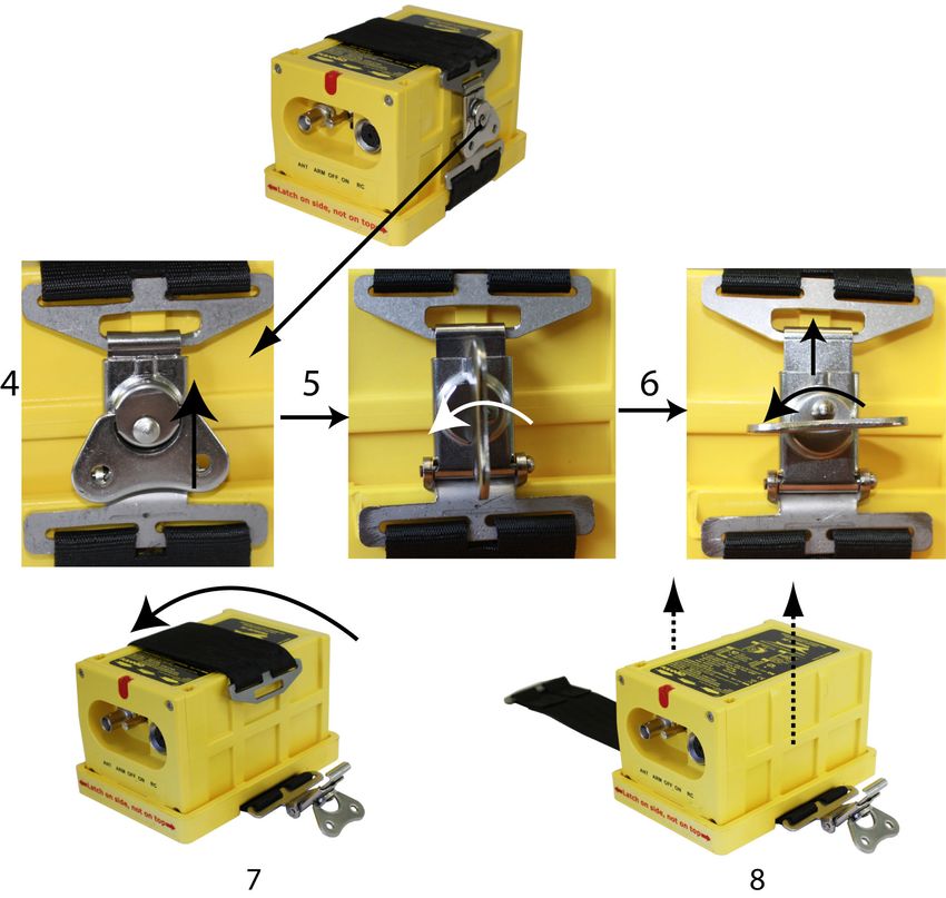
OPERATION MANUAL
                                                         AF INTEGRA / AF-H INTEGRA ELT

                              LIST OF EFFECTIVE PAGES

        SUBJECT                                                            PAGE   DATE
        Title Page
                                                                      TP     1    SEP 03/2021
        Record of Revisions
                                                                    ROR      1    SEP 03/2021
                                                                    ROR      2    SEP 03/2021
        List of Effective Pages
                                                                    LEP      1    SEP 03/2021
                                                                    LEP      2    SEP 03/2021
                                                                    LEP      3    SEP 03/2021
                                                                    LEP      4    SEP 03/2021
        Table of Contents
                                                                    TOC      1    SEP 03/2021
                                                                    TOC      2    SEP 03/2021
                                                                    TOC      3    SEP 03/2021
                                                                    TOC      4    SEP 03/2021
        Introduction
                                                                  INTRO      1    SEP 03/2021
                                                                  INTRO      2    SEP 03/2021
        System Overview
                                                                             1    SEP 03/2021
                                                                             2    SEP 03/2021
                                                                             3    SEP 03/2021
                                                                             4    SEP 03/2021
                                                                             5    SEP 03/2021
                                                                             6    SEP 03/2021
                                                                             7    SEP 03/2021

                                                                                         LEP PAGE: 1
© 2021 Orolia S.A.S. All rigths are strictly reserved.
                                                                                         SEP 03/2021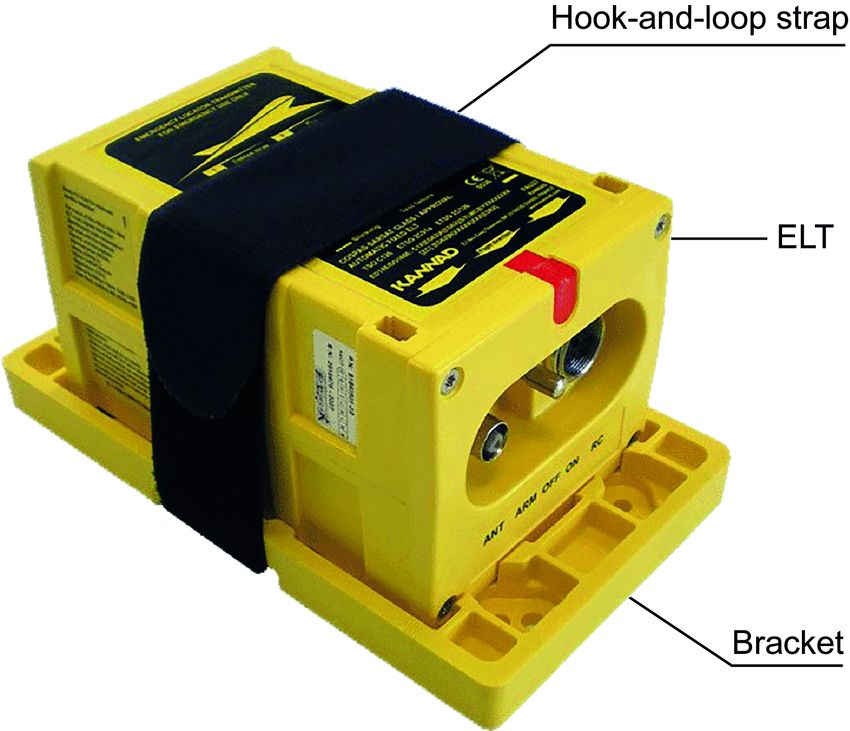
OPERATION MANUAL
                                                         AF INTEGRA / AF-H INTEGRA ELT

                              LIST OF EFFECTIVE PAGES

        SUBJECT                                                          PAGE    DATE
                                                                            8    SEP 03/2021
        System Functional Description and Operation
                                                                           101   SEP 03/2021
                                                                           102   SEP 03/2021
                                                                           103   SEP 03/2021
                                                                           104   SEP 03/2021
                                                                           105   SEP 03/2021
                                                                           106   SEP 03/2021
                                                                           107   SEP 03/2021
                                                                           108   SEP 03/2021
                                                                           109   SEP 03/2021
                                                                           110   SEP 03/2021
                                                                           111   SEP 03/2021
                                                                           112   SEP 03/2021
        Installation / Removal
                                                                           201   SEP 03/2021
                                                                           202   SEP 03/2021
                                                                           203   SEP 03/2021
                                                                           204   SEP 03/2021
                                                                           205   SEP 03/2021
                                                                           206   SEP 03/2021
                                                                           207   SEP 03/2021
                                                                           208   SEP 03/2021
                                                                           209   SEP 03/2021
                                                                           210   SEP 03/2021
                                                                           211   SEP 03/2021

                                                                                         LEP PAGE: 2
© 2021 Orolia S.A.S. All rigths are strictly reserved.
                                                                                         SEP 03/2021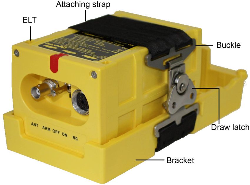
OPERATION MANUAL
                                                         AF INTEGRA / AF-H INTEGRA ELT

                              LIST OF EFFECTIVE PAGES

        SUBJECT                                                          PAGE    DATE
                                                                           212   SEP 03/2021
                                                                           213   SEP 03/2021
                                                                           214   SEP 03/2021
        Check
                                                                           301   SEP 03/2021
                                                                           302   SEP 03/2021
                                                                           303   SEP 03/2021
                                                                           304   SEP 03/2021
        Troubleshooting
                                                                           401   SEP 03/2021
                                                                           402   SEP 03/2021
        Schematics and Diagrams
                                                                           501   SEP 03/2021
                                                                           502   SEP 03/2021
                                                                           503   SEP 03/2021
                                                                           504   SEP 03/2021
                                                                           505   SEP 03/2021
                                                                           506   SEP 03/2021
        Servicing
                                                                           601   SEP 03/2021
                                                                           602   SEP 03/2021

                                                                                         LEP PAGE: 3
© 2021 Orolia S.A.S. All rigths are strictly reserved.
                                                                                         SEP 03/2021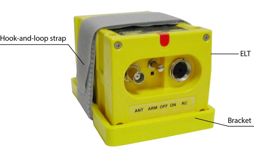
OPERATION MANUAL
                                                         AF INTEGRA / AF-H INTEGRA ELT

                              LIST OF EFFECTIVE PAGES

                                PAGE INTENTIONALLY LEFT BLANK

                                                                                         LEP PAGE: 4
© 2021 Orolia S.A.S. All rigths are strictly reserved.
                                                                                         SEP 03/2021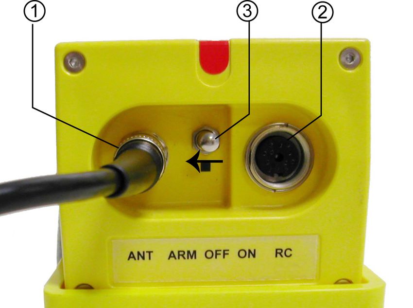
OPERATION MANUAL
                                                            AF INTEGRA / AF-H INTEGRA ELT

                                               TABLE OF CONTENTS

   INTRODUCTION...................................................................................... 1
   WARRANTY ............................................................................................ 2
    Scope ..................................................................................................... 2
    Exclusion................................................................................................ 2
   SYSTEM OVERVIEW .............................................................................. 1
    Cospas-Sarsat System .......................................................................... 1
        Description.............................................................................................................. 1
        Worldwide coverage with the Cospas-Sarsat system............................................. 2
        Operation ................................................................................................................ 2
        Environmental improvements of ELTs.................................................................... 2
      INTEGRA ELT System Presentation ..................................................... 3
      LINE REPLACEABLE UNITS ................................................................ 5
        Transmitter ............................................................................................................. 5
        Bracket ................................................................................................................... 5
         ELT with hook-and-loop Mounting Bracket .......................................................... 6
         ELT with draw latch Mounting Bracket................................................................. 7
        External antenna .................................................................................................... 8
   SYSTEM FUNCTIONAL DESCRIPTION AND OPERATION ............. 101
    Transmitter Functional Description .................................................... 101
        Transmission ...................................................................................................... 101
        Controls & Connectors ....................................................................................... 101
        Working mode information.................................................................................. 102
         Off .................................................................................................................... 102
         Self-Test........................................................................................................... 102
         Armed............................................................................................................... 103
         On .................................................................................................................... 103
        VSWR Switch function (External / Built-in back-up antenna) ............................. 104
        GPS Strategy...................................................................................................... 104
         Basic Installation (without NAV Interface equipment) ...................................... 104
         Installation including a NAV Interface equipment (Dongle IF GPS RS232) ..... 105
        Autonomy ........................................................................................................... 105
        Electrical interfaces ............................................................................................ 106
        Transmitter Technical Specifications .................................................................. 107
      Equipment limitations ......................................................................... 109
      Activation............................................................................................ 109
        Standby mode for automatic activation............................................................... 109
        Manual activation................................................................................................ 109
      Off ...................................................................................................... 110
      Self-Test............................................................................................. 110

                                                                                                                        TOC PAGE: 1
© 2021 Orolia S.A.S. All rigths are strictly reserved.
                                                                                                                         SEP 03/2021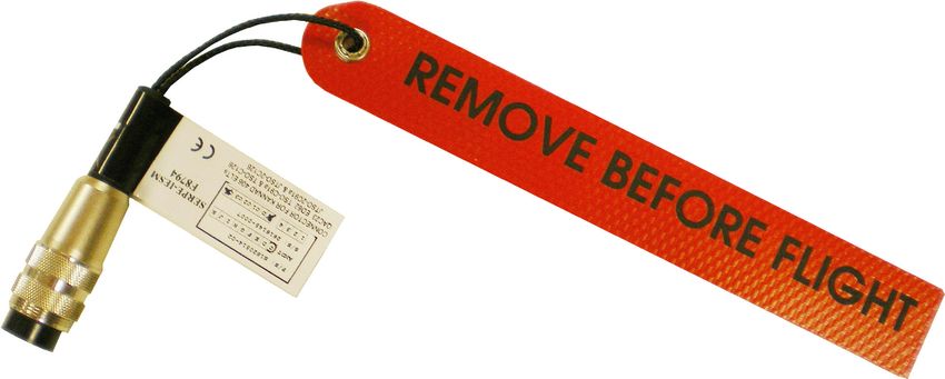
OPERATION MANUAL
                                                         AF INTEGRA / AF-H INTEGRA ELT

                                      TABLE OF CONTENTS

     Compatibility list ................................................................................. 111
       Mounting brackets .............................................................................................. 111
       Remote control panels (RCP) ............................................................................ 111
       DIN-12 connector or programming dongles ....................................................... 112
       Outside buzzer ................................................................................................... 112
       External antennas .............................................................................................. 112
   INSTALLATION / REMOVAL.............................................................. 201
    Registration........................................................................................ 201
       General............................................................................................................... 201
       Registration in USA ............................................................................................ 201
       Registration in Canada....................................................................................... 202
     Programming ..................................................................................... 203
       "Pin programming" option................................................................................... 203
     ELT installation procedure ................................................................. 204
         ELT Installation with hook-and-loop mounting brackets .................................. 204
         ELT installation with draw latch mounting bracket P/N S1850551-02 ............. 206
         ELT installation with draw latch mounting bracket P/N S1850551-04 ............. 208
     ELT Connection ................................................................................. 210
     First power up .................................................................................... 210
     ELT removal....................................................................................... 211
         Removal of the ELT from a hook-and-loop mounting bracket ......................... 211
         Removal of the ELT from a draw latch mounting bracket ................................ 212
   CHECK ................................................................................................ 301
    Self-test.............................................................................................. 301
       Periodicity........................................................................................................... 301
       Self-test procedure ............................................................................................. 301
     Operational tests................................................................................ 302
       ELT operational tests ......................................................................................... 302
       Test of transmitted signals ................................................................................. 302
        406 MHz Transmission tests............................................................................ 303
        121.5 MHz Transmission test .......................................................................... 304
   TROUBLESHOOTING......................................................................... 401
    General .............................................................................................. 401
    Faults on Self-test .............................................................................. 401
       Red visual indicator ............................................................................................ 401
        3+1 flashes ...................................................................................................... 401
        3+2 flashes ...................................................................................................... 401
        3+3 flashes ...................................................................................................... 401
        3+4 flashes ...................................................................................................... 401
        3+5 flashes ...................................................................................................... 401
        3+6 flashes ...................................................................................................... 401

                                                                                                                    TOC PAGE: 2
© 2021 Orolia S.A.S. All rigths are strictly reserved.
                                                                                                                     SEP 03/2021
OPERATION MANUAL
AF INTEGRA / AF-H INTEGRA ELT
TABLE OF CONTENTS
SCHEMATICS & DIAGRAMS ............................................................. 501
Outline dimensions and weight with Compact Mounting Bracket P/N
S1840502-01 ....................................................................................... 501
Outline dimensions and weight with Compact Universal Mounting
Bracket P/N S1840502-02 .................................................................. 502
Outline dimensions and weight with Bracket Universal for INTEGRA
ARINC e-NAV for ELT (AF) P/N S1850551-02 .................................... 503
Outline dimensions and weight with Mounting Bracket INTEGRA AF
P/N S1850551-04 ................................................................................ 504
AF INTEGRA ELTs , axis of installation............................................. 505
AF-H INTEGRA ELTs , axis of installation......................................... 505
SERVICING ......................................................................................... 601
Maintenance Schedule ...................................................................... 601
Periodic inspection ............................................................................................. 601
Battery replacement ........................................................................................... 601
Battery replacement requirements..................................................... 602
TOC PAGE: 3
© 2021 Orolia S.A.S. All rigths are strictly reserved.
SEP 03/2021OPERATION MANUAL
AF INTEGRA / AF-H INTEGRA ELT
TABLE OF CONTENTS
PAGE INTENTIONALLY LEFT BLANK
TOC PAGE: 4
© 2021 Orolia S.A.S. All rigths are strictly reserved.
SEP 03/2021OPERATION MANUAL
AF INTEGRA / AF-H INTEGRA ELT
INTRODUCTION
INTEGRA ELTs are an extension of the range of KANNAD ELTs. The
development of this type of ELTs is based on the improvement of safety of
flights either for light aircraft, business aircraft or commercial aviation.
The safety of flights is strengthened thanks to a built-in GPS giving a more
accurate position transmitted within minutes following the distress and a
built-in back-up Antenna which may replace the external antenna in case of
unavailability of the latter.
AF(1) INTEGRA is designed for fixed wing aircraft or helicopters, AF-H
INTEGRA is designed for flat installation on board helicopters only.
The AF INTEGRA (ER) and AF-H INTEGRA (ER) ELTs are evolutions of AF
INTEGRA and AF-H INTEGRA ELTs. The main evolution consists in the
extension to -40°C of temperature range.
The instructions in this manual provide the information necessary for the
installation and the operation of AF INTEGRA, AF-H INTEGRA, AF INTEGRA
(ER) and AF-H INTEGRA (ER) ELTs.
Servicing instructions of ELT are normally performed by shop personnel. For
detailed instructions, refer to Support section of Orolia Website.
For the initial installation, please refer to Initial Installation Manual supplied with
AF INTEGRA, AF-H INTEGRA, AF INTEGRA (ER) and AF-H INTEGRA (ER)
ELTs.
FOR REGULATORY REQUIREMENTS, PLEASE CONSULT YOUR
NATIONAL AVIATION AUTHORITY.
NOTE: (1) AF for Automatic Fixed
PAGE INTRO 1
© 2021 Orolia S.A.S. All rigths are strictly reserved.
SEP 03/2021OPERATION MANUAL
AF INTEGRA / AF-H INTEGRA ELT
WARRANTY
1. Scope
The equipment is warranted against all material or manufacturing defect for a
period of two years from the date of installation on the aircraft or thirty months
from the date of shipment from Orolia S.A.S. facilities whichever occur first.
Work carried out under the warranty shall not have the effect of extending the
warranty period.
In respect of this warranty, after a defect has been noted by our services, the
sole obligation incumbent upon us shall be the repair of the equipment or the
element identified as being defective by our services or possibly its
replacement free of charge, to the exclusion of all compensation or damages.
This warranty covers the cost of parts and labour in our factories.
The costs of transportation of the equipment replaced or repaired are the
purchaser's exclusive responsibility.
The risks shall be borne by the purchaser.
2. Exclusion
Defects and deterioration caused by natural wear of the product or by external
accident (poor maintenance, abnormal conditions of use, etc.) or by
modification of the equipment and tools not recommended nor specified by our
company, are excluded from the warranty.
Also the warranty shall not cover visible defects which the purchaser wouldn't
have formally notified Orolia S.A.S within 48 hours of receipt of the equipment.
© 2021 Orolia S.A.S. All rigths are strictly reserved.
PAGE INTRO 2
SEP 03/2021OPERATION MANUAL
AF INTEGRA / AF-H INTEGRA ELT
SYSTEM OVERVIEW
1. Cospas-Sarsat System
A. Description
Launched in the early eighties by the four founder countries (Canada, France,
Russia, USA), the Cospas-Sarsat system provides satellite aid to search and
rescue (SAR) operations for maritime, aeronautical and terrestrial vehicles
anywhere in the world.
It uses distress beacons fitted on mobiles and a constellation of LEO, MEO and
GEO satellites which relay and process the 406 MHz signal to ground stations
(LUT) where the beacon positions are determined.
Several types of beacons are designed to match the various applications of the
Cospas-Sarsat system:
• EPIRB (Emergency Position Indicating Radio Beacon) for maritime
applications.
• ELT (Emergency Locator Transmitter) for aeronautical applications.
• PLB (Personal Locator Beacon) for land expeditions.
Figure 1: Cospas-Sarsat System
PAGE: 1
© 2021 Orolia S.A.S. All rigths are strictly reserved.
SEP 03/2021OPERATION MANUAL
AF INTEGRA / AF-H INTEGRA ELT
B. Worldwide coverage with the Cospas-Sarsat system
The major improvement is the use of the Cospas-Sarsat system for processing
aeronautical emergencies.
The 406 MHz transmission carries digital data which enable the identification
of the aircraft in distress and facilitate SAR operation (type of the aircraft,
number of passengers, type of emergency).
The 406 MHz message is transmitted to the Cospas-Sarsat satellites. This
message is downloaded to one of the 64 ground stations (44 LEOLUTs and 20
GEOLUTs).
The aircraft is located by an independent location capability from the LEO and
MEO system.
Thanks to the built-in GPS receiver, the encoded position will be transmitted
in the distress message by the ELT within minutes following the distress.
The 121.5 MHz frequency is used by SAR services for homing in the final stage
of rescue operations.
C. Operation
In the event of a crash, the ELT activates automatically and transmits a sweep
tone on 121.5 MHz and the 406 MHz signal in space.
In a crash, a G-Switch (crash sensor) activates the ELT when the ELT is
subjected to an important change of velocity (or deceleration).
Activation may also be accomplished by manual means of a Remote Control
Panel (RCP) from the cockpit or directly from a switch of the ELT’s front panel.
In the event the external antenna is unavailable due to the crash
conditions, the built in back-up antenna will replace it to transmit the 406
MHz signal to the Cospas-Sarsat satellites.
D. Environmental improvements of ELTs
The certification of an ELT includes a range of severe mechanical tests:
• resistance to flame;
• impact and crush tests;
• resistance up to 500 G shocks;
• watertightness;
• anti-deflagration;
• extreme temperatures .
PAGE: 2
© 2021 Orolia S.A.S. All rigths are strictly reserved.
SEP 03/2021OPERATION MANUAL
AF INTEGRA / AF-H INTEGRA ELT
2. INTEGRA ELT System Presentation
AF INTEGRA and AF-H INTEGRA belong to the AF type of ELTs which are
permanently attached to an aircraft. AF INTEGRA and AF-INTEGRA (ER) are
designed to be installed on fixed wing aircraft or helicopters. AF-H INTEGRA
and AF-H INTEGRA (ER) are designed for flat installation on board helicopters
only.
The INTEGRA ELT system (Refer to Section Figure 2: ELT Standard System
Description page 4) is composed of:
1. the ELT transmitter:
• P/N S1851501-01 for AF INTEGRA (ER) or,
• P/N S1851501-02 for AF INTEGRA or,
• P/N S1852501-01 for AF-H INTEGRA (ER) or,
• P/N S1852501-02 for AF-H INTEGRA
2. a mounting bracket (P/N S1840502-01, S1840502-02, S1850551-02 or
S1850551-04);
3. an approved external whip, rod or blade antenna;
4. a remote control panel(see NOTE 1);
5. a DIN-12 connector, programming dongle or dongle IF GPS RS232(2)
when the optional RCP is connected.
6. an outside buzzer (optional).
NOTE: (1) The RCP is optional only if the commands and controls of
the ELT are reachable and visible from the pilot seated position.
(RTCA DO-204A):
"Equipment control and indicator installed for in-flight use shall be readily
accessible from the cockpit crew position. The cockpit crew shall have an
unobstructed view of visual indicator when in the normal seated position."
NOTE: (2) GPS/NAV Interface with an onboard RS232 GPS. Data position
from an onboard RS232 GPS is only available if a dongle IF GPS
RS232 is connected instead of programming dongle or DIN-12 con-
nector.
For details of approved part number of INTEGRA ELT system, Refer to Section
6. Compatibility list page 111.
The transmitter and bracket are installed in the aircraft near the tail. The
external antenna is mounted on the fuselage near the tail. The remote control
panel is installed in the cockpit and connected to the ELT with a DIN-12
connector or a programming dongle and a 2, 3, 4 or 5-wire bundle (not
supplied)
PAGE: 3
© 2021 Orolia S.A.S. All rigths are strictly reserved.
SEP 03/2021OPERATION MANUAL
AF INTEGRA / AF-H INTEGRA ELT
Figure 2: ELT Standard System Description
Figure 3: ELT System with Dongle IF GPS RS232 Description
PAGE: 4
© 2021 Orolia S.A.S. All rigths are strictly reserved.
SEP 03/2021OPERATION MANUAL
AF INTEGRA / AF-H INTEGRA ELT
3. LINE REPLACEABLE UNITS
A. Transmitter
The AF INTEGRA and AF-H INTEGRA are ELTs designed to be installed on
board aircraft to transmit a distress signal on frequencies:
• 406 MHz (Cospas-Sarsat frequency) for precise pinpointing and
identification of the aircraft in distress.
• 121.5 MHz used for homing in the final stages of the rescue operations.
The AF INTEGRA and AF-H INTEGRA are certified as Automatic Fixed (AF)
ELTs with the approved external antennas.
The housing of AF INTEGRA and AF-H INTEGRA transmitters are made of
molded plastic with excellent mechanical resistance.
The ELT housing is designed with no sharp edges.
Figure 4: ELT Transmitter
B. Bracket
The ELT must be installed into one of the approved mounting brackets. The
mounting bracket preferably installed near the tail is designed to secure the
ELT with a strap. This enables quick removal of the ELT for maintenance or
exchange.
Mounting brackets with hook-and-loop (Velcro®) strap are ETSO-2C126 /
TSO-C126a approved.
Mounting brackets with draw latch strap (non-hook-and-loop) are ETSO-126a
/ TSO-C126b approved.
PAGE: 5
© 2021 Orolia S.A.S. All rigths are strictly reserved.
SEP 03/2021OPERATION MANUAL
AF INTEGRA / AF-H INTEGRA ELT
Drilling holes of Universal Mounting Bracket are compatible with former
mounting brackets to re-use existing drilling for retrofit.
All mounting brackets are designed to allow the fastening mechanism to be
placed either to the left or to the right of the ELT.
IMPORTANT: Orolia S.A.S. recommends the use of TSO-C126b approved
mounting bracket.
Installation of INTEGRA and INTEGRA (ER) ELT with hook-and-loop
mounting brackets invalidates the TSO-C126b.
The summary of compatible mounting brackets is as follows:
P/N Designation Strap Approval
S1840502-01 COMPACT Mounting Bracket Hook-and-loop TSO-C126a
S1840502-02 COMPACT Universal Mounting Hook-and-loop TSO-C126a
Bracket
S1850551-04 Mounting Bracket INTEGRA AF Draw latch TSO-C126b
S1850551-02 Bracket Universal for INTEGRA Draw latch TSO-C126b
ARINC e-NAV for ELT (AF)
(Refer to DOC09081, Initial Installation Manual for the outline dimensions of
these brackets).
(1) ELT with hook-and-loop Mounting Bracket
Figure 5: INTEGRA ELT with Mounting Bracket P/N S1840502-01
PAGE: 6
© 2021 Orolia S.A.S. All rigths are strictly reserved.
SEP 03/2021OPERATION MANUAL
AF INTEGRA / AF-H INTEGRA ELT
Figure 6: INTEGRA ELT with Mounting Bracket P/N S1840502-02
(2) ELT with draw latch Mounting Bracket
Figure 7: INTEGRA ELT with Mounting Bracket P/N S1850551-04
PAGE: 7
© 2021 Orolia S.A.S. All rigths are strictly reserved.
SEP 03/2021OPERATION MANUAL
AF INTEGRA / AF-H INTEGRA ELT
Figure 8: INTEGRA ELT with Mounting Bracket P/N S1850551-02
C. External antenna
Only approved antennas may be installed (Refer to Section 6.
Compatibility list page 111).
Connection to the ELT will be carried out with a 50 Ohm coaxial cable (RG58
for example) ended with a male BNC connector.
IMPORTANT NOTICE:
Orolia S.A.S. recommends a cable with radio electric properties similar or
better to those of a RG58 cable.
NOTE: The 50 Ohm coaxial cable and the male BNC connector are not
supplied.
PAGE: 8
© 2021 Orolia S.A.S. All rigths are strictly reserved.
SEP 03/2021OPERATION MANUAL
AF INTEGRA / AF-H INTEGRA ELT
SYSTEM FUNCTIONAL DESCRIPTION AND OPERATION
1. Transmitter Functional Description
A. Transmission
The transmitter can be activated either automatically when the crash occurs
(thanks to a shock sensor) or manually (thanks to a switch on the transmitter
itself or on a RCP).
The transmitter is designed to transmit on two frequencies (121.5 and 406
MHz). The 121.5 Mhz is mainly used for homing in the final stages of the rescue
operations. The 406 MHz frequency is used by the Cospas-Sarsat satellites for
precise pinpointing and identification of the aircraft in distress.
Once activated, the transmitter operates continuously on 121.5 MHz.
During operations, a digital message is transmitted on 406.037 MHz every 50
seconds.
B. Controls & Connectors
The following controls are to be found on the ELT front panel (from left to right):
1. 3-position switch ARM/OFF/ON;
2. Red visual indicator;
3. DIN 12 socket for connection to an optional Remote Control Panel, a
programming dongle, dongle IF GPS RS232 or a programming
equipment;
4. BNC connector for the external antenna.
IMPORTANT: The switches are protected against inadvertent operation
by a locking latch. To operate the switches, the lever shall be pulled to
unlock then set to position.
Figure 101: Front Panel
PAGE: 101
© 2021 Orolia S.A.S. All rigths are strictly reserved.
SEP 03/2021OPERATION MANUAL
AF INTEGRA / AF-H INTEGRA ELT
The red visual indicator gives an indication on the working mode of the beacon:
• after the self test:
- a serie of short flashes, 200 ms, indicates a faulty functioning;
- one long flash, 1s, indicates a proper functioning;
• in operating mode:
- periodic flashes during 121.5 transmission;
- long flash during 406 transmission.
A buzzer gives audio information on the beacon working mode:
• continuous tone during self test;
• 1 beep every 0.7 second during 121.5 transmission;
• silence during 406 transmission.
C. Working mode information
CAUTION: WHEN OPERATING THE ARM/OFF/ON SWITCH, PULL LEVER
TO UNLOCK AND SET TO POSITION.
The ELT has 4 different modes:
• Off.
• Self-test (temporary mode).
• Armed (standby mode to enable automatic activation by the shock sensor
or by an optional remote control panel).
• On (transmission).
Transmission is effective if the beacon is activated (either manually on the ELT
control panel, automatically by the shock sensor, or remotely by the "ON"
switch of an optional remote control panel when connected).
(1)Off
The ELT is off when the switch is in the "OFF" position, no part of the ELT
is energized.
This mode must only be selected when the ELT is removed from the
aircraft or when the aircraft is parked for a long period or for maintenance.
(2) Self-Test
The self-test mode is a temporary mode (max duration 15 seconds) in
which the ELT checks the main characteristics of the transmitter (Battery
voltage, Programming...) and enables digital communication with
programming and test equipment.
This mode is selected:
• when switching from "OFF" to "ARM";
• when switching to "RESET / TEST" on an optional Remote Control
Panel (provided that the switch of the ELT is in the "ARM" position);
PAGE: 102
© 2021 Orolia S.A.S. All rigths are strictly reserved.
SEP 03/2021OPERATION MANUAL
AF INTEGRA / AF-H INTEGRA ELT
• when switching to "ON" prior to transmission.
The buzzer operates during the self-test procedure.
After about 10 seconds, the test result is displayed on the red visual
indicator as follows:
• One long flash, duration 1s, indicates a proper functioning.
• A series of short flashes, 200 ms, indicates a faulty functioning.
The number of flashes indicates the type of failure:
• 3 + 1 = LOW BATTERY VOLTAGE.
• 3 + 2 = LOW TRANSMISSION POWER.
• 3 + 3 = FAULTY VCO LOCKING (FAULTY FREQUENCY).
• 3 + 4 = NO IDENTIFICATION PROGRAMMED.
• 3 + 5 = FAULTY VSWR (LINK TO EXTERNAL ANTENNA).
• 3 + 6 = INTERNAL GPS SERIAL LINK.
It is recommended to test the ELT regularly in order to detect any possible
failure (Refer to Section A. Periodicity page 301).
The number of self-tests carried out is recorded. This information is
available when the ELT is connected to a programming equipment
(PR600).
(3) Armed
In order to enable activation by the G-Switch or with an optional Remote
Control Panel, the ELT must be in standby mode with the switch in the
"ARM" position.
This mode is mandatory during flight. The ELT should remain in the
"ARM" position except when the aircraft is parked for a long period or for
maintenance.
(4) On
This mode is selected:
• manually by switching the ELT to "ON";
• by switching an optional Remote Control Panel switch to "ON"
(provided that the ELT switch is in the "ARM" position);
• automatically when a crash occurs (provided that the ELT switch is in
the "ARM" position).
When this mode is selected, the ELT starts transmitting:
• after 50 seconds on 406 MHz (one 406 MHz burst every 50 seconds)
to the external antenna;
PAGE: 103
© 2021 Orolia S.A.S. All rigths are strictly reserved.
SEP 03/2021OPERATION MANUAL
AF INTEGRA / AF-H INTEGRA ELT
• after the GPS lock on 121.5 MHz (continous transmission between
each 406 MHz burst). If GPS lock does not occur within 5 minutes, the
121.5 MHz will be activated.
The red visual indicator on the ELT (and on an optional remote control
panel when connected) flashes and the buzzer operates.
• Red visual indicator:
- 1 short flash during ELT transmission on 121.5 MHz (every 0.7
seconds);
- 1 long flash during ELT transmission on 406 MHz (every 50
seconds).
• Buzzer:
- 1.5 Hz pulse signal (recurrence 0.7 s) during ELT transmission on
121.5 MHz [except if the ELT has switched to built-in back-up
antenna: Refer to D. VSWR Switch function (External / Built-in
back-up antenna)].
In case of accidental activation, the ELT can be reset either by switching it
to "OFF" or by switching to "RESET" on an optional Remote Control Panel
when connected.
The number of 406 MHz bursts transmitted is recorded. This information is
available when the ELT is connected to a programming and test
equipment (PR600).
D. VSWR Switch function (External / Built-in back-up antenna)
During the 406 MHz burst, the Voltage Standing Wave Ratio (VSWR) is
measured. After 5 bursts with wrong VSWR measurements, the ELT switches
from the external to the built-in back-up antenna in order to optimize transmitted
signal.
In On mode, after 36 bursts, the ELT decides to re-switch or not according to
the result of 2 new VSWR measurements.
NOTE: When shifting from the external to the built-in back-up antenna the pulse
signal of the buzzer shifts from one beep every 0.7 second to 2 beeps every 0.7
second.
E. GPS Strategy
(1)Basic Installation (without NAV Interface equipment)
To avoid consumption, the internal GPS receiver is not power supplied in
Armed mode. After a crash (automatic activation) or manual activation, the
internal GPS will try to acquire a position in continuous mode during one hour
and by different sequences up to 24 hours of 406 MHz transmission. If the
PAGE: 104
© 2021 Orolia S.A.S. All rigths are strictly reserved.
SEP 03/2021OPERATION MANUAL
AF INTEGRA / AF-H INTEGRA ELT
internal GPS receiver acquires a valid position, then the message will contain
the true position in the next 406 MHz burst. If the internal GPS receiver does
not acquire a valid position, then the message will contain the default value
(GPS position not valid).
(2) Installation including a NAV Interface equipment (Dongle IF GPS
RS232)
When valid, the position of the internal GPS will always take priority, even if
a Dongle IF GPS RS232 is connected to the GPS equipment of the aircraft
(external GPS):
• If only the external GPS acquires a valid position, then the message will
contain the true position of the external GPS in the 406 MHz burst;
• If both internal and external GPS acquire a valid position, then the
message will contain the true position of the internal GPS;
• If neither the internal GPS, nor the external GPS acquire a valid position,
then the message will contain the default value (GPS position not valid).
According to § 4.5.5.2 of Cospas Sarsat C/S T001, if, after providing valid data,
the navigation input fails or is not available, the beacon message retains the
last valid position for 4 hours (± 5 min) after the last valid position data input.
After 4 hours the encoded position is set to the default values.
F. Autonomy
The energy is provided by a battery pack composed of a LiMnO2 two-element
battery (See pages page 107 & page 602 for Kit battery reference).
Lithium cells, lithium batteries and equipment containing such
batteries are subjected to regulations and classified under class 9 as
from 1st of January 2003.
Battery
Type: LiMnO2 two-element battery
Battery Expiry Date: 7 years from date of cell manufacturing (CDOM)
Battery Replacement: according to expiry date written on the battery pack and
on the ELT label.
IMPORTANT: If the ELT has been activated for more than 1 hour, the
battery shall be replaced (See Refer to Section 2. Battery replacement
requirements page 602)
Until the battery expiry date, the duration of the 121.5 transmission is over 48
hours at -20°C for INTEGRA ELTs and over 48 hours at -40°C for INTEGRA
(ER) ELTs.
As it is therefore preferable to keep the battery power for 121.5 MHz homing
PAGE: 105
© 2021 Orolia S.A.S. All rigths are strictly reserved.
SEP 03/2021OPERATION MANUAL
AF INTEGRA / AF-H INTEGRA ELT
frequency transmission for the rescue operations, in compliance with Cospas-
Sarsat specifications, the 406 MHz transmission is deliberately stopped after
24 hours to extend the 121.5 MHz transmission for as long as possible.
G. Electrical interfaces
J1
DIN 12 socket J1 is dedicated for connection to an optional Remote Control
Panel, to a Programming or Maintenance Dongle or to a programming
equipment (PR600).
IMPORTANT:
Shielded cables are recommended. The required wires are AWG24.
J1 PIN Signal Name Destination Direction
J1-A RCP RESET RCP IN
J1-B DONGLE RX SMM / PGM IN
Viewed from J1-C DONGLE CS SMM OUT
Front Face J1-D DONGLE SK SMM OUT
J1-E DONGLE TX SMM / PGM OUT
J1-F DONGLE ALE2P SMM OUT
J1-G RCP COMMON RCP OUT
J1-H RCP BUZZER RCP OUT
J1-J RCP LED RCP OUT
J1-K RCP ON RCP OUT
J1-L DONGLE GND SMM / PGM OUT
J1-M RCP 2W COMMON RCP OUT
Table 1: J1 connector pin-out
J2
BNC female connector J2 is used to connect the external antenna through a
50 coaxial cable.
IMPORTANT NOTICE:
The use of a low attenuation coaxial cable is recommended. The
maximum permitted attenuation in the coaxial cable is 2 dB@406 MHz.
PAGE: 106
© 2021 Orolia S.A.S. All rigths are strictly reserved.
SEP 03/2021OPERATION MANUAL
AF INTEGRA / AF-H INTEGRA ELT
H. Transmitter Technical Specifications
TYPE CONTROLS
• Two-frequency ELT • ARM / OFF / ON switch
(121.5 / 406.037 MHz) • DIN12 socket for RCP and pin
• Automatic Fixed programming option
• Cospas-Sarsat Class • Bright red visual indicator
INTEGRA AF (ER)/AF-H (ER): • Buzzer
Class I, -40°C to +55°C • BNC antenna connector
INTEGRA AF/AF-H: BATTERY
Class II, -20°C to +55°C KIT BAT200, P/N: S1840510-01
406 MHz TRANSMISSION LiMnO2 two-element battery for transmitter
• Frequency: 406.037 MHz ±1 kHz power supply
• Output power: 5W (37 dBm ±2 dB) Battery expiry date: 7 years from date of cell
• Modulation type: 16K0G1D (Biphase L manufacturing
encoding) HOUSING
• Transmission duration: Material: Polycarbonate
520ms (long message) every 50 s. Color: Yellow (color compounded)
• Autonomy Transmitter dimensions:
INTEGRA (ER): 24 Hours @-40°C 131 x 86 x 75.4 mm
INTEGRA: 24 Hours @-20°C ( 5.157 x 3.385 x 2.968 inches)
121.5 MHz TRANSMISSION Weight:
• Frequency: • AF: typical 755 g. (1.66 lb).
121.5 MHz ±6 kHz • AF-H: typical 760 g. (1.67 lb).
• Output power: 50 to 400 mW (17dBm Tightness: O-ring
to 26 dBm), typical 100 mW ENVIRONMENTAL CONDITIONS
• Modulation type: 3K20A3X RTCA DO-160F / EUROCAE ED14F
• Modulation rate: > 85 % Section 4 to 26:
• Frequency of modulation signal: INTEGRA AF / AF (ER)
1600 Hz to 300 Hz with decreasing [ED62A]X[ED62A]A[ED62A][R(C&C1)]XWX
sweep XXSZXXXZ[ED62A]B[XXG33]XXA
• Autonomy [ED62A]
INTEGRA (ER): INTEGRA AF-H / AF-H (ER)
over 48 hours@-40°C [ED62A]X[ED62A]A[ED62A][U(G)]XWXXXS
INTEGRA: ZXXXZ[ED62A]B[XXG33]XXA
over 48 hours@-20°C [ED62A]
G-SWITCH SENSOR QUALIFICATIONS
Mechanical G-switch sensor compliant with ETSO-C126a / TSO-C126a / TSO-C126b
EUROCAE ED62 specifications NOTE: Installation of INTEGRA and
RF Field strenght limits INTEGRA (ER) ELT with brackets
INTEGRA (ER): 0.471 V/m P/N S1840502-01 and S1840502-02
INTEGRA: 0.474 V/m invalidates the TSO-C126b.
Hardware - DAL E FOR USE OUTSIDE OF THE USA OR
• AF (ER) P/N S1850611-01 EASA RULES, CONTACT YOUR LOCAL
• AF P/N S1850611-02 CIVIL AVIATION AUTHORITY.
• AF-H (ER) P/N S1850621-01
• AF-H P/N S1850621-02
Software - DAL D
• P/N YLS1816
PAGE: 107
© 2021 Orolia S.A.S. All rigths are strictly reserved.
SEP 03/2021OPERATION MANUAL
AF INTEGRA / AF-H INTEGRA ELT
Table 2: ENVIRONMENTAL QUALIFICATION FORM
Conditions Section Description of tests conducted
Temperature and Altitude 4.0 As per ED-62A
Low Temperature 4.5.1 As per ED-62A -40°C
High Temperature 4.5.2 & 4.5.3 As per ED-62A +55°C
In-Flight Loss Cooling 4.5.4 Cat. X, no test performed
Altitude 4.6.1 As per ED-62A 50,000 ft
Decompression 4.6.2 As per ED-62A
Overpressure 4.6.3 As per ED-62A
Temperature Variation 5.0 As per ED-62A
Humidity 6.0 Cat. A
Operational Shock and Crash Safety 7.0 As per ED-62A
AF type Cat. R(C,C1)
Vibration 8.0
AF-H Type Cat. U(G)
Explosive Atmosphere 9.0 Cat. X, no test performed
Waterproofness 10.0 Cat. W
Fluids Susceptibility 11.0 Cat. X, no test performed
Sand and Dust 12.0 Cat. X, no test performed
Fungus 13.0 Cat. X, no test performed
Salt Fog 14.0 Cat. S
Magnetic Effect 15.0 Cat. Z
Power Input 16.0 Cat. X, no test performed
Voltage Spike 17.0 Cat. X, no test performed
Audio Frequency Susceptibility 18.0 Cat. X, no test performed
Induced SignalSusceptibility 19.0 Cat. Z
Radio Frequency Susceptibility 20.0 As per ED-62A
Radio Frequency Emission 21.0 Cat. B
Lightning Induced Transient Susceptibility 22.0 XXG33
Lightning Direct Effects 23.0 Cat. X, no test performed
Icing 24.0 Cat. X, no test performed
Electrostatic Discharge 25.0 Cat. Z
Fire, Flammabilty 26.0 As per ED-62A
PAGE: 108
© 2021 Orolia S.A.S. All rigths are strictly reserved.
SEP 03/2021OPERATION MANUAL
AF INTEGRA / AF-H INTEGRA ELT
2. Equipment limitations
Antenna - ELT cable with maximum permitted attenuation: 2 dB@406 MHz.
WARNING:
ELTS ARE RADIO TRANSMITTERS WHICH EMIT RADIO FREQUENCY
RADIATION WHEN ACTIVATED. WHEN TRANSMITTING, THE USER'S
MINIMUM DISTANCE OF EXPOSURE IS 0.20 METER.
For RF Field strenght limits, please Refer to Section H. Transmitter
Technical Specifications page 107. RF Field strenght limits have been
calculated according to Canadian RSS-102 Standard "Radio Frequency
(RF) Exposure Compliance of Radiocommunication Apparatus (All
Frequency Bands)".
For Canadian user, any information and/or contact on Radiofrequency (RF)
Energy and Health may be found on:
http://www.ic.gc.ca/eic/site/smt-gst.nsf/eng/sf08792.html.
3. Activation
CAUTION: WHEN OPERATING THE ARM/OFF/ON SWITCH, PULL LEVER
TO UNLOCK AND SET TO POSITION.
A. Standby mode for automatic activation
In order to be automatically activated by the crash sensor, the ELT must be in
standby mode. This mode is mandatory during the flight. We recommend to
switch off the ELT only when removed from the aircraft or when the aircraft is
parked for a long period or for a maintenance operation.
• Check that the antenna is correctly connected.
• Switch to "ARM".
To operate the ELT with an optional Remote Control Panel, ensure that:
• The ELT switch is in the "ARM" position .
B. Manual activation
• Check that the antenna is correctly connected.
• Switch to "ON" (either on the ELT or on an optional Remote Control Panel
when connected):
- The ELT starts with the self-test sequence then, after 50 seconds,
transmits on:
• 406 MHz (one 406 MHz burst every 50 seconds);
• 121.5 MHz (continous transmission between each 406 MHz burst
after the GPS lock) .
PAGE: 109
© 2021 Orolia S.A.S. All rigths are strictly reserved.
SEP 03/2021OPERATION MANUAL
AF INTEGRA / AF-H INTEGRA ELT
- During transmission, the buzzer operates and the red visual indicator
flashes.
4. Off
CAUTION: WHEN OPERATING THE ARM/OFF/ON SWITCH, PULL LEVER
TO UNLOCK AND SET TO POSITION.
It is possible to stop the ELT in case of unintentional activation:
• Switch to "OFF".
Regulations state that no transmission must be interrupted unless
every means are used to contact and inform the Air Traffic Controller
of this action.
IMPORTANT NOTICE:
As 406 MHz transmission is effective 50 seconds after the ELT activation,
if it is switched off within this delay, no further radio contact will be
necessary.
5. Self-Test
Refer to Section 1. Self-test page 301
PAGE: 110
© 2021 Orolia S.A.S. All rigths are strictly reserved.
SEP 03/2021OPERATION MANUAL
AF INTEGRA / AF-H INTEGRA ELT
6. Compatibility list
A. Mounting brackets
Designation Part Number
COMPACT MOUNTING BRACKET KIT S1840502-01
COMPACT UNIVERSAL MOUNTING BRACKET KIT S1840502-02
BRACKET UNIVERSAL for INTEGRA ARINC e-NAV S1850551-02
for ELT (AF)
MOUNTING BRACKET INTEGRA AF S1850551-04
IMPORTANT:
Installation of INTEGRA and INTEGRA (ER) ELT with brackets P/N
S1840502-01 and S1840502-02 invalidates the TSO-C126b.
Orolia S.A.S. recommends the use of TSO-C126b approved mounting
brackets.
B. Remote control panels (RCP)
Designation Part Number
RC100 KIT S1820513-03
RC102 KIT S1820513-21
RC200 S1820513-11
RC300 S1820513-09
RC300-NVG S1820513-10
RC310-NVG S1820513-26
RC600 NVG (Y)(See Important Notice below) S1820513-12
RC600-NVG (W)(See Important Notice below) S1820513-13
RC800 S1820513-15
RC810 S1820513-23
IMPORTANT NOTICE:
RC600 RCP: Non ETSO equipment only designed to be installed on
military aircraft
PAGE: 111
© 2021 Orolia S.A.S. All rigths are strictly reserved.
SEP 03/2021OPERATION MANUAL
AF INTEGRA / AF-H INTEGRA ELT
C. DIN-12 connector or programming dongles
Designation Part Number
DIN-12 connector S1820514-03
Programming dongle S1820514-01
Programming dongle Assy S1820514-06
Programming dongle INTEGRA / LR S1820514-07
Dongle IF GPS RS232 S1820514-08(1)
Programming dongle INTEGRA / SA S1820514-11
NOTE (1): Fulfills functions of ELT to RCP cable, programming dongle and
GPS/NAV equipment interface when connected to an onboard RS232 GPS.
D. Outside buzzer
Designation Part Number
OUTSIDE BUZZER KIT S1820515-06
E. External antennas
Orolia Designation Manufacturer Orolia Part Number
N/A CHELTON 21-41 N/A
WHIP ANTENNA AV100 RAMI AV-100 0147444
WHIP ANTENNA AV200 RAMI AV-200 0146150
ROD ANTENNA AV300 RAMI AV-300 0146151
ROD ANTENNA ANT300 CHELTON 1327-82 0124220
BLADE ANTENNA ANT500 SENSOR SYSTEMS 0124222
S65-8282-406
BLADE ANTENNA ANT560 DAYTON GRANGER 0145787
ELT10-696-1
BLADE ANTENNA ANT650 CHELTON 2624-82 0124251
BLADE ANTENNA ANT700 CHELTON 2632-82 1002063
PAGE: 112
© 2021 Orolia S.A.S. All rigths are strictly reserved.
SEP 03/2021OPERATION MANUAL
AF INTEGRA / AF-H INTEGRA ELT
INSTALLATION / REMOVAL
CAUTION: WHEN OPERATING THE ARM/OFF/ON SWITCH, PULL LEVER
TO UNLOCK AND SET TO POSITION.
1. Registration
A. General
The ELT must be registered prior to installation on board.
When a 406 MHz ELT is installed in an aircraft, it is imperative the aircraft
owner register the ELT. Each 406 MHz ELT contains a unique identification
code that is transmitted to the satellite. This helps the “Rescue Coordination
Center” (RCC) to determine whether an emergency has actually occurred. The
unique identification permits accessing a data base.
The registration card available from the local registration authority must be
completed and returned to this authority.
Any change of ownership shall also be declared and registered with the local
registration authority.
B. Registration in USA
Mail or Fax your registration form to:
SARSAT BEACON REGISTRATION
NOAA
NSOF, E/SPO53
1315 East West Hwy
Silver Spring, MD 20910
or Save Time! Register your beacon online at:
www.beaconregistration.noaa.gov
All online registrations will be entered into the National 406 MHz Beacon
Registration Database on the same day of entry. Registration forms received
via postal mail will be entered within 2 business days of receipt. For online
registrations, a confirmation letter with your completed registration information
form will be sent immediately via e-mail or fax (if provided). Confirmation letters
sent via postal mail should arrive within two weeks. Once your registration
confirmation is received, please review all information. Any changes or updates
to your registration information can be done via the internet, fax, e-mail or
postal mail. If you do not receive your registration confirmation from NOAA on
the same day you submit it over the internet or within two weeks if you submit
it by postal mail, please call NOAA toll-free at: 1-888-212-SAVE (7283) or
301-817-4515 for assistance.
PAGE: 201
© 2021 Orolia S.A.S. All rigths are strictly reserved.
SEP 03/2021OPERATION MANUAL
AF INTEGRA / AF-H INTEGRA ELT
After initial registration (or re-registration) you will receive a NOAA Proof of
Registration Decal by postal mail. This decal is to be affixed to the beacon and
should be placed in such a way that it is clearly visible. If for some reason you
do not receive the registration decal within two weeks, please call NOAA toll-
free at: 1-888-212-SAVE (7283) or 301-817-4515.
Failure to register, re-register (as required every two years), or to notify NOAA
of any changes to the status of your 406 MHz beacon could result in penalties
and/or fines being issued under Federal Law. The owner or user of the beacon
is required to notify NOAA of any changes to the registration information at any
time. By submitting this registration the owner, operator, or legally authorized
agent declares under penalty of law that all information in the registration
information is true, accurate, and complete. Providing information that is
knowingly false or inaccurate may be punishable under Federal Statutes.
Solicitation of this information is authorized by Title 47 - Parts 80, 87, and 95 of
the U.S. Code of Federal Regulations (CFR). Additional registration forms can
be found on the NOAA-SARSAT website at:
www.sarsat.noaa.gov or at: www.beaconregistration.noaa.gov
C. Registration in Canada
Beacon information is held in the Canadian Beacon Registry maintained by the
National Search and Rescue Secretariat for use in search and rescue
operations. Online access to the Registry is available for all beacon owners to
register new beacons or to update their beacon information. You can add or
update your beacon information by accessing the registry directly, sending in a
completed registration form or by talking to one of our beacon registry
representatives.
You can access the registry:
• online: www.canadianbeaconregistry.com
• by email: CBR@Sarnet.dnd.ca
• by fax: 1-613-996-3746
• by telephone: 1-800-727-9414 or 1-613-996-1616
The registration information must be updated when the aircraft ownership
changes as per the Canadian Airworthiness Notice AN B029 (refer to following
link):
http://www.nss.gc.ca/site/Emergency_Beacons/canadian_beacon_registry_e.asp
Additional information and registration forms can be found on the Canadian
NSS website at:
http://www.nss.gc.ca/site/cospas-sarsat/INTRO_e.asp
PAGE: 202
© 2021 Orolia S.A.S. All rigths are strictly reserved.
SEP 03/2021OPERATION MANUAL
AF INTEGRA / AF-H INTEGRA ELT
2. Programming
A. "Pin programming" option
The INTEGRA family offers pin-programming capabilities to facilitate
maintenance operations especially in the case of removals and/or
replacement.
A special DIN 12 connector with a Serial Memory Module (called "Programming
Dongle") is connected to the ELT when installed on board. This Programming
Dongle contains the identification information of the aircraft and remains on
board the aircraft. When an unprogrammed ELT is installed and connected to
this Programming Dongle and the "ELT" is switched to "ARM", it automatically
updates its own memory with the identification data contained in the
Programming Dongle memory.
When the ELT is removed from the aircraft, it keeps its identification data.
For maintenance purposes, it is possible to delete the identification information
of the ELT by connecting a "Maintenance Dongle" to the ELT. Any accidental
transmission with this "maintenance dongle" will not involve SAR operation as
the identification code transmitted is recognised by Cospas-Sarsat as "not on
board".
When a maintenance dongle is connected:
• Country code is 227 (France).
• Protocol is Test.
• Identification number is K + 6 digits (the 6 digits of the CSN number).
If the pin programming option is selected by the owner, the following equipment
are required:
• a "Programming Dongle" on each aircraft;
• a "Maintenance Dongle" on each ELT spare.
Figure 201: Maintenance Dongle
PAGE: 203
© 2021 Orolia S.A.S. All rigths are strictly reserved.
SEP 03/2021OPERATION MANUAL
AF INTEGRA / AF-H INTEGRA ELT
3. ELT installation procedure
(1)ELT Installation with hook-and-loop mounting brackets
Refer to Figure 202: ELT installation with a hook-and-loop mounting bracket
page 205
NOTE: Initial installation (bracket installation and first wiring) is described in
Initial installation manual, DOC09081 also supplied with the transmitter.
1. Mount the transmitter on the bracket
• For AF INTEGRA or AF INTEGRA (ER), with "Flight direction" arrow
of the ELT pointed towards the front of the aircraft according to
Section 4. Outline dimensions and weight with Mounting Bracket
INTEGRA AF P/N S1850551-04 page 504.
• For AF-H INTEGRA or AF-H INTEGRA (ER), with "Flight direction"
arrow of the ELT pointed towards the front or downwards the
helicopter according to Section 5. AF INTEGRA ELTs , axis of
installation page 505.
2. Slide the strap through the buckle. Ensure the buckle is correctly
positioned (indifferently on right or left side of ELT) regarding the
horizontal center line of ELT as shown Detail A.
3. Fasten the strap tightly.
IMPORTANT: Once installed in the mounting bracket, the installer
must be sure that the transmitter is firmly attached in its bracket by
trying to extract it manually, thereby verifying there is no play and
that it remains attached when extraction from the bracket is
attempted.
CAUTION:
AN INCORRECT TIGHTENING OF THE HOOK AND LOOP
FASTENER COULD LEAD TO AN UNSAFE SITUATION BY THE ELT
PREVENTING THE TRANSMISSION OF THE DISTRESS MESSAGE
PAGE: 204
© 2021 Orolia S.A.S. All rigths are strictly reserved.
SEP 03/2021OPERATION MANUAL
AF INTEGRA / AF-H INTEGRA ELT
Figure 202: ELT installation with a hook-and-loop mounting bracket
PAGE: 205
© 2021 Orolia S.A.S. All rigths are strictly reserved.
SEP 03/2021OPERATION MANUAL
AF INTEGRA / AF-H INTEGRA ELT
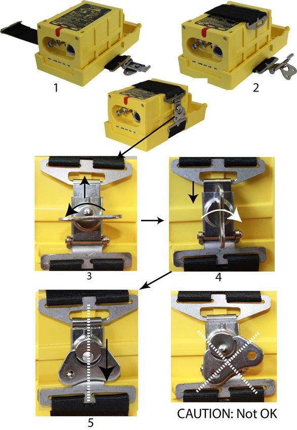
(2) ELT installation with draw latch mounting bracket P/N S1850551-02
Refer to: Figure 203: ELT installation with Bracket Universal for INTEGRA
ARINC e-NAV P/N S1850551-02
1. Place the INTEGRA ELT onto the Bracket with "Flight Direction Arrow"
of the ELT pointed towards the front of the aircraft.
2. Pass the strap with the buckle above the ELT.
3. Do a quarter turn counterclockwise to the latch then bring the hook of
the latch onto the buckle of the attaching strap.
4. Do a quarter turn clockwise to the latch to fix the attaching strap by
sliding the hook down.
5. Pull down the latch to lock the attaching strap.
CAUTION:
WHEN LOCKED, THE CENTER OF THE LATCH SHALL BE
ALIGNED WITH THE CENTER OF THE BUCKLE (Refer to: Figure
203: ELT installation with Bracket Universal for INTEGRA ARINC e-
NAV P/N S1850551-02, picture 5).
6. Check that the ELT is firmly attached:
IMPORTANT:
Once installed in the mounting bracket, the installer must be sure
that the transmitter is firmly attached in its bracket by trying to
extract it manually, thereby verifying there is no play and that it
remains attached when extraction from the bracket is attempted.
CAUTION:
AN INCORRECT LOCKING OF THE LATCH COULD LEAD TO AN
UNSAFE SITUATION BY THE ELT PREVENTING THE
TRANSMISSION OF THE DISTRESS MESSAGE.
PAGE: 206
© 2021 Orolia S.A.S. All rigths are strictly reserved.
SEP 03/2021OPERATION MANUAL
AF INTEGRA / AF-H INTEGRA ELT
Figure 203: ELT installation with Bracket Universal for INTEGRA ARINC e-NAV
P/N S1850551-02
PAGE: 207
© 2021 Orolia S.A.S. All rigths are strictly reserved.
SEP 03/2021OPERATION MANUAL
AF INTEGRA / AF-H INTEGRA ELT
(3) ELT installation with draw latch mounting bracket P/N S1850551-04
Refer to: Figure 204: ELT installation with Mounting Bracket INTEGRA AF P/N
S1850551-04
1. Place the INTEGRA ELT onto the Bracket with "Flight Direction Arrow"
of the ELT pointed towards the front of the aircraft.
2. Pass the strap with the buckle above the ELT.
3. Do a quarter turn counterclockwise to the latch then bring the hook of
the latch onto the buckle of the attaching strap.
4. Do a quarter turn clockwise to the latch to fix the attaching strap by
sliding the hook down.
5. Pull down the latch to lock the attaching strap.
CAUTION:
WHEN LOCKED, THE CENTER OF THE LATCH SHALL BE
ALIGNED WITH THE CENTER OF THE BUCKLE (Refer to Figure
204: ELT installation with Mounting Bracket INTEGRA AF P/N
S1850551-04 page 209, picture 5).
CAUTION:
NEVER INSTALL THE ATTACHING STRAP WITH THE LATCH OR
GROMMET ON TOP OF THE ELT, THIS WOULD PREVENT THE
RADIATION OF THE BUILT-IN BACK-UP ANTENNA AND
RECEPTION OF GPS SIGNAL.THE LATCH SHALL ALWAYS BE ON
SIDE OF THE ELT.
6. Check that the ELT is firmly attached:
IMPORTANT:
Once installed in the mounting bracket, the installer must be sure
that the transmitter is firmly attached in its bracket by trying to
extract it manually, thereby verifying there is no play and that it
remains attached when extraction from the bracket is attempted.
CAUTION:
AN INCORRECT LOCKING OF THE LATCH COULD LEAD TO AN
UNSAFE SITUATION BY THE ELT PREVENTING THE
TRANSMISSION OF THE DISTRESS MESSAGE.
PAGE: 208
© 2021 Orolia S.A.S. All rigths are strictly reserved.
SEP 03/2021You can also read