PXR 20/25 Trip Unit for Series NRX User Manual Power Xpert Release Trip Units - Instruction Manual MN013003EN
←
→
Page content transcription
If your browser does not render page correctly, please read the page content below
Instruction Manual MN013003EN

PXR 20/25 Trip Unit for Series NRX User Manual
Power Xpert® Release Trip Units
Instructions apply to:

         Series NRX, Type NF Frame,      Series NRX, Type RF Frame,
         UL489 / IEC, IZMX16             UL489 / IEC, IZMX40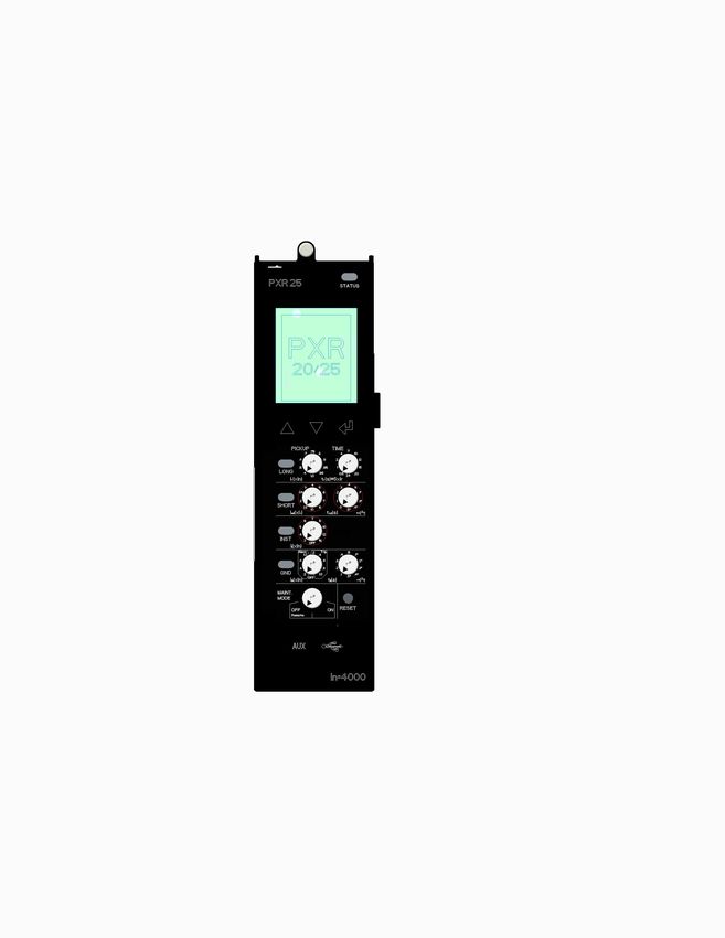
Instruction Manual MN013003EN

Contents

1. INTRODUCTION. . . . . . . . . . . . . . . . . . . . . . . . . . . . . . . . . . . . . . . . . . . . . . . . . . 1
         1.1 Introduction to the PXR 20/25 . . . . . . . . . . . . . . . . . . . . . . . . . . . . . . . . . . . . . . . . 1

2. PROTECTION AND METERING FEATURES . . . . . . . . . . . . . . . . . . . . . . . . . . . . 3
         2.1 Trip Unit Functions. . . . . . . . . . . . . . . . . . . . . . . . . . . . . . . . . . . . . . . . . . . . . . . . . 3
         2.2 Protection Features. . . . . . . . . . . . . . . . . . . . . . . . . . . . . . . . . . . . . . . . . . . . . . . . 4
         2.3 Current and Voltage Metering Data. . . . . . . . . . . . . . . . . . . . . . . . . . . . . . . . . . . . 5
         2.4 Power and Energy Metering Data. . . . . . . . . . . . . . . . . . . . . . . . . . . . . . . . . . . . . 6
         2.5 Time Current Curves . . . . . . . . . . . . . . . . . . . . . . . . . . . . . . . . . . . . . . . . . . . . . . . 6

3. POWER XPERT® RELEASE TRIP UNITS . . . . . . . . . . . . . . . . . . . . . . . . . . . . . . . 7
         3.1     Status Indicator . . . . . . . . . . . . . . . . . . . . . . . . . . . . . . . . . . . . . . . . . . . . . . . . . . 7
         3.2     Display and Navigation Buttons. . . . . . . . . . . . . . . . . . . . . . . . . . . . . . . . . . . . . . 7
         3.3     Pickup/Cause-of-Trip Indicators . . . . . . . . . . . . . . . . . . . . . . . . . . . . . . . . . . . . . . 8
         3.4     Rotary Switches. . . . . . . . . . . . . . . . . . . . . . . . . . . . . . . . . . . . . . . . . . . . . . . . . . 8
         3.5     Maintenance Mode Switch . . . . . . . . . . . . . . . . . . . . . . . . . . . . . . . . . . . . . . . . . 8
         3.6     Reset . . . . . . . . . . . . . . . . . . . . . . . . . . . . . . . . . . . . . . . . . . . . . . . . . . . . . . . . . . 8
         3.7     Tamper-Resistant Cover. . . . . . . . . . . . . . . . . . . . . . . . . . . . . . . . . . . . . . . . . . . . 8
         3.8     Door. . . . . . . . . . . . . . . . . . . . . . . . . . . . . . . . . . . . . . . . . . . . . . . . . . . . . . . . . . . 8
         3.9     USB . . . . . . . . . . . . . . . . . . . . . . . . . . . . . . . . . . . . . . . . . . . . . . . . . . . . . . . . . . . 9
         3.10 Temporary Auxiliary Power. . . . . . . . . . . . . . . . . . . . . . . . . . . . . . . . . . . . . . . . . . 9
         3.11 Battery. . . . . . . . . . . . . . . . . . . . . . . . . . . . . . . . . . . . . . . . . . . . . . . . . . . . . . . . . 9
         3.12 In Rating . . . . . . . . . . . . . . . . . . . . . . . . . . . . . . . . . . . . . . . . . . . . . . . . . . . . . . . . 9
         3.13 Side Labels. . . . . . . . . . . . . . . . . . . . . . . . . . . . . . . . . . . . . . . . . . . . . . . . . . . . . . 9

4. PXR PROTECTION SETTINGS. . . . . . . . . . . . . . . . . . . . . . . . . . . . . . . . . . . . . . 10
         4.1     Long Delay Pickup and Time Setting. . . . . . . . . . . . . . . . . . . . . . . . . . . . . . . . . 10
         4.2     Short Delay Pickup and Time Settings. . . . . . . . . . . . . . . . . . . . . . . . . . . . . . . . 10
         4.3     Instantaneous Pickup Setting . . . . . . . . . . . . . . . . . . . . . . . . . . . . . . . . . . . . . . 10
         4.4     Ground Fault Settings . . . . . . . . . . . . . . . . . . . . . . . . . . . . . . . . . . . . . . . . . . . . 10
         4.5     Ground Fault Sensing . . . . . . . . . . . . . . . . . . . . . . . . . . . . . . . . . . . . . . . . . . . .  11
         4.6     Maintenance Mode. . . . . . . . . . . . . . . . . . . . . . . . . . . . . . . . . . . . . . . . . . . . . . 12
         4.7     High Instantaneous. . . . . . . . . . . . . . . . . . . . . . . . . . . . . . . . . . . . . . . . . . . . . . 12
         4.8     Making Current Release (MCR). . . . . . . . . . . . . . . . . . . . . . . . . . . . . . . . . . . . . 12
         4.9     Zone Selective Interlocking (ZSI). . . . . . . . . . . . . . . . . . . . . . . . . . . . . . . . . . . . 12
         4.10 Event Recording and Waveform Capture. . . . . . . . . . . . . . . . . . . . . . . . . . . . . . 13

ii                    PXR 20/25 Trip Unit for Series NRX User Manual Power Xpert® Release Trip Units MN013003EN July 2021 www.eaton.com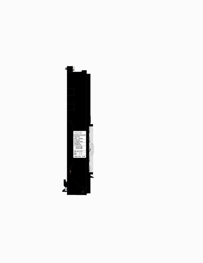
Instruction Manual MN013003EN

5. RELAY CONFIGURATION . . . . . . . . . . . . . . . . . . . . . . . . . . . . . . . . . . . . . . . . . . 16
6. PXR COMMUNICATION FEATURES. . . . . . . . . . . . . . . . . . . . . . . . . . . . . . . . . 17
         6.1 Integrated Modbus-Remote Terminal Unit (RTU) Port. . . . . . . . . . . . . . . . . . . . . . . . . 17
         6.2 USB Port. . . . . . . . . . . . . . . . . . . . . . . . . . . . . . . . . . . . . . . . . . . . . . . . . . . . . . . . 17
         6.3 External Communications Adapter Modules (CAMs). . . . . . . . . . . . . . . . . . . . . . . 17

7. IMPORTANT SYSTEM COMPONENTS . . . . . . . . . . . . . . . . . . . . . . . . . . . . . . . 17
         7.1 Potential Transformer (PT) Module . . . . . . . . . . . . . . . . . . . . . . . . . . . . . . . . . . . . 17
         7.2 Auxiliary Power. . . . . . . . . . . . . . . . . . . . . . . . . . . . . . . . . . . . . . . . . . . . . . . . . . . 17
         7.3 Power Xpert Protection Manager (PXPM) Configuration Software. . . . . . . . . . . . 17

8. SECONDARY WIRING TERMINALS ASSOCIATED WITH THE PXR TRIP UNIT.18
9. TESTING THE TRIP UNIT AND CIRCUIT BREAKER. . . . . . . . . . . . . . . . . . . . . . 18
         9.1 Functional Opening Test (Local) via Display. . . . . . . . . . . . . . . . . . . . . . . . . . . . . . 18
         9.2 Functional Current Testing (Remote) via USB/PXPM. . . . . . . . . . . . . . . . . . . . . . . 18
         9.3 Current Sensor Test (Remote) via USB/PXPM . . . . . . . . . . . . . . . . . . . . . . . . . . . 19
         9.4 Testing for Ground Fault Trip Units – Primary Injection. . . . . . . . . . . . . . . . . . . . . 19

10. MAINTENANCE OF THE PXR TRIP UNIT. . . . . . . . . . . . . . . . . . . . . . . . . . . . . 20
         10.1 Replacing the Battery. . . . . . . . . . . . . . . . . . . . . . . . . . . . . . . . . . . . . . . . . . . . . 20
         10.2 Replacing the Trip Unit. . . . . . . . . . . . . . . . . . . . . . . . . . . . . . . . . . . . . . . . . . . . 20

11. RECORD KEEPING . . . . . . . . . . . . . . . . . . . . . . . . . . . . . . . . . . . . . . . . . . . . . . 21
12. REFERENCES – SERIES NRX WITH PXR . . . . . . . . . . . . . . . . . . . . . . . . . . . . 22
APPENDIX A – MODBUS COMMUNICATION PORT. . . . . . . . . . . . . . . . . . . . . . . 23
         A.1 Viewing/Setting Modbus Setpoints. . . . . . . . . . . . . . . . . . . . . . . . . . . . . . . . . . . 23
         A.2 Network Communication Protocol. . . . . . . . . . . . . . . . . . . . . . . . . . . . . . . . . . . . 23
         A.3 Modbus Register Map. . . . . . . . . . . . . . . . . . . . . . . . . . . . . . . . . . . . . . . . . . . . . 23

APPENDIX B – TROUBLESHOOTING. . . . . . . . . . . . . . . . . . . . . . . . . . . . . . . . . . . 40

            PXR 20/25 Trip Unit for Series NRX User Manual Power Xpert® Release Trip Units MN013003EN July 2021 www.eaton.com                         iii
Instruction Manual MN013003EN

                      WARNING                                                                   WARNING
              Dangerous Electrical Voltage!                           Electrical shock or burn injury can occur when working
                                                                      on power systems. Always turn off the main power that
Do not attempt to install or perform maintenance on                   is supplying the circuit breaker before conducting tests.
equipment while it is energized. Death or severe injury               Test out of the cell, if possible.
can result from contact with energized equipment.
Always verify that no voltage is present before proceed-                                         CAUTION
ing. Always follow safety procedures. Eaton is not lia-
ble for misapplication or misinstallation of its products.            Exercise care when replacing the battery to ensure that it is
                                                                      installed correctly. Accidentally installing the battery in the
Observe all recommendations, notes, cautions, and                     reverse direction will not harm the trip unit nor the battery,
warnings related to the safety of personnel and equip-                but will defeat the function of the battery.
ment. Observe and comply with all general and local
health and safety laws, codes, and procedures.                                                 IMPORTANT
                                                                      Auxiliary power is not required to provide current protection
                      WARNING                                         features. Protection is active well below any overload. The
Do not attempt to install, test, or perform maintenance               trip unit begins to power-up at very low levels of current at
on equipment while it is energized. Death or severe                   approximately NF frame = 60 A, RF Frame = 100 A. The
personal injury can result from contact with energized                display will power up at NF frame = 140 A, RF frame =
equipment. De-energize the circuit and disconnect the                 200 A.
circuit breaker before performing maintenance or tests.
Any tripping operation will cause disruption of service
and possible personal injury, resulting in the unnec-
essary switching of connected equipment. Testing a
circuit breaker while it is in-service and carrying load
current is not recommended. Testing of a circuit breaker
that results in the tripping of the circuit breaker should
be done only with the circuit breaker in the test or dis-
connected cell positions or while the circuit breaker is
on a test bench.

iv             PXR 20/25 Trip Unit for Series NRX User Manual Power Xpert® Release Trip Units MN013003EN July 2021 www.eaton.com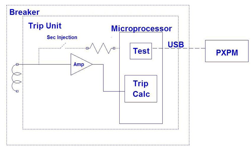
1. Introduction
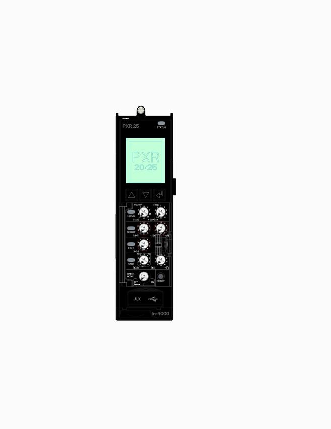
1. Introduction Figure 1. The PXR Trip Unit.
1.1 Introduction to the PXR 20/25
The Power Xpert Release (PXR) 20/25 trip unit, along with
current sensors and a trip actuator, is the subsystem of a
circuit breaker which provides the protective function. The
PXR analyzes signals from the current sensors. If current
level and time delay settings are exceeded, then the PXR
trip unit will trip the circuit breaker. The automatic over-
load and short circuit tripping characteristics for a specific
circuit breaker are determined by the current rating and
user selected protection settings. There is no mechanical
or direct magnetic action between the primary current and
the mechanical tripping parts of the circuit breaker. External
control voltage is not required for current protection func-
tionality.
The PXR trip unit consists of two modules, the frame mod-
ule and the control module. The control module contains
a microcontroller that performs true RMS current sensing
measurements and calculations for protection. It may be
replaced in the field. The frame module is matched to the
ratings of the circuit breaker and permanently attached to
the circuit breaker frame. It should not be removed or
exchanged.
PXR 20/25 Trip Unit for Series NRX User Manual Power Xpert® Release Trip Units MN013003EN July 2021 www.eaton.com 11. Introduction
The current sensors are internal to the circuit breaker frame Figure 2. Series NRX-NF and NRX-RF Circuit Breakers.
and consist of two coils; one coil on an iron core and one
coil on an air core (Rogowski coil). As current begins to
flow through the circuit breaker, the iron core coil gener-
ates a secondary current which powers the trip unit. At the
same time, the air core coil provides signals which are pro-
cessed to determine the current through the circuit breaker.
The mechanical action required to initiate tripping of the
circuit breaker is provided by a special low-energy trip actua-
tor. This trip actuator is an integral part of the circuit breaker
mechanism which also includes a charging handle, and
manual “Open” and “Close” buttons. The trip actuator is
automatically reset by the mechanism.
The wiring diagrams show how certain functions of the trip
unit are connected to external circuits. All wiring is landed
on the secondary contact system directly above the circuit
NRX-NF
breaker. See Section 11 - “References” for the technical
document number that contains the wiring diagrams.
The PXR trip units are listed by Underwriters Laboratories
Inc. (UL) and Canadian Standards Association (CSA) for use
in Series NRX-NF and Series NRX- RF circuit breakers. All
PXR units have also passed the IEC 60947-2 test program
that includes EMC testing according to Appendix F. All trip
units meet the low voltage and EMC directives and carry
the CE mark.
For more on Series NRX low voltage power breakers go to
www.eaton.com/seriesnrx
NRX-RF
2 PXR 20/25 Trip Unit for Series NRX User Manual Power Xpert® Release Trip Units MN013003EN July 2021 www.eaton.com2. Protection and Metering Features
2. Protection and Metering Features
2.1 Trip Unit Functions
Table 1. Trip Unit Functions.
Trip Unit Catalog Protection
Type Number Style High Load Alarm Ground Fault Maintenance Mode Modbus RTU
PXR20V000L00C LSI •
PXR20V000L00M LSI • •
PXR20V000LG0C LSIG •
PXR20V000LG0M LSIG • •
PXR 20
PXR20V000LGAC LSIGR • •
PXR20V000LGAM LSIGR • • •
PXR20V000L0AC LSIR • •
PXR20V000L0AM LSIR • • •
PXR25V000L00M LSI • •
PXR25V000LG0M LSIG • •
PXR 25
PXR25V000L0AM LSIR • • •
PXR25V000LGAM LSIGR • • •
PXR 20/25 Trip Unit for Series NRX User Manual Power Xpert® Release Trip Units MN013003EN July 2021 www.eaton.com 32. Protection and Metering Features
2.2 Protection Features
Table 2. Protection Features.
Protection PXR 20 PXR 25
Slope I2t, I4t, I0.5t, It I2t, I4t, I0.5t, It
Long Delay Pickup (Ir) x (In) 0.4, 0.5, 0.6, 0.7, 0.75, 0.8, 0.9, 0.95, 0.4, 0.5, 0.6, 0.7, 0.75, 0.8, 0.9, 0.95,
0.98, 1.0 0.98, 1.0
Long Delay Protection (L)
Long Delay Time @ 6 x (Ir) Seconds 0.5, 1, 2, 4, 7, 10, 12, 15, 20, 24 0.5, 1, 2, 4, 7, 10, 12, 15, 20, 24
Thermal Memory Included Included
High Load Alarm % x (Ir) Fixed Level 85% Fixed Level 85%
Short Delay Slope Flat, I2t Flat, I2t
Short Delay Pickup x (Ir) 1.5, 2, 2.5, 3, 4, 5, 6, 7, 8, 10 1.5, 2, 2.5, 3, 4, 5, 6, 7, 8, 10
Short Delay Protection (S) Short Delay Time at 8 x (Ir) I t
2
Seconds 0.1, 0.3, 0.4, 0.5 0.1, 0.3, 0.4, 0.5
Short Delay Time Flat Seconds 0.0, 0.1, 0.2, 0.3, 0.4, 0.5 0.0, 0.1, 0.2, 0.3, 0.4, 0.5
Zone Interlock Enable/Disable Enable/Disable
Instantaneous Protection (I) Instantaneous x (In) Off, 2, 4, 5, 6, 7, 8, 10, 12, 15 Off, 2, 4, 5, 6, 7, 8, 10, 12, 15
Neutral Protection 4th Pole or External Neutral Trip % x (Ir) 0 (Off), 60, 100 0 (Off), 60, 100
Ground Fault Pickup x (In) Off, 0.2, 0.4, 0.6, 0.8, 1.0 Off, 0.2, 0.4, 0.6, 0.8, 1.0
Ground Fault Alarm x (In) 0.2, 0.4, 0.6, 1.0 0.2, 0.4, 0.6, 1.0
Ground Fault Delay at 0.625 x Seconds 0.1, 0.2, 0.3, 0.4, 0.5 0.1, 0.2, 0.3, 0.4, 0.5
Ground (Earth) Fault Protection (I ) I2t
n
(Option G)
Ground Fault Delay Flat Seconds 0.1, 0.2, 0.3, 0.4, 0.5 0.1, 0.2, 0.3, 0.4, 0.5
Zone Interlock Enable/Disable Enable/Disable
Thermal Memory Included Included
Setting Enable or Disable/Remote Enable or Disable/Remote
Maintenance Mode Protection Relay Contact for Remote
Included Included
(ARMS) (Option R) Indication of Mode
Maintenance Mode Pickup x (ln) 2.5, 4.0, 6.0, 8.0, 10.0 2.5, 4.0, 6.0, 8.0, 10.0
General Trip Unit Over Temperature Trip Degrees 85°C (185°F) Fixed 85°C (185°F) Fixed
If I4T slope is selected not all times are available, consult time-current curves
PXR 20/25 is limited to 1200A in ANSI/UL frames to comply with standards.
4 PXR 20/25 Trip Unit for Series NRX User Manual Power Xpert® Release Trip Units MN013003EN July 2021 www.eaton.com2. Protection and Metering Features
2.3 Current and Voltage Metering Data
Table 3. Current and Voltage Metering Data.
Current Metering Units Accuracy Notes
IA, IB, IC, IN, IG Amperes ±1% of Reading
Minimum IA, IB, IC, IN, IG Amperes ±1% of Reading Group Values Held Until Reset
Maximum IA, IB, IC, IN, IG Amperes ±1% of Reading Group Values Held Until Reset
THD for IA, IB, IC , IN 10% of Reading Firmware version 02.02 and later
Voltage Metering Units Accuracy Notes
VAB, VBC, VCA Volts ±1% of Reading Line to Line Voltage
Minimum VAB, VBC, VCA Volts ±1% of Reading Group Values Held Until Reset
Maximum VAB, VBC, VCA Volts ±1% of Reading Group Values Held Until Reset
THD for VAB, VBC, VCA 10% of Reading Firmware version 02.02 and later
VAN, VBN, VCN Volts ±1% of Reading Line to Neutral Voltage
Minimum VAN, VBN, VCN Volts ±1% of Reading Group Values Held Until Reset
Maximum VAN, VBN, VCN Volts ±1% of Reading Group Values Held Until Reset
THD for VAN, VBN, VCN 10% of Reading Firmware version 02.02 and later
Accuracy applicable for 10% to 120% of In at 25°C (77°F).
Accuracy applicable for the voltage range of 34 to 690 Vac at 25°C (77°F).
Only the PXR25 has this function.
PXR 20/25 Trip Unit for Series NRX User Manual Power Xpert® Release Trip Units MN013003EN July 2021 www.eaton.com 52. Protection and Metering Features 2.4 Power and Energy Metering Data. Table 4. Power and Energy Metering Data. Power Metering Units Accuracy Notes Real kW ±2% of Reading Approximately 1 Second Update Apparent kVA ±2% of Reading Approximately 1 Second Update Reactive kvar ±2% of Reading Approximately 1 Second Update Real Demand kW ±2% of Reading Fixed Window of 5 Minutes Apparent Demand kVA ±2% of Reading Fixed Window of 5 Minutes Reactive Demand kvar ±2% of Reading Fixed Window of 5 Minutes Real Demand (Peak) kW ±2% of Reading Value Held Until Reset Apparent Demand (Peak) kVA ±2% of Reading Value Held Until Reset Reactive Demand (Peak) kvar ±2% of Reading Value Held Until Reset Power Factor - Approximately 1 Second Update Energy Metering Units Accuracy Notes Real Total kWh ±2% of Reading Forward + Reverse Real Net kWh ±2% of Reading Forward - Reverse Real Forward kWh ±2% of Reading Delivered by Source to Load Real Reverse kWh ±2% of Reading Delivered by Load to Source Apparent kVAh ±2% of Reading Energy Reactive Received kvarh ±2% of Reading Reactive Energy in Quadrants 1 + 2 Reactive Delivered kvarh ±2% of Reading Reactive Energy in Quadrants 3 + 4 Reactive Net kvarh ±2% of Reading kvarh Delivered - kvarh Received Reactive Total kvarh ±2% of reading kvarh Delivered + kvarh Received Accuracy applicable for 10% to 120% of In at 25°C (77°F). Accuracy applicable for the voltage range of 34 to 690 Vac at 25°C (77°F). Only PXR25 has this function. In firmware version 02.02 and later, the Power Factor calculation method can be selected as IEC, IEEE or Alternate IEEE under Edit Settings menu. 2.5 Time Current Curves The Time-Current Curves (TCC) for the PXR 20/25 when used in Series NRX circuit breakers are referenced below. All protection settings shall be made by following the rec- ommendations of the specifying engineer in charge of the installation. Time Current Curves for Series NRX Type NF and RF Frame with PXR 20/25 Trip Units are found in document AD 013001EN Use the link/path below to access time-current curves at Eaton’s Web site: http://www.eaton.com/TCC 6 PXR 20/25 Trip Unit for Series NRX User Manual Power Xpert® Release Trip Units MN013003EN July 2021 www.eaton.com
3. Power Xpert® Release Trip Units

3. Power Xpert® Release Trip Units                                      3.1 Status Indicator
                                                                        All PXR trip units have an indicator at the top right labeled
The PXR 20/25 is located on the front and to the left side              “STATUS”. During normal operation, this indicator blinks
of the circuit breaker. It is encased in a housing which                green (on and off approximately once each second), indicat-
provides protection to the electronics as well as providing             ing that the trip unit is operating normally.
an interface for a user to configure protection settings and
monitor operation. Details of the interface and operation               Figure 4. Status Indicator.
are contained in the sections which follow. Certain features
are available only in selected PXR 20/25 trip unit styles.

Figure 3. PXR Trip Unit Front Face.
                                                                                                                              Status
                                                                                                                              Indicator

                                                       Status
                                                       Indicator

                                                                        The status indicator blinks red if the trip unit detects an
                                                                        internal problem. This indicates a problem with the trip
                                                                        actuator coil, a firmware error, calibration error, or a mecha-
                                                                        nism error. Immediate action must be taken to rectify the
                                                                        problem and/or replace the trip unit. See Appendix B -
                                                                        “Troubleshooting” for details.
                                                                        When the status indicator remains off, there is no auxiliary
                                                                        power applied or insufficient primary current to power the
                                                                        trip unit. This does not indicate a malfunction. The status
                                                                        indicator will resume blinking when auxiliary power is sup-
                                                                        plied or breaker load increases.
                                                     Display and
                                                     Navigation
                                                     Buttons
                                                                        3.2 Display and Navigation Buttons
                                                                        The PXR trip unit has a display on the front of the trip unit.
                                                                        This display provides information such as metered values,
                                                                        events, and the method to select certain configuration
                                                                        options. Information is presented on the display in either
      Pickup/                                                           English or simplified Chinese. Back lighting is included with
 Cause-of-Trip                                                          a power saving feature that after 30 seconds of inactivity
   Indicators                                        Rotary
                                                     Switches           will turn the backlight off.
                                                                        There are three buttons below the display (see Figure 5).
                                                                        They are used to control what information is shown on the
                                                                        display and to select certain configuration options:

                                                                        Figure 5. Display and Navigation Buttons.
 Maintenance                                         Reset
 Mode Switch                                         Button

                                                                                  Up Arrow Button      Used to move up in the menu display
       USB and                                                                                         screens or increase an adjustment
Auxiliary Power                                                                                        value.
   Under Door                                        Door
                                                                                  Down Arrow Button Used to move down in the menu
                                                                                                    display screens or decrease an adjust-
     Battery                                                                                        ment value.
        Tray
                                                                                  Enter Button         Used to enter the menu or setting and
                                                                                                       can also go back to the previous menu

          PXR 20/25 Trip Unit for Series NRX User Manual Power Xpert® Release Trip Units MN013003EN July 2021 www.eaton.com                    7
3. Power Xpert® Release Trip Units
When the PXR trip unit is initially powered-up, the display The appropriate cause-of-trip indicator illuminates when a
will briefly show a loading screen and then change to the current level pickup setting is exceeded. After a trip event,
“Main” menu. During this time, the trip unit is already func- the indicator blinks (one second on, three seconds off) and
tioning and performing protection operations. Depending the cause will be shown on the display if auxiliary power is
on the trip unit style, there are up to 13 submenu selections applied. The indicators and the display can be cleared by
from the main menu. Each submenu can be accessed pressing the RESET button.
by highlighting the appropriate submenu by pressing the
Down or Up Arrow buttons, then the Enter button. A com- Following is a list of conditions detected and displayed by
plete map of the information and navigation is included in the cause-of-trip indicators.
IL0131128EN. ● “LONG” – Solid indicates Long Delay pickup.
In firmware version 02.02 and later, digitally configured set- Blinking indicates a Long Delay trip or over-
points are password protected to reduce risk of unauthor- temperature trip has occurred.
ized changes. You must enter the correct password (factory ● “SHORT” – Short Delay trip or mechanism error.
default is “0000”) in the “Edit Settings” menu to change
the following settings: ● “INST” – Instantaneous trip, Making Current
Release trip, High Instantaneous trip, or
● Language Maintenance Mode trip has occurred.
● Communication configuration (for on-board Modbus and ● “GND” – Ground trip or Ground alarm condition has
external CAM) occurred.
● Thermal Memory
● Long Delay Curve selection (I2t, I4t, I0.5t, It) 3.4 Rotary Switches
Depending on the trip unit style, up to 8 switches can
● Neutral pickup (100%, 60%, off) be found on the trip unit’s front panel. The top 7 rotary
● Power Feed (forward or reverse) switches set protection settings using a surrounding legend
indicating the value. These are the core protection settings.
● ZSI – Zone Selective Interlock (on or off) Each switch has ten positions and is set to achieve the
● Maintenance Mode pickup (2.5, 4.0, 6.0, 8.0, 10.0 x In) appropriate trip-curve response. The “PICKUP” switches
set the levels as a function of the breaker ratings. The
● Edit Password “TIME” switches set the response in seconds. Each switch
can be set using a small screwdriver, the arrow pointing to
● Set Time the selected value. When a change is made to the rotary
switches, the display will temporarily change to indicate all
3.3 Pickup/Cause-of-Trip Indicators of the selected settings.
There are four pickup/cause-of-trip indicators on the face of
the trip unit labeled “LONG”, “SHORT”, “INST”, and “GND”.
3.5 Maintenance Mode Switch
The PXR trip unit incorporates the Arc Flash Reduction
Figure 6. Pickup/Cause-of-Trip Indicators and Reset. Maintenance System™ (ARMS). If equipped, this switch
is labeled “MAINT. MODE” and has two positions labeled;
“OFF/Remote” & “ON”. A blue colored ring surrounding the
maintenance mode switch is illuminated when ARMS is
enabled.
Figure 7. Maintenance Mode Switch
Pickup/
Cause-of-Trip
Indicators
Maintenance
Mode Switch
Reset 3.6 Reset
The button labeled “RESET”, located in the lower right face
of the trip unit, can be depressed to reset the cause of trip
indicators (see Figure 6).
8 PXR 20/25 Trip Unit for Series NRX User Manual Power Xpert® Release Trip Units MN013003EN July 2021 www.eaton.com4. PXR Protection Settings
3.7 Tamper-Resistant Cover 3.11 Battery
A clear, plastic cover is provided which allows the settings At the bottom of the trip unit is a small tray which holds
to be viewed but not changed. Unauthorized access to the battery. When the trip unit is not powered, this battery
change settings can be prevented by the insertion of a supports the cause-of-trip indicators. A battery icon at the
standard sealing wire through the security holes in order to bottom of the display indicates remaining battery life. The
meet applicable tamper-resistant requirements. battery plays no part in the protection functions of the trip
system. This battery is the standard type CR 2032 coin-cell.
3.8 Door
Near the bottom of the PXR trip unit, there is a small door Figure 10. Battery Tray.
with “AUX” and the Universal Serial Bus (USB) icon. The
door can be opened downward to expose the temporary
auxiliary power port and the micro-B USB port. Battery Tray
Figure 8. Trip Unit Door.
In Rating
Trip Unit Door
3.12 In Rating
This legend shows the In rating of the breaker. It is also
shown on the lower left corner of the display.
3.13 Side Labels
3.9 USB The side of the trip unit has agency certification, model, and
The USB is a micro-B USB connector utilizing USB 2.0 manufacturing information printed on a label.
protocol. This USB connection may be used in conjunction
with the Power Xpert Protection Manager software to con-
figure and monitor the trip unit. A USB connection will also Figure 11. Typical PXR Trip Unit Side Label.
typically provide power from the host side of the USB cable
to power up the trip unit when another source of auxiliary
power is not available. This connection is intended for tem-
porary use while a user is configuring or monitoring the trip
unit.
Figure 9. Behind the Trip Unit Door.
Auxiliary USB Port
Power
3.10 Temporary Auxiliary Power
The two-pin socket under the left side of the door (see
Figure 9) accepts the mating connector from a Digitrip auxil-
iary power module (Catalog Number: PRTBAPMDV for U.S.
power sockets, DTAUXPMEU for European power sockets,
or DTAUXPMUK for U.K. power sockets). This power source
may be used to power the trip unit when another source of
auxiliary power is not available. This connection is intended
for temporary use while a user is configuring or monitoring
the trip unit.
PXR 20/25 Trip Unit for Series NRX User Manual Power Xpert® Release Trip Units MN013003EN July 2021 www.eaton.com 94. PXR Protection Settings
4. PXR Protection Settings 4.1.2 Long Delay Thermal Memory
In addition to the standard Long Delay protection, a Long
The PXR trip unit protection settings are designed to be Time Memory (LTM) function is supported. This protects
easily customized to any application. Settings for long delay load circuits from the effects of repeated overload condi-
pickup, long delay time, short delay pickup, short delay tions. LTM is configured using the display and navigation
time, instantaneous pickup, ground fault pickup, and ground buttons or using the Power Xpert Protection Manager soft-
fault time are all independently configurable. These func- ware.
tions are set using rotary switches on the front of the trip
As an example, if a circuit breaker is closed soon after a
unit. Additional options are chosen using the display and
Long Delay trip, and the current again exceeds the Long
navigation buttons or by using the Power Xpert Protection
Delay setting (Ir), the LTM automatically reduces the time to
Manager configuration software.
trip to allow for the fact that the load conductor temperature
Please refer to Table 2 for a detailed list of the configurable is already higher than normal because of the prior overload
setting values. condition. Each time the overload condition is repeated,
the LTM causes the circuit breaker to trip in a progressively
Before placing any circuit breaker in operation, set each trip shorter time. When the load current returns to normal, the
unit protection setting to the values specified by the engi- LTM begins to reset (after about ten minutes it will have
neer responsible for the installation. reset fully) so the next long delay trip time will again corre-
spond to the setting value.
4.1 Long Delay Pickup and Time Setting
The PXR trip unit offers a wide range of settings for Long 4.2 Short Delay Pickup and Time Settings
Delay Pickup (LDPU or Ir). This setting ranges from 0.4 to Settings for Short Delay Pickup (SDPU or Isd) are expressed
1.0 and is expressed as a multiple of the frame’s current rat- as multiples ranging from 1.5 to 10 for the long delay pickup
ing (In). The pickup value for Long Delay is 105% to 115% current setting (Ir).
of the calculated value to ensure that the circuit breaker can
carry the full rating of (Ir), without tripping. The short delay time (tsd) is selected in conjunction with one
of two short delay slopes, flat, or I2t. There are six settings
The long delay time settings range from 0.5 to 24 sec- for the flat curve and four settings for I2t, ranging from 0
onds. They represent the total clearing times when the seconds (minimum time) to 0.5 seconds.
current value equals six times Ir. All times are referenced
from the top of the tolerance band, ensuring that the time The I2t response curve will provide a longer time delay
never exceeds that maximum setting. When an I4t slope is for currents below eight times Ir as compared with a flat
selected, an overload creates a very long time delay which response curve. For currents greater than eight times Ir, the
could exceed breaker ratings. Therefore, when a time delay I2t response flattens out to the flat response.
above seven seconds is selected, seven seconds will be
If a short delay causes the circuit breaker to trip, the
used instead.
“SHORT” indicator will be illuminated and the “Short Delay
If a long delay causes the circuit breaker to trip, the Trip” message will be displayed if auxiliary power is present.
“LONG” indicator will be illuminated and the “Long Delay”
The Zone Selective Interlocking (ZSI) feature may affect
message will be displayed if auxiliary power is present.
the tripping times for the short delay protective function.
Please refer to the section on ZSI.
4.1.1 Long Delay Slope Selection
The I2t setting is the factory default curve for long delay. 4.3 Instantaneous Pickup Setting
The curve can be changed using the display and navigation The instantaneous (Ii) setting is expressed as multiples rang-
buttons to several alternative curves to better match the ing from 2 to 15 of the In value or can be set to “OFF”. The
requirements for protection and coordination. instantaneous protection trips the breaker with no inten-
● I0.5t - Slightly Inverse Time Curve tional time delay.
● It - Moderately Inverse Time Curve
4.4 Ground Fault Settings
● I2t - Inverse Time Current Curve, used in standard When the PXR 20/25 trip unit includes ground fault protec-
distribution protection (factory default). tion features, the distribution system characteristics (such
● I4t - Extremely Inverse Time Current Curve, A as system grounding, number of sources, and number
steep protective slope for coordination with and location of ground points) must be considered along
fuses or for special types of loads. with the manner and location in which the circuit breaker
is applied to the system. To ensure correct ground fault
equipment performance and compliance, you must conduct
the field testing required to comply with country or regional
requirements.
10 PXR 20/25 Trip Unit for Series NRX User Manual Power Xpert® Release Trip Units MN013003EN July 2021 www.eaton.com4. PXR Protection Settings
4.4.1 Ground Fault Pickup 4.4.4 Ground Fault Relay
The PXR trip unit provides flexibility in detecting and acting If the Ground Fault Alarm option is selected on the LSIG
on ground currents. A ground fault alarm can provide an or LSIGR style trip units, a red ground Alarm indicator will
early warning of a ground fault condition and a ground fault illuminate to show the presence of ground current in excess
trip can provide protection under these conditions. Three of the Ground Alarm setting. The trip unit will energize an
modes of operation are selectable from the front of the trip alarm relay upon this condition if auxiliary power is present.
unit. The indicator and relay will reset automatically when the
ground current reduces to a value less than the ground fault
1. The ground detection may be turned off by setting the pickup setting.
rotary switch to “OFF”.
If the Ground Fault Trip option is selected, the alarm relay
2. The ground fault detection pickup level with an alarm can be configured to indicate when the circuit breaker has
only action may be selected using the rotary switch. tripped on a ground fault. You must then push the “RESET”
With the alarm-only selection, four levels of pickup level button in order to reset the relay contact.
are available. This set of pickup levels is labeled “Alarm”.
3. The ground fault detection pickup level with an action
of trip may also be selected using the rotary switch. 4.5 Ground Fault Sensing
With detect and trip selection, five levels of pickup level The PXR 20/25 trip unit provides for three modes of sensing
are available, this set is labeled “Trip”. If a ground fault to detect ground fault currents: Residual, Source Ground,
causes the circuit breaker to trip, the “GND” indicator and Zero Sequence. The mode (Residual or Source/Zero
will be illuminated and the “Ground Fault Trip” message Seq) is selected using the display and navigation buttons
will be displayed when auxiliary power is present. or by using the configuration software. Neutral protec-
tion is provided independent of the Ground Fault function.
Note: For ANSI/UL breakers, the pickup level will have a For 3-pole breakers without a Neutral Sensor, jumper the
maximum of 1200A per standards. Neutral Sensor input.
Note: Your application may require ground fault protec-
tion. Please consider NEC and/or applicable codes 4.5.1 Residual Current Sensing
to determine required mode of operation (“OFF”, Residual sensing is the standard mode of ground fault sens-
“Alarm”, or “Trip”) ing in Series NRX circuit breakers. This mode uses one
current sensor on each phase conductor and one on the
neutral for a four-wire system. This mode of sensing sums
4.4.2 Ground Fault Time the outputs of the three or four individual current sensors.
The PXR trip unit provides selection for two different ground If the sum is zero, then no ground fault exists. Residual
fault slopes: a fixed time (flat) or I2t response. The slope ground fault sensing features are adaptable to main and
should be chosen to match selective coordination needs. feeder circuit breaker applications. If an external neutral
The I2t response provides a longer time delay for current sensor is used with reverse feed breaker applications, the
below 0.625 x In than the fixed time (flat) response. proper polarity of the neutral needs to be considered.
The time delay and slope are selected on a single rotary
switch. The I2t response time selections are indicated with 4.5.2 Source Ground Sensing
an asterisk (*) while the fixed time (flat) response time
selections are indicated without an asterisk. Both have a The ground return method is usually applied when ground
range from 0.1 seconds to 0.5 seconds. fault protection is desired only on the main circuit breaker
in a simple radial system. This method is also applicable to
double-ended systems where a mid-point grounding elec-
4.4.3 Ground Fault Thermal Memory trode is employed.
In addition to standard ground fault protection, the PXR trip For this mode of sensing, a single 400 A current sensor
unit also has a ground fault memory function that serves mounted on the equipment-bonding jumper will directly
to protect loads in the event of a sputtering arc to ground. measure the total ground current flowing in the grounding
Without this function, the ground fault protection timer conductor. Setting the ground fault type will enable this
resets each time the arc goes out, so that a sputtering protection. Refer to Table 5 for sensor style number.
fault may not trip the circuit breaker. With the ground fault
memory function, the trip unit “remembers” the sputter-
ing ground current. The memory decays with time, the 4.5.3 Zero Sequence Sensing
time interval equals 6.25 times the ground fault time. For Zero Sequence sensing, also referred to as vectorial sum-
example, with a 0.4 second setting, the function will reset mation, is applicable to mains, feeders, and special schemes
in 2.5 seconds. involving zone protection.
PXR 20/25 Trip Unit for Series NRX User Manual Power Xpert® Release Trip Units MN013003EN July 2021 www.eaton.com 114. PXR Protection Settings
4.5.4 Ground Sensors
Table 5. Ground Sensors.
Ground (Earth) Sensing Method Instruction Leaflet Number Sensor Style IZMX Type Code
Residual NF Frame IL0131090EN 5721B76G12 IZMX-CT16-N
Residual RF Frame IL0131094EN 70C1718G11 IZMX-CT40-N
Source Ground or Zero Sequence IL0131089EN 70C1527G04 IZMX-CT-NGS
4.6 Maintenance Mode 4.7 High Instantaneous
The PXR trip units support Eaton’s Arc Flash Reduction The PXR trip unit provides a high instantaneous trip function
Maintenance System™ (ARMS), also referred to as that will trip the circuit breaker at the withstand rating of
Maintenance Mode. When enabled, the trip unit will trip the the circuit breaker frame. This function is factory set within
breaker with no intentional delay whenever the configured the frame module and reacts to the peak current level. It
pickup level is exceeded. When enabled, the Maintenance is always active regardless of the user’s instantaneous
Mode function operates regardless of the Instantaneous adjustment selection, including “OFF”. The instantaneous
settings. If Maintenance Mode causes the circuit breaker to (“INST”) indicator shows this cause of trip.
trip, the “INST” indicator will be illuminated and the “ARMS
Trip” message will be displayed if auxiliary power is present. All Series NRX NF frame modules have an High
Instantaneous trip feature. Selected Series NRX RF frame
The Maintenance Mode pickup level setting is configured modules also have the High Instantaneous feature.
using the display and navigation buttons. For the NF frame-
and the RF frame the settings are 2.5, 4.0, 6.0, 8.0 or 10.0
(x ln). The adjustable current settings allow for different 4.8 Making Current Release (MCR)
levels of protection. A higher level may be needed when, All PXR trip unit styles have a Making Current Release
for example, another load fed from this breaker may contain (MCR) function. This safety feature prevents the circuit
motors that are being started and create large inrush cur- breaker from being closed and latched-in on a faulted circuit.
rents over the lowest trip current level. The selection of one The MCR is enabled only for the first two cycles of current
of the reduction settings should be determined and selected following the initial circuit breaker closing operation. The
by a person who is experienced in power system analysis. circuit breaker will trip with no delay and the instantaneous
(“INST”) indicator will show the cause of trip.
4.6.1 Enabling Maintenance Mode This non-adjustable release is set by the frame module of
the circuit breaker. Refer to time current curves for specific
There are three ways to enable the Maintenance Mode values.
function, locally, remotely using a contact, or remotely
using communications. A blue colored ring surrounding the
switch always illuminates to confirm when the function is 4.9 Zone Selective Interlocking (ZSI)
enabled. An additional normally open contact is available The Zone Selective Interlocking (ZSI) function is provided
on the secondary terminal block which can also be used to on all trip units and can be enabled or disabled through
indicate when Maintenance Mode is active. the menu system or Power Xpert Protection Manager soft-
For locally actuating the Maintenance Mode function, use ware. ZSI functions in conjunction with the Short Delay and
the selector switch on the front of the trip unit. When in Ground Fault protection functions. ZSI provides the fastest
the ON position, Maintenance Mode is enabled and cannot possible tripping for faults within the zone of protection of
be turned-off remotely. the circuit breaker and also provides positive coordination
among all circuit breakers in the system (mains, ties, feed-
When this switch is in the OFF/Remote position, ers, and downstream circuit breakers).
Maintenance Mode can be remotely actuated by a contact
wired to the secondary terminal block of the breaker.
A third method to actuate Maintenance Mode is via commu-
nications. This can be done by a Communications Adapter
Module (CAM) or by the configuration software using the
USB port. When Maintenance Mode is enabled in either of
these ways, it must also be disabled via communications.
Moving the switch from “OFF/Remote” to “ON” and back
to “OFF/Remote” will not disable Maintenance Mode.
12 PXR 20/25 Trip Unit for Series NRX User Manual Power Xpert® Release Trip Units MN013003EN July 2021 www.eaton.com4. PXR Protection Settings
When ZSI is enabled, a fault within the zone of protec-
tion will immediately trip the breaker and send a signal to
upstream trip units to restrain them from tripping imme-
diately. The restraining signal causes the upstream circuit
breakers to follow their set coordination time delays so
that the service is interrupted to the isolated fault area only
while the fault is cleared in the shortest time possible.
The ZSI is wired using a set of three wires labeled Zone
In (Zin), Zone Out (Zout), and Zone Common (Zcom) on
the secondary terminals above the circuit breaker. These
signals are compatible will all Eaton circuit breakers which
have the ZSI function. The zone out signal is sent whenever
the ground fault pickup is exceeded or when the short delay
pickup value of two times Ir is exceeded. This provides
maximum selectivity for coordination with larger upstream
circuit breakers. For the furthest downstream breaker
the use of a self-interlocking jumper may or may not be
needed depending on the application. If immediate trip-
ping is desired on the last breaker the Zin on that breaker
can be left open while the Zout is wired to the Zin of the
breaker upstream from it. If a time delay is desired on the
last breaker then a jumper from the Zout of that breaker
should wired to the Zin of the same breaker to provide a
self-interlocking feature. Refer to Eaton Application Note
AP02602002E for detailed description and examples.
4.10 Event Recording and Waveform Capture
The PXR trip unit will record information surrounding events,
alarms, and trips into a set of logs. For simple events, only
the reason and a time-stamp (based on the trip unit’s real-
time clock) are stored. More important events additionally
store a snap-shot of real-time values (currents and voltages).
The most important events additionally store more informa-
tion, storing waveforms of current and voltage experienced
during the event.
Each log can store a set number of events and is managed
as a first-in first-out buffer (FIFO). As the information is
stored for the most recent event, the information from the
oldest event is eliminated.
PXR 20/25 Trip Unit for Series NRX User Manual Power Xpert® Release Trip Units MN013003EN July 2021 www.eaton.com 134. PXR Protection Settings
4.10.1 Event and Log Matrix
Table 6. Event and Log Matrix.
Trip Snapshot
Event Code &
Time-stamp
Waveform
Waveform
Waveform
Snapshot
Alarm
Alarm
User
Trip
Event Notes
200 10 10 1 1 6 Quantity Stored
User Initiated Capture ● USB or Network Triggered
Power Up - Clock OK ●
Power Up - Clock Bad ●
Event - Setpoints Download ●
Event - Enter Test Mode ●
Event - Exit Test Mode ●
Event - Test Complete ●
Event - Enter Maintenance Mode ● Indicator on Front Also Illuminates
Event - Exit Maintenance Mode ●
Event - Opened By Communications ● w/ CAM Supported Module, Spring Release and Shunt Trip
Event - Closed By Communications ●
Event - Time Change (if > 60 seconds) ● Previous Time Is Recorded
Alarm - Calibration ● ●
Alarm - Setpoints Fault ● ●
Alarm - Battery Low Voltage ● ●
Alarm - Low Control Voltage ● ●
Alarm - RTC Error ● ●
Alarm - NV Memory Error ● ●
Alarm - Watchdog Timer ● ●
Alarm - Long Delay Pickup (Test Mode) ● ●
Alarm - Ground Fault (Test Mode) ● ●
Alarm - Trip Actuator Fault ● ●
Alarm - Operations Count ● ●
Alarm - Long Delay Pickup ● ● ●
Alarm - Ground Fault ● ● ●
Alarm - Mechanism Error ● ● ●
Alarm - High Load ● ● ●
Trip - Over Temperature ● ●
Trip - Making Current Release ● ●
Trip - Test ● ●
Trip - Long Delay ● ● ●
Trip - Short Delay ● ● ●
Trip - Instantaneous ● ● ●
Trip - Ground ● ● ●
Trip - Maintenance Mode ● ● ●
Trip - Neutral ● ● ●
14 PXR 20/25 Trip Unit for Series NRX User Manual Power Xpert® Release Trip Units MN013003EN July 2021 www.eaton.com4. PXR Protection Settings
Table 7. Information Stored.
Event Code and Time-stamp Event Cause and Time-stamp
Status: Primary, Secondary
Alarm Snapshot or Trip Snapshot Current: IA, IB, IC, IN, IG
Voltages: VAB, VBC, VCA, VAN, VBN, VCN (PXR 25 Only)
Power: Watts, Vars, VA (PXR 25 Only)
Demand: Watts, Vars, VA (PXR 25 Only)
Temperature
Frequency
Power Factor
Operations Count
User Waveform or Alarm Waveform Waveform of: IA, IB, IC, IN, IG
Waveform of: VAB, VBC, VCA, VAN, VBN, VCN (PXR 25 Only)
1 Cycle (64 Data Points)
Trip Waveform Waveform: IA, IB, IC, IN, IG
Waveform of: VAB, VBC, VCA, VAN, VBN, VCN (PXR 25 Only)
6 Cycles (384 Data Points)
PXR 20/25 Trip Unit for Series NRX User Manual Power Xpert® Release Trip Units MN013003EN July 2021 www.eaton.com 155. Relay Configuration
5. Relay Configuration
There are 3 relays in the PXR frame module which are used to indicate status information to other systems. Reference sec-
tion 8 – Secondary Wiring Terminals Associated with the PXR Trip Unit for their connections on the terminal block. Note that
relays require auxiliary power to operate.
In firmware version 02.02 and later, the relays can be configured to indicate additional conditions. Configuration is conve-
niently done using Power Xpert Protection Manager software. Pick-up levels for High Load 1 Alarm, High Load 2 Alarm,
Ground Fault Pre-Alarm and Thermal Memory alarm are also configurable.
Description of Relay Operation:
Function
Name “The relay will close when … “ “The relay will open when … “
Overload Trip there was a Long or Over-temperature trip RESET button is pressed or communications reset command received
Neutral Trip there was a Neutral Current trip RESET button is pressed or communications reset command received
Short Delay Trip there was a Short Delay trip RESET button is pressed or communications reset command received
Instantaneous Trip there was an Instantaneous trip or MCR RESET button is pressed or communications reset command received
Short Circuit Trip there was a Short, Inst or Override trip RESET button is pressed or communications reset command received
Ground Fault Trip there was a Ground Fault trip RESET button is pressed or communications reset command received
Maint. Mode Trip there was a Maintenance Mode trip RESET button is pressed or communications reset command received
All Trips any of protective trip (Overload, Neutral, Short, Instantaneous, RESET button is pressed or communications reset command received
Ground, Maint. Mode)
High Load 1 current flow is greater than set point (adjustable from 50% to current flow falls 5% below the set point
120% of Ir)
High Load 2 current flow is greater than set point (adjustable from 50% to current flow falls 5% below the set point
120% of Ir)
High Temperature temperature exceeds 5C below the level of the temperature trip temperature falls 5C below the setting
setting
Ground Fault Pre-Alarm ground current is greater than the set point (adjustable from ground current falls 5% below the set point
50% to 100%)
Thermal Memory the Thermal Memory value is greater than set point (adjustable Thermal Memory falls 5% below the set point
from 50% to 100%)
Watchdog auxiliary power is active and the trip unit is healthy and operat- there is an error in the trip unit from any of the self-diagnostics
ing
Low Battery the battery is below 1 bar (20%) the battery value is 1 bar (20%) or higher
Internal (HW) Fault there is an internal fault detected RESET button is pressed or communications reset command received
Setpoint Mismatch a setpoint in the trip unit does not match the CAM’s copy RESET button is pressed or if a reset command sent by any com-
munication
Breaker Health Alarm the health value is below 25% the health value is at or above 25%
Communication Error any external communications error occurs RESET button is pressed or communications reset command received
All Faults any of Internal Fault, Setpoint Mismatch, Breaker Health Alarm, all of Internal Fault, Setpoint Mismatch, Breaker Health Alarm, or
or Communication Error faults Communication Error are inactive
Aux Contact breaker is closed breaker is open
Bell Contact breaker is tripped breaker is not tripped (it is open or closed)
Maintenance Mode Active the trip unit is in the Maintenance Mode when the trip unit exits Maintenance Mode
ZSI Active the ZSI function active ZSI is not active
ZSI Input Received a ZSI INPUT signal is received RESET button is pressed or communications reset command received
ZSI Output Sent a ZSI OUTPUT signal is sent RESET button is pressed or communications reset command received
Open Breaker Pulse an OPEN breaker command from any of the communications 2 seconds after the OPEN breaker command is received
channels is received
Close Breaker Pulse a CLOSE breaker command from any of the communications 2 seconds after the CLOSE breaker command is received
channels is received
Output an Output ON command for the relay specified was received on an Output OFF is received on any of the communications channels
one of the communications channels
Off relay is disabled relay is disabled
16 PXR 20/25 Trip Unit for Series NRX User Manual Power Xpert® Release Trip Units MN013003EN July 2021 www.eaton.com6. PXR Communication Features
6. PXR Communication Features 7. Important System Components
6.1 Integrated Modbus-Remote Terminal Unit (RTU) Port 7.1 Potential Transformer (PT) Module
A Modbus communication port is integrated into the PXR For the PXR 25, a Potential or Voltage Transformer (PT)
trip unit for certain styles. The trip unit responds to mes- module provides the signals to measure the system voltage
sages from the master using the Remote Terminal Unit and calculate power and energy. The PT module is a wye
(RTU) protocol. Modbus port configuration can be viewed to wye configuration, using a three-wire input to generate
and set using the display and navigation buttons or using the four-wire output signal for the trip unit. It is mounted
Power Xpert Protection Manager software (See Section 6.3). externally to the circuit breaker and wired to the secondary
terminals.
Table 8. Factory Defaults
The power and energy metering and the protection func-
Factory Default Options tions are calculated with the convention that power flow is
Slave address 001 001 to 247 from line to load through the circuit breaker. This assumes
the top side conductor to be the line side. If the distribu-
Baud Rate 9600 9600 or 19,200 tion system is configured such that the bottom side is the
Parity Even Even, odd, none incoming side, the power values will indicate reverse power.
This can be changed by using the display and navigation but-
Stop bits 1 1 or 2
tons.
The trip unit uses Modbus function codes 02, 03, 04, 06,
08, and 16 and supports up to 122 registers (244 bytes) in
a single Modbus transaction. The detailed Modbus register 7.2 Auxiliary Power
map is shown in Appendix A – “Modbus Communication Providing auxiliary power to the PXR trip unit will provide full
Port Register Map”. functionality even when the circuit breaker is open or when
the circuit breaker is under very light load such that the self-
powering current transformer cannot provide sufficient ener-
6.2 USB Port gy to fully power the trip unit. Auxiliary power is connected
The PXR includes a micro-B USB port on the front of the to the circuit breaker’s secondary terminal block.
trip unit. This USB connection may be used in conjunction
with the Power Xpert Protection Manager software to con- IMPORTANT
figure, control, and test the trip unit.
Auxiliary power is not required to provide current protection
features. Protection is active well below any overload. The
6.3 External Communications Adapter Modules (CAMs) trip unit begins to power-up at very low levels of current
The NRX circuit breakers with PXR 20/25 trip units are (approximately NF frame = 60 A, RF frame = 100 A).
equipped to handle a flexible and modular system of
Communication Adapter Modules (CAMs). These modules
provide communication from the trip unit to a field bus 7.3 Power Xpert Protection Manager (PXPM)
network. Various networks are supported by the following Configuration Software
modules, listed with their instruction leaflet: Eaton’s PXPM is a Microsoft® Windows-based software
that configures, controls, and tests Eaton PXR 20/25 trip
● ICAM - INCOM: IL0131124EN units. The user can create, modify, and save setting con-
● MCAM - Modbus RTU: IL0131091EN figurations for PXR 20/25 trip units. The software further
● PCAM - PROFIBUS: IL0131092EN allows the user to reset trip units, adjust trip unit’s date and
● ECAM - ETHERNET: IL0131125EN time, capture current or voltage waveforms, and perform
trip or no-trip tests.
These modules are remotely mounted on a DIN rail and The software is available as a download from the following
wired into the trip unit using the circuit breaker’s secondary link: http://www.eaton.com/PXPM
terminal block. The wiring harness as described in the mod-
ule’s instruction leaflet must be used. The field bus is then
wired to a connection on the CAM Supported module.
An added feature of the CAMs is the option to open (using
a shunt-trip) or close (using a spring release) the circuit
breaker if so equipped and wired. There is also a jumper on
the front of each CAM Supported module that will enable or
disable the remote communication control capability. It may
be desirable to put this jumper in the disable position when
maintenance work or testing is being done on the circuit
breaker.
PXR 20/25 Trip Unit for Series NRX User Manual Power Xpert® Release Trip Units MN013003EN July 2021 www.eaton.com 178. Secondary Wiring Terminals Associated with the PXR Trip Unit
8. Secondary Wiring Terminals Associated 9. Testing the Trip Unit and Circuit Breaker
with the PXR Trip Unit
Testing prior to startup shall be accomplished with the cir-
Refer to TD013001EN - “Series NRX with PXR Circuit cuit breaker either in a de-energized system, or in TEST or
Breaker Wiring Diagrams” for all terminal numbers. DISCONNECTED cassette position, or WITHDRAWN from
the cell.
Table 9. PXR Secondary Terminal Block Features. Note: Since time-current settings are based on desired
system coordination and protection schemes, the pro-
Associated Feature Name Notes tection settings, if altered during any test sequence,
Neutral Sensor - Residual N1, N2 Only available on 3-Pole circuit should be reset to their as-found conditions.
Ground and Overcurrent breakers; See Section 4.5.
Sensing For 3-pole breakers without WARNING
a Neutral Sensor, jumper the
Neutral Sensor input. Do not attempt to install, test, or perform maintenance
on equipment while it is energized. Death or severe
Ground Sensor - G1, G2 See Section 4.5 personal injury can result from contact with energized
Source Ground or equipment. De-energize the circuit and disconnect the
Zero Sequence Sensing
circuit breaker before performing maintenance or tests.
Ground Fault or ALM2, ALMC Normally Open Contact
High Load Alarm Relay ①
CAUTION
Trip Alarm Relay ① ALM3, ALMC Normally Open Contact , Non-
Latching Any tripping operation will cause disruption of service and
possible personal injury, resulting in the unnecessary switch-
Maintenance Mode - ARMSIN, Customer supplied dry contact, ing of connected equipment. Testing a circuit breaker while
Enable Input AGND wetted from the trip unit. When
it is in-service and carrying load current is not recommended.
closed, puts the trip unit into
Maintenance Mode. A high qual-
Testing of a circuit breaker that results in the tripping of the
ity gold plated or palladium con- circuit breaker should be done only with the circuit breaker
tact is required in this application. in the test or disconnected cell positions or while the circuit
breaker is on a test bench.
Maintenance Mode – ALM1, ALMC Normally open, closes when
Indicator Contact ① Maintenance Mode is enabled. The system will prevent a test if more than 5% of the rated
Zone Selective Interlock ZIN, These should connect to other ZSI current (In) is sensed. A password is required to prevent
(ZSI) ZOUT, enabled breakers in the system. unauthorized use which could lead to the tripping of the
ZCOM breaker. The default password is 0000.
Modbus MODBA, Recommended Modbus cable
MODBB, has twisted-pair wires having an
MODBG aluminum/Mylar foil shield with 9.1 Functional Opening Test (Local) via Display
drain wire. This feature allows a simple functional open test command
only from the face of the trip unit. This test is a command
Communication Adapter CMM1, CMM2, See Section 5.3
sent to the microprocessor to exercise the components such
Modules (CAMs) CMM3, CMM4
as the trip actuator and the interface to the breaker mecha-
① These relays can be reconfigured from the factory default shown here. nism.
See section 5 Relay Configuration.
9.2 Functional Current Testing (Remote) via USB/PXPM
The Functional Current Testing uses the PXPM software to
control testing of long delay trip, short delay trip, instanta-
neous trip, maintenance mode, and ground (earth) fault trip
via the USB communication. The Functional Current Test
feature allows for testing on any phase including neutral.
The trip unit’s display is used to observe the current being
injected and the elapsed time until trip. On the PXPM soft-
ware, the test mode allows the user to enter a current to be
injected, initiate the test, observe operation, and record the
results.
The PXR 20/25 trip unit has two built-in test modes available
for use. One is an internal simulated current test and the
other is an internal secondary injected current test. Either
mode can be configured for opening or not opening the
breaker.
18 PXR 20/25 Trip Unit for Series NRX User Manual Power Xpert® Release Trip Units MN013003EN July 2021 www.eaton.comYou can also read