RASPBERRY PI BASED VISION SYSTEM FOR FOREIGN OBJECT DEBRIS (FOD) DETECTION - DIVA
←
→
Page content transcription
If your browser does not render page correctly, please read the page content below
Bachelor Thesis
 Electrical Engineering
 June 2020

  Raspberry Pi Based Vision System for
 Foreign Object Debris (FOD) Detection

                          Sarfaraz Ahmad Mahammad
                              Sushma Vendrapu

Department of Mathematics and Nature Sciences
Blekinge Institute of Technology
SE–371 79 Karlskrona, Sweden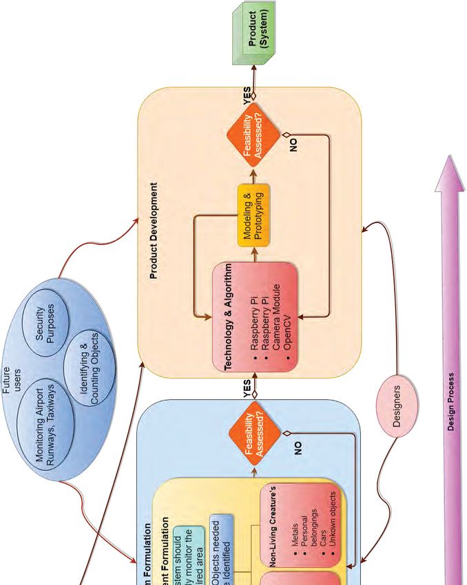
This thesis is submitted to the Department of Mathematics and Nature Science at Blekinge
Institute of Technology in partial fulfillment of the requirements for the degree of Bach-
elor in Electrical Engineering with Emphasis on Telecommunication.

Contact Information:
Authors:
Sarfaraz Ahmad Mahammad
E-mail: samh19@student.bth.se
Sushma Vendrapu
E-mail: suve19@student.bth.se

Supervisor:
Prof. Wlodek J. Kulesza

Industrial Supervisors:
Dawid Gradolewski
Damian M. Dziak
Address:
Bioseco Sp. z o. o.
Budowlanych 68 Street
80-298 Gdańsk
Poland

University Examiner:
Irina Gertsovich

Department of Mathematics and Nature Sci-     Internet   :   www.bth.se
ence
Blekinge Institute of Technology              Phone      :   +46 455 38 50 00
SE–371 79 Karlskrona, Sweden                  Fax        :   +46 455 38 50 57
Abstract

Background: The main purpose of this research is to design and develop a
cost-effective system for detection of Foreign Object Debris (FOD), dedicated
to airports. FOD detection has been a significant problem at airports as it can
cause damage to aircraft. Developing such a device to detect FOD may require
complicated hardware and software structures. The proposed solution is based on
a computer vision system, which comprises of flexible off the shelf components
such as a Raspberry Pi and Camera Module, allowing the simplistic and efficient
way to detect FOD.
Methods: The solution to this research is achieved through User-centered design,
which implies to design a system solution suitably and efficiently. The system solu-
tion specifications, objectives and limitations are derived from this User-centered
design. The possible technologies are concluded from the required functionalities
and constraints to obtain a real-time efficient FOD detection system.
Results: The results are obtained using background subtraction for FOD detection
and implementation of SSD (single-shot multi-box detector) model for FOD
classification. The performance evaluation of the system is analysed by testing the
system to detect FOD of different size for different distances. The web design is
also implemented to notify the user in real-time when there is an occurrence of
FOD.
Conclusions: We concluded that the background subtraction and SSD model
are the most suitable algorithms for the solution design with Raspberry Pi to
detect FOD in a real-time system. The system performs in real-time, giving the
efficiency of 84% for detecting medium-sized FOD such as persons at a distance
of 75 meters and 72% efficiency for detecting large-sized FOD such as cars at a
distance of 125 meters, and the average frame per second (fps) that is the system
’s performance in recording and processing frames of the area required to detect
FOD is 0.95.

Keywords: Airports, Computer vision, Performance evaluation, Real-time
systems, User Centered Design, Web design.
Acknowledgements

We would like to express our gratitude to the Bioseco Company for assigning both
of us in this project. We would like to express our gratitude to Dawid Gradolewski
and Damian Dziak. They guided us in the working process and help us with
both software and hardware problems. Thank you for giving the opportunity to
participate in such unique project.

We would also like to thank our supervisor Prof. Wlodek J. Kulesza, for pro-
viding us guidance, suggestions, and comments. He gave us inspiration and
motivation during the realization of this project.

We sincerely thank our examiner Irina Gertsovich for assigning the project.
We would also thank our parents and friends, especially to Mr. Mohammad Ali
and Mr. Ajay Kumar for helping us in this project.

This research was conducted within grant "Carrying out research and development
works necessary to develop a new autonomous AIRPORT FAUNA MONITORING
SYSTEM (AFMS) reducing the number of collisions between aircraft and birds
and mammals" (No. POIR.01.01.01-00-0020/19) from The National Centre for
Research and Development of Poland.

                                        ii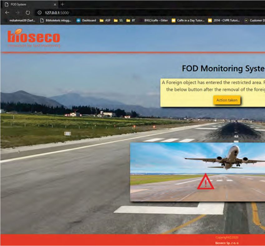
Contents

Abstract                                                                                                                                                    i

Acknowledgements                                                                                                                                           ii

List of Figures                                                                                                                                            v

List of Tables                                                                                                                                            vi

Acronyms                                                                                                                                                  vii

1 Introduction                                                                                                                                             1

2 Survey of Related Works                                                                                                                                  3
  2.1 Problem Overview .          .   .   .   .   .   .   .   .   .   .   .   .   .   .   .   .   .   .   .   .   .   .   .   .   .   .   .   .   .   .    3
  2.2 Hardware Solutions .        .   .   .   .   .   .   .   .   .   .   .   .   .   .   .   .   .   .   .   .   .   .   .   .   .   .   .   .   .   .    5
  2.3 Software Solutions .        .   .   .   .   .   .   .   .   .   .   .   .   .   .   .   .   .   .   .   .   .   .   .   .   .   .   .   .   .   .    6
  2.4 Summary . . . . . . .       .   .   .   .   .   .   .   .   .   .   .   .   .   .   .   .   .   .   .   .   .   .   .   .   .   .   .   .   .   .    7

3 Problem Statement, Objectives and Main Contributions                                                                                                     8
  3.1 Problem Statement . . . . . . . . . . . . . . . . . . . . . . . . . . . . . . .                                                                      8
  3.2 Thesis Objectives . . . . . . . . . . . . . . . . . . . . . . . . . . . . . . . .                                                                    9
  3.3 Main Contributions . . . . . . . . . . . . . . . . . . . . . . . . . . . . . . .                                                                     9

4 System Design and Modeling                                                                                                                              11
  4.1 System Design . . . . . . .             .   .   .   .   .   .   .   .   .   .   .   .   .   .   .   .   .   .   .   .   .   .   .   .   .   .   .   11
  4.2 System Modeling . . . . .               .   .   .   .   .   .   .   .   .   .   .   .   .   .   .   .   .   .   .   .   .   .   .   .   .   .   .   16
       4.2.1 Hardware Model .                 .   .   .   .   .   .   .   .   .   .   .   .   .   .   .   .   .   .   .   .   .   .   .   .   .   .   .   16
       4.2.2 Software Model . .               .   .   .   .   .   .   .   .   .   .   .   .   .   .   .   .   .   .   .   .   .   .   .   .   .   .   .   17

5 System Implementation, Prototyping and Validation                                                                                                       19
  5.1 System Implementation and Prototyping . . . . . .                                                   .   .   .   .   .   .   .   .   .   .   .   .   19
       5.1.1 Hardware Implementation and Prototype .                                                      .   .   .   .   .   .   .   .   .   .   .   .   19
       5.1.2 Software Implementation and Prototype .                                                      .   .   .   .   .   .   .   .   .   .   .   .   22
  5.2 Validation . . . . . . . . . . . . . . . . . . . . . . . . .                                        .   .   .   .   .   .   .   .   .   .   .   .   30

                                                          iii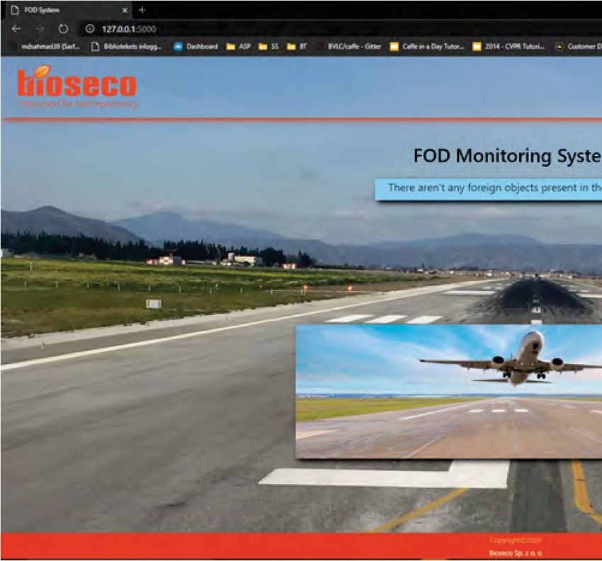
6 Discussion                                                                             36

7 Conclusions and Future Works                                                            40
  7.1 Conclusions . . . . . . . . . . . . . . . . . . . . . . . . . . . . . . . . . . . . 40
  7.2 Future Works . . . . . . . . . . . . . . . . . . . . . . . . . . . . . . . . . . . 41

References                                                                               43

Appendices                                                                               48

Appendix A                                                                   49
  A.1 Program Listing of FOD Detection and Classification . . . . . . . . . . 49

Appendix B                                                                      54
  B.1 Program Listing of Flask based Web Server . . . . . . . . . . . . . . . . 54
  B.2 Program Listing of Web Pages displayed by Web Server . . . . . . . . . 56

                                             iv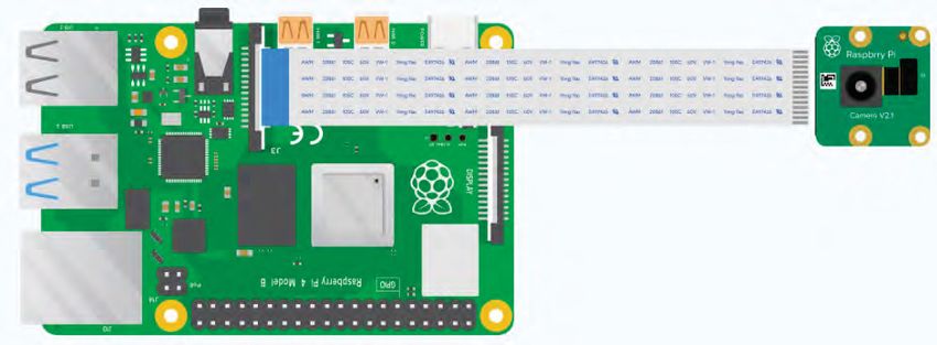
List of Figures
4.1 Proposed design process for FOD detection system . . . . . . . . . . . . 12
4.2 Block diagram of FOD detection system model . . . . . . . . . . . . . . 17
4.3 Software modeling of the FOD detection system . . . . . . . . . . . . . 18
5.1 Connection of Raspberry Pi and camera module [35] . . . . . . . . . . 20
5.2 Testing Raspberry Pi and camera module . . . . . . . . . . . . . . . . . 21
5.3 System prototype for FOD detection (front view) . . . . . . . . . . . . 21
5.4 System prototype for FOD detection (back view) . . . . . . . . . . . . . 21
5.5 System flowchart of detecting, classifing and notifying the presence
of FOD . . . . . . . . . . . . . . . . . . . . . . . . . . . . . . . . . . . . . . . 23
5.6 Flowchart for background subtraction on the system to detect FOD . 24
5.7 Flowchart of FOD classification on the system . . . . . . . . . . . . . . 27
5.8 Flowchart of web interface on the system . . . . . . . . . . . . . . . . . 28
5.9 Web interface display during no FOD occurrence . . . . . . . . . . . . . 29
5.10 Web interface response during FOD occurrence . . . . . . . . . . . . . . 29
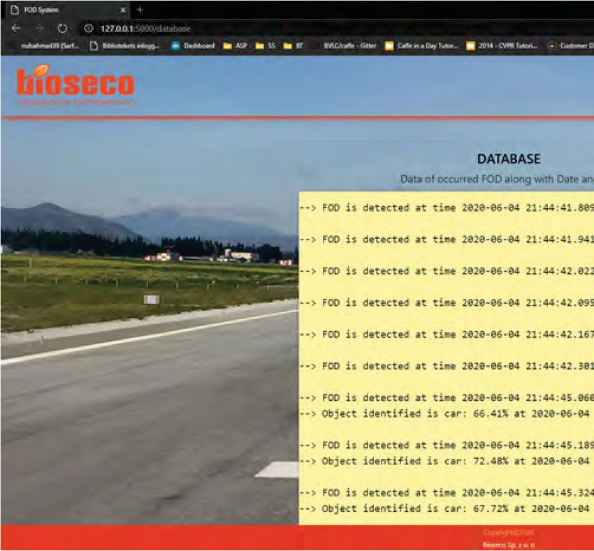
5.11 Web page displaying the data of occurred FOD . . . . . . . . . . . . . . 30
5.12 Detection of FOD (person) at a distance of 25 meters . . . . . . . . . . 32
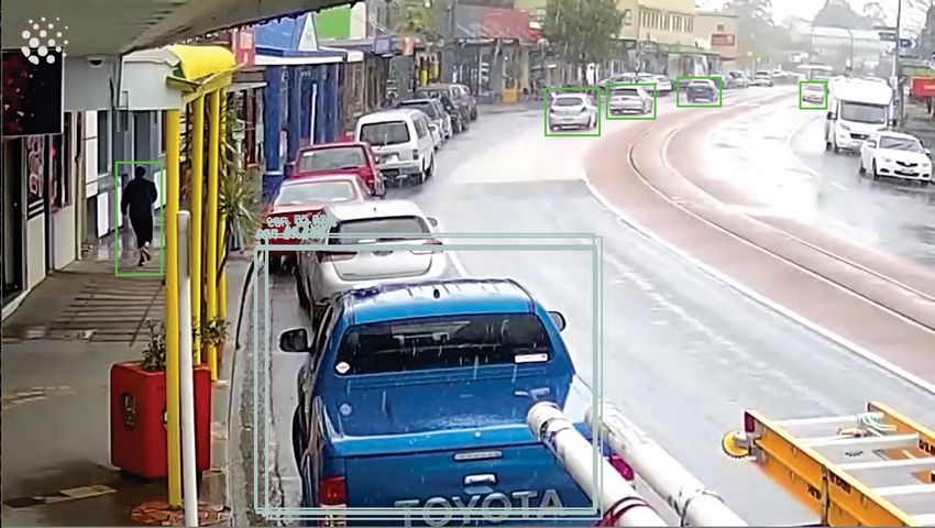
5.13 Detection and classification of multiple moving objects . . . . . . . . . 34
6.1 Graphical representation of system efficiency for detecting and clas-
sifying medium size FOD - a person . . . . . . . . . . . . . . . . . . . . . 38
6.2 Graphical representation of system efficiency for detecting and clas-
sifying large size FOD - a car . . . . . . . . . . . . . . . . . . . . . . . . . 39
v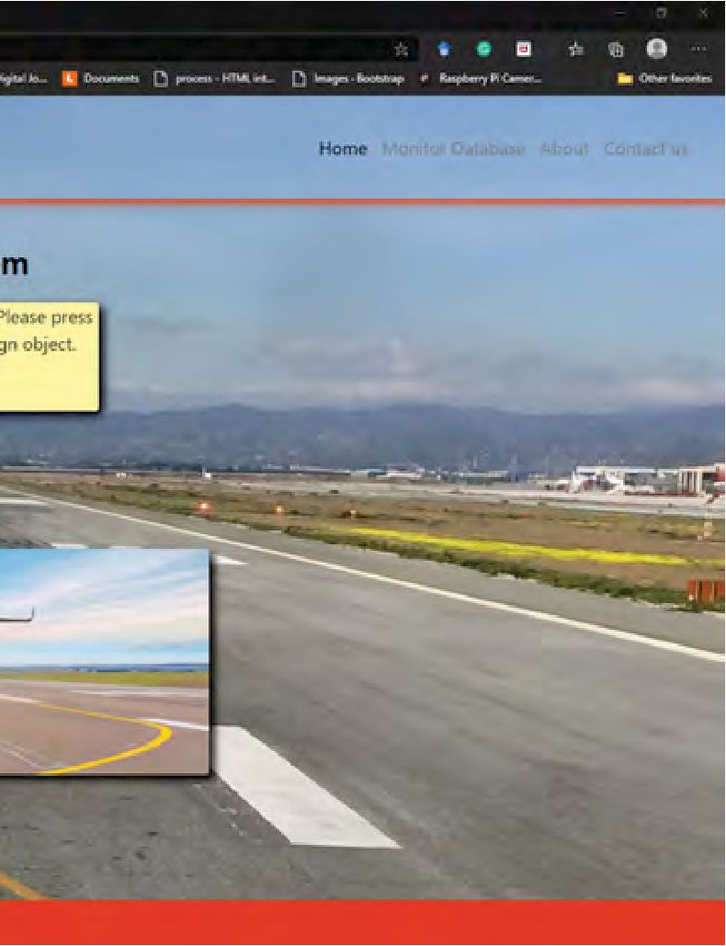
List of Tables

2.1 Sources, types of FOD and causes of occurrence [14] . . . . . . . . . .          4
2.2 State-of-the art technologies & research works . . . . . . . . . . . . . .       7

4.1 Technologies and algorithms related to itemized functionalities and
    constraints (selected technologies are bolded) . . . . . . . . . . . . . . 15

5.1   Detection and classification of FOD (person) for different distances        .   33
5.2   System efficiency for FOD (person) detection . . . . . . . . . . . . . .    .   33
5.3   System efficiency to classify the detected FOD (person) . . . . . . . .     .   34
5.4   Detection and classification of FOD (car) for different distances . .       .   35
5.5   System efficiency for FOD (car) detection . . . . . . . . . . . . . . . .   .   35

6.1 System efficiency to detect FOD . . . . . . . . . . . . . . . . . . . . . . . 37

7.1 Efficiency of the system to detect FOD for different ranges . . . . . . . 41

                                       vi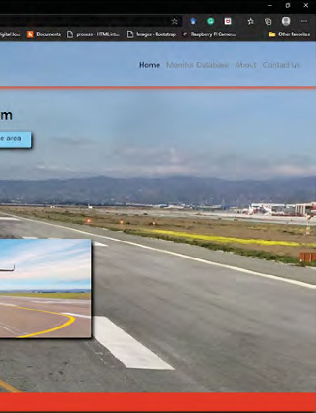
Acronyms

CNN Convolutional Neural Network.

CSS Cascading Style Sheets.

DNN Deep Neural Network.

FAA Federal Aviation Administration.

FFC Flexible Flat Cables.

FOD Foreign Object Debris.

FoV Field of View.

FPS Frame Per Second.

GPS Global Positioning System.

HTML Hyper Text Markup Language.

mAP mean Average Precision.

mmWave Millimeter Wave.

MoG Mixture-of-Gaussians.

RPN Region Proposal Networks.

SA Surface Area.

SSD Single Shot Detector.

STN Spatial Transformer Network.

UDD User-Driven Design.

WPT Wireless Power Transmission.

                                       vii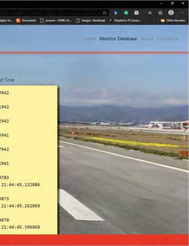
Chapter 1
                                                             Introduction

The problem with Foreign Object Debris (FOD) at the airports has increased rapidly
in recent years. It is observed that accidents due to FOD occur mainly at airport
runways, gateways and taxiways [1]. In unlikely situations, it can cause damage to
the aircraft tires or engines excluding them from operating. The resulting situation
also gives rise to the substantial delay of multiple aircraft and in extreme cases, it
can cause an accident with the possibility of casualties. Based on the research done
by the French Study on Automatic Detection Systems, over 60 % of the collection
known FOD items were made of metal, followed by 18 % made of rubber [2].

That is to say, FOD arises to a big problem in the aviation industry that im-
pacts the security of aircraft. For this reason, in recent years, several research
works were performed to develop a suitable solution for FOD detection. The
financial loss to the aviation industry is estimated to be 4 billion dollars per year
[3]. Besides the money, there are also invaluable losses, like in the year 2000
where Air France flight 4590 was crashed due to a small metal strip resulting in
in-flight fire and loss of control. The metal strip was caused by the continental
flight, which took off from the same runway moments ago. Unfortunately, this
crash resulted in 113 casualties [4].

The detection of birds and other animals at the airport runways is challenging, due
to the necessity of monitoring the vast area around the runway. Damage of aircraft
is mostly caused by bird ingestion into engines. Along with the birds many kinds
of mammals also result in damaging the aircraft due to improper security fencing
of airports. Unfortunately during one incident, a deer resulted in crashing of an
aircraft at Sitka’s runways [5], and in 2015 a kangaroo caused an aircraft crash [6].

In many airports, wildlife collisions with aircraft are on the rise. According
to the Federal Aviation Administration (FAA), the overall number of strikes raised
from about 1,800 in 1990 to over 16,000 in 2018 [7]. Further, with the rising
frequency of wildlife impacts, more focus has been given to wildlife vulnerability
analysis and the maintenance of airfield biodiversity [8]. Therefore, the mainte-
nance of runway plays an essential role in the safety of the aircraft.

                                          1
Chapter 1. Introduction 2 This project aims is to design and develop a vision-based FOD detection sys- tem that can monitor airport runways as well as taxiways and apron areas. It is important to choose a suitable algorithm and a flexible cost-efficient device with a good performance. To develop an optimal solution, we used the User-driven design (UDD) approach. The system is implemented based on the requirements of stakeholders and also future users. For FOD detection, we require algorithms and technologies with high-reliability, which are finalised after analysing the functionalities table. This paper primarily focuses on the implementation of cost-efficient FOD detection and classification system. This thesis is structured as follows: Chapter 2 gives a general overview of the most recent research work regarding the FOD detection and its taxonomy. The third chapter shows the problem statement of presented research as well as its objectives and contributions. The fourth chapter is about system design and modeling using User-driven design methodology. In the fifth chapter, a system prototype and the real world tests and evaluation are presented. The sixth chapter consists of discussion about obtained results and its outcome. The seventh chapter is about the conclusion and future works of the proposed solution.
Chapter 2
                                      Survey of Related Works

In today’s world, almost everything is being controlled and monitored by the
latest technologies. The need for FOD detection was observed not only at
airports [9] but among the others at railway tracks [10], ports [11] etc. The
FOD detection systems are not only used for detecting threat objects but also for
many other applications such as in Wireless Power Transfer system (WPT) [12]
or chest X-rays [13]. In WPT, when there is a presence of FOD in between the
transmitter coil and receiver coil, it can cause a fire accident for which FOD
detection system is necessary. The existence of FOD, such as buttons on cloth-
ing, can reduce the performance of chest X-rays for identifying pulmonary diseases.

This chapter gives general overview of technologies and algorithms, that can
be used for FOD detection at airports. This chapter is divided into two sections,
the overview and the research works. The overview part consists of the research
of statistical analysis of FOD, which relates to the origin of different kinds of FOD
with its resulting damage for different circumstances. Research works cover the
study of compositions of different technologies, their architecture hierarchy and
their final results to overcome the problem of FOD.

2.1     Problem Overview
FOD can result from many circumstances, and it can consist of any substance
(living or non-living) as well as it can be of any dimensions (can be measured as
area enclosing the FOD in m2 ). The FOD may be divided in many ways regarding
its type and origin [14]. The Nature, Technology and Human are the most common
reasons for FOD occurrence. Table 2.1 shortly summarizes the sources of FOD,
their types and the causes.

The main complications, which may occur due to FOD, concerning aircraft
or airport management are damaging the engine due to ingestion of FOD, ruining
the tyre as well as damaging the structure of aircraft and reducing its performance.
Moreover, these incidents may drive to disrupting the normal functioning of the
airport resulting in revenue loss. These complications are explained briefly further.

                                         3
Chapter 2. Survey of Related Works 4
Table 2.1: Sources, types of FOD and causes of occurrence [14]
Source Type Causes of occurrence
Animals - due to improper
Wildlife, Plant fragments, security fence.
Nature Broken branches, Stones, Avi fauna - through the air.
Snow, Ice. Miscellaneous objects - due
to wind.
- Due to shattering of loose
parts of aircraft while
Technological Fuel caps, Landing gear
takeoff or landing.
artefacts fitting, Nuts, Metal sheets.
- Due to wind depositing
the objects.
Mechanics tools, - Due to authorities careless-
Catering supplies & ness during a regular
Human
their debris, Personel inspection of runways.
artefacts
badges, Maintenance & - Due to wind depositing
construction equipment apron items.
Engines are highly susceptible to objects of any kind (either soft or hard and
irrespective of size and shape). Once they strike the working engine, they can
damage the rotating blades, static vanes or other parts of the engine. Rotatory
blades can be easily bent by such objects, which results in lower efficiency perfor-
mance of the engine. In rare instances, they can damage the whole structure of
the engine [15] leading to the aeroplane crashes. One of the incidents is Miracle
on the Hudson in 2009, in which Airbus A320-214 lost thrust on both engines due
to ingestion of large birds into engines after immediate takeoff [16]. The aircraft
was landed on the Hudson river safely with no fatalities.
Another example is tyre damages. In some cases, FOD can result in detach-
ment of tyre treads, which can cause damage to other parts of aircraft or even
cause difficulties to the other aircraft, which are going to take off or land on
the same runway. There are certain instances where the FOD object can be fully
penetrated inside the aircraft tyre and be undetectable during the inspection. Such
cases can result in tyre bursts and cause huge loss [15]. Example of this was a
43-inch metal strip left on the runway infiltrated into the aircraft tyre in Concorde
crash in 2000. The metal piece caused tyre-burst, which in turn ruptured fuel tank
resulting in a plane crash with 113 fatalities [17].
The areas such as fuselage (aircraft’s main body section), wings, nose, the
windshield can also be damaged by FOD. The damage to the aircraft’s structureChapter 2. Survey of Related Works 5 results in an aerodynamic loss. If the aircraft nose gets damaged due to FOD, it could corrupt the aircraft’s radar system, which then gives faulty readings resulting in more complicated things [15]. Another undesirable result of FOD is the disruption of the normal function- ing of the airport. Moreover, when the aircraft gets damaged due to FOD on the runways, it causes flight delays, cancellation of flights and revenue loss. Due to such cases, additional works by employees is also required [15]. There has been a lot of research works focusing on the development of a suitable FOD detection system. The crucial part of each detection system is the algorithm and its implementation in real-time. The results obtained from the research work by choosing the desired algorithm is also explained briefly. The Bioseco company of Poland [18] is also working on the research and development that is necessary to develop a new autonomous AIRPORT FAUNA MONITORING SYSTEM (AFMS) reducing the number of collisions between aircraft and birds and mammals. This project aims to conduct research and development efforts, which will allow the development of a prototype of the new AIRPORT FAUNA MONITORING SYSTEM [19]. 2.2 Hardware Solutions This section contains solutions depending upon hardware components or sensors to detect FOD. These solutions can be obtained using radar technologies and lidar technologies. Explicit modeling and installation of the system are necessary for detecting FOD. Maintenance of the sensors is also required for the effectiveness of the system. FOD detection can be achieved using radar technology. One such research work is Millimeter-wave Ground-based Synthetic Aperture Radar Imaging for Foreign Object Debris Detection. In this research work, the ground-based synthetic aperture radar (GB-SAR) technique is used to study millimeter-wave imaging of FOD present on the ground. The experiments performed for detecting FOD such as braces and screws using millimeter wave frequency bands from 32 GHz to 36 GHz and from 90 GHz to 95 GHz. In addition to this, matched-filter algorithm is performed to reconstruct the image with proper system parameters and to comprehend the factors affecting the system for successful detection of FOD. The system can successfully detect the screws at a distance of 2 meters along with FOD size (40 mm L × 12 mm W). However, modifications are needed for detecting FOD at a long distance [20]. There are several other research works such as millimeter-wave radar for foreign objects debris detection on airport runways [21], millimeter-wave imaging of foreign object debris (FOD) based on
Chapter 2. Survey of Related Works                                                6

a two-dimensional approach [22]. But installing such systems requires additional
permission from airport management as it can be interrupted with signals of
aircraft. Implementation and maintenance of the system is expensive, which
makes this system hard to install at small and medium-sized airports.

2.3     Software Solutions
This section contains solutions depending upon software programs to detect FOD.
The working of these programs also depends on the system capabilities to run the
program effectively. Most of these solutions require a camera module to take input
of required area and identify the presence of FOD.

In Video-based Foreign Object Debris detection [23], [24], the algorithm compares
the images taken at different times to identify if any FOD has entered the region.
Several cameras are fixed alongside the runway, which captures images at real-
time. These images are then performed with multiple image processing techniques
such as image pre-processing for intensity normalization of the captured image to
filter out the unwanted changes, which may occur due to camera instability. As
the airport runway is the static scene, a constant background is subtracted from
the current captured frame. Finally, image post-processing, which includes noise
removal based on mean filtering algorithm and the morphological operation to
fill in the holes. Although the FOD detection system can detect the FOD of size
4 cm, a large number of cameras are required to cover the whole runway. As the
cameras are installed very close to the runway, the detection range is very small,
which lacks the foremost required objective of FOD detection system.

The Region-Based CNN for Foreign Object Debris Detection on Airfield Pavement
[25] comprises of a vehicle on which four GT2050C cameras with 2048 pix-
els (px) × 2048 px resolution, scanning for 5 meters in width at the same time
are mounted. The GPS of the moving vehicle is utilised to identify the location of
detected FOD. The detection of FOD is achieved by implementing the Convolution
Neural Network (CNN). This CNN classifier contains two modules, Region Proposal
Network (RPN) and Spatial Transformer Network (STN). Identifying FOD is done
in two stages. In the first stage, the RPN is implemented by a dataset containing
(2048 px × 2048 px) sampled size images of 3562 screws and 4202 stones. In the
second stage, the STN is implemented to adjust the targets from the influence of
scale, rotation and warping. Then adjusted images are analysed with CNN classifier
to identify FOD. The proposed algorithm is implemented on a GTX 1080ti GPU,
achieving 26 fps real-time sampling frequency to detect screws and stones with
an accuracy of 97.67%. Employing such high computational algorithm is slightly
challenging as well as using a vehicle to detect FOD requires additional permissions
from airport management.
Chapter 2. Survey of Related Works                                                  7

There are certain research works, which are implemented to detect objects
in a general case scenario. One of the research work is Multiple Object Detection
using OpenCV on an Embedded Platform. The embedded platform used here is
Texas Instrument DM3730 digital media processor, and the algorithm is based on
cascade classifier. The dataset, which is used to train cascade classifier consists of
4000 positive images of dog, hand signs, plastic bottle, face etc. Finally, an XML file
is generated, which contains data for the object to be detected. Implementation
of the object detection algorithm was performed using C++ language in the
OpenCV library, and the compilation was accomplished using GCC (GNU Compiler
Collection). The execution time of cascade classifier for single object detection is
95 ms. However, this research work lacks the size of the object detected and the
distance between the installed system and the object detected [26].

2.4     Summary
All the FOD detection systems can be classified depending on used technologies on
two main classes, vision and radar technologies. The summary of research study is
presented in Table 2.2.

             Table 2.2: State-of-the art technologies & research works

       Technology                             Research Works
      Radar systems                Millimeter Wave (mmWave) [20]–[22].
                                        Motion detection [23], [24].
      Vision systems                      AI based solutions [25].
                                           Object detection [26].
Chapter 3
Problem Statement, Objectives and Main
Contributions
This chapter is dedicated to present the methodological approach of the thesis in-
cluding Problem Statement, Thesis Objectives and Main Contributions. Problem
statement section presents the complexity of composing a fit solution to overcome
the problem of FOD. Thesis objectives section contains the objectives, which are
required to design and develop a suitable solution for the system. Main contribu-
tions section contains the individual contributions of both the authors regarding
the designing and development of the system and report writing.
3.1 Problem Statement
The monitoring of airport runways is very challenging as FOD can be of any
size. The system must perform FOD detection with high accuracy (efficiency to
detect the presence of FOD), should work remotely, and it should cover the whole
required detection area to ensure the safety of aircraft. The system must tackle the
problem of detecting FOD even at a far distance, and the classification of the FOD
is also necessary.
To achieve a best-fit solution to the problem of FOD detection, we perform a
detailed study of related work, concerning vision-based FOD systems and radar
technology. Many technologies have been implemented and tested at airports to
provide an efficient solution. However, radar-based solutions require expensive
sensors and additional permission, hence they are not available for small and
medium-size airports. The vision-based solution is possible, however, it requires
high computational capabilities of CPU/GPU and dedicated software. Instead of
using high, expensive technologies, which required high computational power and
complicated hardware structures, we wish to use techniques of image processing
using computer vision. The thesis problem that we deal with is to propose a
flexible cost-effective solution using off-the-shelf components allowing the FOD
detection and classification in real-time.
8Chapter 3. Problem Statement, Objectives and Main Contributions 9 3.2 Thesis Objectives The first objective of this thesis is to compose a User-Driven Design (UDD) to define the ultimate requirements of the FOD detection system and constraints concerning the development of the system, which are necessitated for the system solution to overcome the problem of FOD. The second objective is to establish a unique design for the development of a FOD detection system analysing all the possible technologies and algorithms. The system should be composed of economically available hardware components. Such devices may contain low computational power for which the implementation of the chosen algorithm must be done very meticulously. After determining the suitable technologies and algorithms, the feasibility of the system is assessed to achieve a fit solution. The third objective is to implement and prototype the FOD detection system. The system should be installed at the desired location to evaluate the achievable ultimate goals of FOD detection system in the real-world. The system should be examined for detecting FOD of different sizes and for different distances. The outcomes of this evaluation defines the efficiency of the system. 3.3 Main Contributions In this thesis, the fit solution design for implementing a FOD detection system dedicated to airports is achieved. Various possible technologies and algorithms are scrutinised and tested in real-world for achieving a proper solution for this system. The accomplishment of the requirements, objectives and performance of the system are examined after analysing the outcomes. The technologies and algorithms, which are capable of solving the problem of FOD are finalised for evaluation. A web interface is also created to notify the user in real-time when there is a FOD occurrence. The division of work is satisfied with the weekly project updates to the su- pervisor. Mr Sarfaraz Ahmad Mahammad (Author1) performed the system design while Ms Sushma Vendrapu (Author2) has evaluated and revised the design process to acquire a more suitable and efficient FOD detection system. Author2 collected and modified the data, Author1 performed the training process of the FOD classification network. Author1 designed the web interface and prepared prototype of the FOD detection system for evaluating the system in real-world. Both Author1 and Author2 have conducted the implementation and testing of the system. In the report, Author1 wrote the Chapter 2, Chapter 4, Chapter 5 and Author2 modified those chapters again. While Author2 wrote the Chapter 1,
Chapter 3. Problem Statement, Objectives and Main Contributions          10

Chapter 6, Chapter 7 and Author1 modified those chapters again. Chapter 3 was
written and modified by both Author1 and Author2.
Chapter 4
                             System Design and Modeling

This chapters aims to show design process along with its outcome in terms of system
model, for which this chapter is divided into two sections such as System Design,
which consists of designing of FOD detection system using UDD and System Model-
ing, which represents aspects of FOD detection system for the development process.

4.1     System Design
Figure 4.1 presents the UDD, which helps to understand the requirements and
preferences of stakeholders and future users in terms of system features, tasks
and objectives [27]. The constructed UDD consists of requirement formulation in
which the system solution specifications, objectives and limitations are formulated
to overcome the problem of FOD and product development, which consists of
suitable technologies and algorithms, utilised to design and develop the system for
FOD detection in real-time.

While designing a system, limitations play a crucial role in defining efficiency. The
main objective of the system is to monitor the runway constantly for the occurrence
of FOD. As mentioned in the overview section of Chapter 2, FOD is of many types.
For a feasible understanding, they can be divided into two types, such as living
creatures and non-living creatures. The living creatures include birds, humans and
mammals whereas non-living creatures include metals, personal belongings, cars
and unknown objects such as broken parts of technology artifacts.

There are many technologies, which can be employed to detect FOD at air-
ports. But as mentioned in the research works section of Chapter 2, they all
comprise of high-cost and complicated technology, which requires maintenance.
The problem of detecting the FOD is very challenging as they can be of any size.
Precise requirements of both hardware and software technology are essential for
the effective performance of the system. However, the main aim of this project is
to provide a solution for cost-effective and simplistic model for detection of FOD.
Therefore, Raspberry Pi and a camera module are utilised to develop the system.

                                        11
Chapter 4. System Design and Modeling 12
Figure 4.1: Proposed design process for FOD detection systemChapter 4. System Design and Modeling 13 The feasibility of the system is evaluated for specified objectives and require- ments given by the users and the stakeholders. The users must also examine whether the currently available desirable solutions are capable of solving the problems addressed and whether the requirements are achievable or not. If there is a problem in achieving the prerequisites, the company stakeholders and end-users would demand to change the requirements in such a way to appease them. After an assessment, all the specified requirements can be accomplished, and product development can be established. Generally, because of the assertion in trade-offs and variance of the required components and prerequisites, the selection of feasible technologies and methods such as algorithms must be borne deliberately in the consecutive steps: 1. Selection of technologies and algorithms, 2. Prototyping and modeling, 3. Validation of the solution. Additionally, during the development phase of the system, the stakeholders and future-users are concerned, although it is the designer’s responsibility to drive the discussion between the contributors. The primary duty of the end-users and company stakeholders during the product development is to monitor if all the prerequisites and specified requirements are accomplished. After the validation of the components and limitations, the possible required developments can be asserted. We have to carefully select technologies and algorithms considering the stake- holder’s problems and requirements. The suitable algorithms and techniques are taken by determining the issue of FOD at runways considering with far distance. The preferred technologies and tools must signify the price compatible after the algorithms are chosen for the particular device. There are various algorithms, through which the problem of FOD can be solved. However, users can be involved in the selection process for attaining different types of prerequisites with a different perception. The modeling of the system depends on the provided requirements and de- sign process describing the way users want it to be. Moreover, it represents both hardware and software development processes precisely along with flowcharts of algorithms from the working technologies, functionalities, and constraints. Prototyping of the system shows the actual detection process and its outcomes for the given requirements. Using such a computer vision process, the system depends on software and hardware analysis, capturing the FOD in real-time and displaying the data in the web interface.
Chapter 4. System Design and Modeling                                             14

The validation and evaluation shows the system capabilities. The stakehold-
ers can check the exact outcome of the proposed requirements and technologies.
If the results are the same as expected from the design process, the system is
finalised and modified for additional objectives. Otherwise the designing process
is repeated for attaining the requirements. The validation presents the complete
evaluation part of the hardware and software system.

Technologies and algorithms related to itemized functionalities and constraints are
presented in Table 4.1. The table consists of three sections such as functionalities,
constraints and possible technologies. The functionalities are further divided into
general and itemized. The general functionalities define the characteristics of the
required functionality, whereas itemized specifies particular measures required
to measure the functionality. Constraints depict the different items, through
which the itemized functionality is determined and measured. Technologies
and algorithms states, which solutions are suitable for a particular functionality.
The selected technologies and algorithms for modeling the system from possible
technologies and algorithms are bolded.

The main functionality of the system solution is the detection of FOD, which
can be itemized as monitoring runways. The constraints defining this functionality
is detecting moving and non-moving objects. The reliability of the system must
be more than 95% and should perform in real-time with a performance of more
than 0.5 fps. The plausible technologies and algorithms for both hardware and
software are radar technology, beam patterns, CNN, RPN, computer vision process,
electro-coupled devices, deep neural network.

The system solution also requires the functionality of classification of the de-
tected FOD. The objects required for classification can be divided into two groups
for easy understanding of users such as wildlife and other objects. The wildlife
category can be further divided into constraints such as the small-sized objects
with surface area (SA) more than 0.98 m2 like dogs, fox, sheep etc. And large size
objects with SA higher than 1.9 m2 such as deer, moose etc. Other miscellaneous
objects, which include broken parts of metal or plastic and so on. Where small
miscellaneous objects with surface area (SA) should be more than 0.89 m2 such
as metals, plastics etc. And large miscellaneous objects with SA must be greater
than 5.6 m2 such as cars etc. The FOD classification can be obtained by using
technologies and algorithms like vision system, hog, YOLO, MobileNet, SSD,
R-CNN, haar-cascade, radar, lidar and beam patterns.

Detection feasibility specifies the algorithm performance functionalities ac-
cording to the detection process. For the system to successfully detect the FOD,
the object size must be greater than 0.5 m2 , the frame rate achievable is less
Chapter 4. System Design and Modeling                                            15

Table 4.1: Technologies and algorithms related to itemized functionalities and con-
straints (selected technologies are bolded)

                                                           Possible technologies
          Functionalities                Constraints
                                                              and algorithms
     General          Itemized
                                          Moving and
                                                           Radar technology, Beam
                                          non-moving
                                                             Patterns, CNN, RPN,
                     Monitoring              objects,
    Detection                                                 Computer vision,
                      runways         Reliability > 95%,
                                                           Electro-coupled devices,
                                           Real-time
                                                           Deep Neural Network
                                         performance.
                                              Small-
                                           object size
                                       (SA) > 0.98 m2       Vision system, Hog,
                                            eg. dogs.        YOLO, MobileNet,
                       Wildlife
                                              Large-            SSD, R-CNN,
                                           object size         Haar-Cascade
     Object
                                        (SA) > 1.9 m2
  classification
                                            eg. deer.
                                              Small-
                                           object size
                                       (SA) > 0.01 m2        Radar technology,
                                          eg. metals.        Lidar technology,
                    Other objects
                                              Large-         Computer vision,
                                           object size        Beam patterns
                                        (SA) > 5.6 m2
                                            eg. cars.
                                              Object-
                                                             R-CNN, Background
                                        size > 0.5 m2 ,
    Detection        Algorithm                             subtraction, Computer
                                             fps < 1,
    feasibility     performance                            vision, Neural Network,
                                           Detection-
                                                            Deep Learning, YOLO
                                       range < 250 m
                                                               GSM, Wi-Fi,
                                        Secure, High            Bluetooth,
 Communication     Threat apprise
                                         reliability          Web interface,
                                                                Ethernet.
                                                           Embedded platforms,
                      Reliability,
                                                                Antennas,
     System          Performance        Power supply,
                                                             Camera Module,
  specifications     Cost-effective-    Apt to territory.
                                                               IR sensors,
                         ness
                                                               Ultrasound.
Chapter 4. System Design and Modeling 16 than the 1 fps, and detection-range should be up-to 250 m2 . These constraints can be obtained by using these possible technologies and algorithms like R-CNN, background subtraction, computer vision, neural networks, deep learning, YOLO. As the system will be installed in a remote location, the communication part is essential. The FOD detection system shows the status of detected FOD in the web interface, which covers the functionality of the communication section. It is itemized as a threat apprise, and the constraints required are secure and highly reliable in real-time as the system should be efficient for the safety of the aircraft. The possible technologies and algorithms are GSM, wi-fi, bluetooth, web interface and ethernet. The system specifications are itemized for selecting the proper hardware technology for the implementation of the detection system. The device must be reliable, cost-efficient and with good performance for the prototyping vision system. The constraints, which affect the system specifications are the power supply and suitable region or area where the system will be installed. 4.2 System Modeling This section is defined in two sub-sections such as Hardware Model and Software Model. Hardware Model section contains the required aspects of hardware com- ponents for the development of the system. Software Model section contains the functioning requirements of the algorithm for detecting the FOD. 4.2.1 Hardware Model As the second objective stated, the hardware components utilised for the develop- ment of the system must be economically available. The system should also work remotely with standard power supply, for which a standard and suitable embedded system must be appropriated for the development of the system. As the system is designed to work on the vision system, a camera module is also required. The required monitoring area, which is the airport runway is considerably large. So, a proper lens should also be utilised with camera module for precise monitoring of the area. The block diagram presenting the general aspects of the FOD detection sys- tem model is shown in Figure 4.2. The selected technology, which is an embedded system is connected to the power supply and camera module. It should also be connected with either Wi-Fi or Ethernet for uploading the FOD detection results, as the system is working remotely. The algorithm must be uploaded to this embedded
Chapter 4. System Design and Modeling                                           17

system for detection of FOD. And finally, the results from this algorithm are passed
to the web interface for alerting the user.

            Figure 4.2: Block diagram of FOD detection system model

4.2.2    Software Model
As the airport runway is a static place where there is considered to be no movement
of unnecessary objects, for such places constant frame by frame monitoring is fit.
Subtraction of the foreground from the background is a significant pre-processing
stage in many vision-based applications. Although there are several background
subtraction techniques, which can be achieved using computer vision, proper
selection is essential to satisfy every aspect in monitoring the airport such as
lighting conditions, required monitoring area, size of the object to detect and
performance.

With the help of the OpenCV library, we can analyze the image and perform
different image processing techniques for our required prerequisites. As well as
using this library, we can load trained models such as haar-cascade model [28],
SSD model [29], YOLO model [30] etc for object classification. But such object
classification models require devices with high computational power. The selection
Chapter 4. System Design and Modeling 18
and implementation of the object classification model must be done accordingly to
the chosen hardware components for a good result from the final FOD detection
system. The simplified flowchart of the system is shown in the Figure 4.3. The
system should first capture the video from the camera module. After capturing the
video the system should detect the presence of FOD. If FOD is detected, the system
should classify the FOD. after which the system alerts the user of FOD occurrence
Figure 4.3: Software modeling of the FOD detection systemChapter 5
System Implementation, Prototyping and
Validation
This chapter presents the principle of system implementation, its prototype and val-
idation scenarios. Implementation and Prototyping section describe the develop-
ment and installation of the system in real-world at the desired location for testing
the efficiency of the outcomes. Validation section contains the results obtained after
prototyping of the system.
5.1 System Implementation and Prototyping
This section contains the Implementation and Prototyping of the whole system and
is represented as Hardware Implementation and Prototyping, which is selections
of components, connections and installation of the system at the desired location
for FOD detection. This section also contains Software Implementation and Proto-
typing, which is the implementation of coding part with selected technologies and
algorithms for FOD detection system as well as web interface to notify the user.
5.1.1 Hardware Implementation and Prototype
The components required for implementation of this system are Raspberry Pi 3
Model B+ and a Sony IMX219 camera module. As mentioned in the first objective,
the system requires to work remotely, and it should be able to work with the desired
chosen algorithm for object detection efficiently. Raspberry Pi 3 Model B+, which is
a single-board computer suffices for designing our system as it allows for rapid pro-
totyping of vision based algorithms. It is frequently used in research projects. The
single-board computer Raspberry Pi has been standard, low in cost, compact design
and wireless connectivity. It contains Broadcom BCM2837B0, Cortex-A53 (ARMv8)
64-bit SoC and 1 GB LPDDR2 SDRAM, which is satisfactory to perform our selected
algorithms. It also accommodates 2.4 GHz and 5 GHz IEEE 802.11.b/g/n/ac wire-
less LAN to upload the values to the web interface from time to time. The selected
camera module will be connected to CSI camera port of Raspberry Pi 3 Model B+
[31].
19Chapter 5. System Implementation, Prototyping and Validation 20
For selecting the camera module, the factors considered are focal length and reso-
lution. As the system should also be able to classify the detected objects, these two
factors are significant.
Focal Leng th × FoV = h × W or king Dist ance and (5.1)
1
Focal Leng th ∝ (5.2)
FoV
Equation 5.1 can be found in [32], where h is the horizontal sensor dimension
(horizontal pixel count, multiplied by pixel size). As mentioned in Equation (5.2),
with the increase in the focal length the Field of View (FoV) decreases, which results
in an increase of object size in pixels [33]. The selected camera module is Sony
IMX219, which consists of focal length 25 mm along with a CS-mount lens, which
also allows the system to detect the moment of the objects around the runway as
well with a field of view of 16°. The selected camera, which is CMOS 8-megapixel
colour camera can record videos with a resolution of 1080 px along with a speed
of 30 fps [34]. The camera module should be connected to Raspberry Pi using the
standard 15 pin to 15 pin Pi camera cable (FFC) [35], as shown in Figure 5.1.
Figure 5.1: Connection of Raspberry Pi and camera module [35]
Before prototyping the system the connections between selected technologies are
tested, which is shown in Figure 5.2. Raspberry Pi 3 Model B+ is connected with
Sony IMX219 camera module with the standard 15-pin to 15-pin Pi camera cable
(FFC). The camera is fixed firmly over a supportive card-board structure for testing
purpose, and the Raspberry Pi is located below the camera module, which is shown
in Figure 5.3 and Figure 5.4. Raspberry Pi is connected to a power adapter, which
provides 5 V and 2.5 A power supply. And the Raspberry Pi is controlled using the
VNC server on a laptop remotely.Chapter 5. System Implementation, Prototyping and Validation 21
Figure 5.2: Testing Raspberry Pi and camera module
Figure 5.3: System prototype for FOD detection (front view)
Figure 5.4: System prototype for FOD detection (back view)Chapter 5. System Implementation, Prototyping and Validation 22 5.1.2 Software Implementation and Prototype The coding part of the algorithm for FOD detection as well as the classification of detected FOD is implemented in Python 3.8.0 using libraries OpenCV, Imutils, Numpy and Datetime. These libraries provide convenience functions to perform basic image processing techniques and a collection of high-level mathematical functions. For detecting the presence of FOD, background subtraction technique based on Gaussian distribution, which is BackgroundSubtractorMOG2 algorithm pro- vided by OpenCV is utilised for implementation of this system. It is an algorithm based on the Gaussian mixture applied to the background and foreground segmen- tation. Although there are many background subtraction algorithms, this algorithm is selected as it is advanced in many aspects and its performance stability, even when there are lighting contingencies. One essential aspect of this algorithm is the acquisition of the correct number of Gaussian distributions for each pixel over the entire frame. Another important aspect of this algorithm is improved identification of shadows in frames. Multiple objects can be identified, which are distinct from foreground and background [36], [37]. The classification of detected FOD is achieved by implementing the Single Shot Multi-box Detector (SSD), which performs object classification for real-time applications. As the name implies, SSD creates multiple boxes of different sizes and aspect ratios on various objects present in the input image. At the time of estimation, the network produces outcomes for each type of object in each box. Then it allows changes to the box to best suit the form of the object [29]. SSD requires just one shot to identify several items in a picture using a multi-box. SSD is considerably quicker in the processing speed and high-precision target detection algorithm. For FOD classification, SSD is chosen due to its efficient performance and speed when compared to other classification algorithms. The performance of such algorithms is analysed by mean Average Precision (mAP), which is the average precision value for recall value over 0% to 100%, where precision is the correctness of the prediction results and recall is the how significant the positive detections are obtained. When performing different detection algorithms on the VOC2007 dataset, the results are SSD achieves 77.2% mAP for the input resolution of 300 px × 300 px at 46 fps. Whereas for an input resolution of 512 px × 512 px, SSD achieves 79.8% mAP at 19 fps. Considering these results, SSD outperforms state of the art Faster R-CNN, which can achieve 73.2% at 7 fps and YOLO, which can achieve 63.4% at 4 fps [29]. When considering real-time applications as in our problem, accuracy and FPS speed, which are measures of the system performance, are vital, and for which SSD is much suitable for our objective. The entire process for the implementation of FOD detection system consists
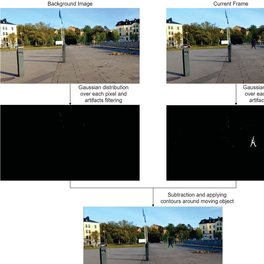
Chapter 5. System Implementation, Prototyping and Validation                    23

of three phases. In phase one, the process explains identifying a foreign object.
In phase two, the process classifies the objects recognised in the previous step.
Phase three consists of assembling a dedicated web interface. The flowchart of the
program for detecting FOD is shown in Figure 5.5.

Figure 5.5: System flowchart of detecting, classifing and notifying the presence of
FOD

The main objective of our system is to identify the presence of FOD. FOD
may include broken parts and many other anonymous objects, which cannot be
classified. The most reliable method to distinguish these FOD is by continuous
frame by frame monitoring of the region. Background subtraction algorithm based
on Gaussian distribution is highly suitable to overcome this type of problem in the
FOD detection system. The complete process of recognizing FOD using background
subtraction based on Mixture of Gaussians (MoG) algorithm is illustrated in the
Figure 5.6.

The system first captures the video. Each frame from the captured video is
passed through the background subtraction algorithm one after the other. Back-
ground subtraction algorithm takes the source pixels from the captured frame and
assigns each pixel a specified Gaussian distribution. The time for which the object
remain in the scene is the weight of this distribution. This algorithm generates
the foreground mask of the captured frame by assigning Gaussian weights to each
pixel. When the system captures another frame, this foreground mask updates
the background mask. Moreover, this process continues as the frames progressed
continuously [38].
Chapter 5. System Implementation, Prototyping and Validation                       24

 Figure 5.6: Flowchart for background subtraction on the system to detect FOD

So now, the frame contains different Gaussian values for different pixels.
This frame is thresholded such that noise is excluded, pixels with too low or too
high values are filtered out. While thresholding of the image, the same threshold
value is applied to each pixel. When the pixel value is smaller than the assigned
mark, it will be set to zero otherwise, it will be set to a maximum. Finally, a binary
image is obtained after thresholding the frame [39], [40].

The resulted image from the previous step is noise-free, now dilation of the
frame is done to fill the holes. By performing dilation to the image, it extends a
pixel neighborhood over which the source image takes the maximum value of the
element via the specified structuring element. Dilation is effective in combining
the splitting elements as we need to obtain the whole structure of moving object.
This process is performed multiple times to fill the holes accurately [41]–[43].

Consequently, after identifying the difference in binary values from background to
foreground, a bounding box should be constructed over those pixels. OpenCV’s
contours function is a useful tool to analyze shapes and detect and recognize
objects. Contours function is applied to connect the curve that connects all the
continuous points (along the boundary) with the same binary value in dilated and
thresholded binary image [44].

The final output consists of a rectangular box around the moving object present
in the frame. Thus identification of moving objects is achievable by this selected
algorithm, which results in achieving part of the first objective.

Therefore, the system can detect the presence of FOD now, the system must
be able to classify them, which is presented in phase two. Here we will be using
Caffe [45] framework, which is a deep learning framework to train a SSD model
for our required FOD classification data-set. Caffe is inscribed in C++ and has
bindings of Python and Matlab.
Chapter 5. System Implementation, Prototyping and Validation                      25

There are five steps involved in training an SSD model with Caffe framework.

   • Step 1 - Caffe framework: Installing the Caffe framework suitable for the sys-
     tem along with required dependencies. It also requires several prerequisites
     before installation. The official documentation is provided for a clean instal-
     lation of this framework by BAIR [46].

   • Step 2 - Data preparation: Now preparing the dataset for object identification.
     This step involves collecting suitable images of FOD for the dataset. After this
     process, this step requires generating lmdb files and solver definition.

   • Step 3 - Model training: This step involves fetching the lmdb files of the cus-
     tom dataset to the Caffe framework. A pretrained weight is used to train the
     model.

   • Step 4 - Model deploying: After training, the model is deployed in order to
     work with OpenCV’s deep neural network.

   • Step 5 - Implementation on Raspberry Pi: This is the most crucial part. As
     Raspberry Pi contains limited memory and processing speed, the implemen-
     tation process may affect the final performance. To improve the parallel per-
     formance of both algorithms, it is implemented on Deep Neural Network of
     OpenCV.

The above-explained steps are here further described briefly on how to train and
deploy an SSD model for FOD classification.

Stage 1: The main dependencies by which we are going to train the model
with the Caffe framework are Nvidia CUDA Toolkit and Nvidia cuDNN. These
dependencies are used to speed up the training process with more efficiency. The
installation procedure is followed by official documentation from BAIR [45].

Stage 2: The collected data-set primarily consists of animals as they pose a
huge threat to the safety of aircraft during landing or takeoff procedures. The
factors considered during the collection process are the animals that can have
access to airports due to improper security fencing such as birds and mammals,
which are abundant at various places. Some of the animals are considered based
on previously occurred events regarding FOD at airports. The birds, which are
included in the data-set to be detected by the system are:
                 • Cranes                         • Herons

                • Eagles                          • Pelicans

                • Hawks                           • Vultures
Chapter 5. System Implementation, Prototyping and Validation 26
The mammals, which can be found abundantly in some areas are included
in this data-set including the mammals, which resulted in the occurrence of
previous FOD incidents and they are:
• Alligator • Kangaroo
• Deer • Monkey
• Dogs • Moose
• Fox • Raccoon
• Horse • Sheep
The system is also capable of classifying objects such as cars and human be-
ings. The whole dataset consists of 7612 images, where each object holds at least
400 images. Now LMDB files are generated using tools provided by the framework
for our custom dataset. The LMDB file is a key-value repository database used by
the Caffe framework. Some of the most advantages of this strategy are its strong
efficiency. Training and testing datasets are translated to a form stored in the
LMDB file.
Stage 3: The model is then trained by weights evaluated by the SSD imple-
mentation in Caffe [29]. After the training process is completed, the outputs will
be the Caffe model and solver state, which are further used to deploy the model.
Stage 4: After the model is trained, it is deployed with the help of previ-
ously generated solver state files and provided pre-trained weights by which
it is trained. The DNN of OpenCV can now load this model, which is a more
manageable way of implementing this program on Raspberry Pi.
Stage 5: The implementation of the SSD model on Raspberry Pi is achieved
by using DNN of OpenCV. The steps followed in this solution are shown in
Figure 5.7.
Now reading and initializing of the network is done with DNN of OpenCV
library. The DNN then returns a class capable of creating and handling the
comprehensive artificial neural network. The extracted frames from the video
capture are then pre-processed by specific image processing techniques so that it
can be passed through this neural network [47].
An 4-D picture blob is created from the input frame so that it can be passed
through the loaded network. The input image is performed with resizing and
cropping from the centre, then deducting mean values and scaling values by scale
element. Now the blob is passed through loaded Caffe model. As the frame is
fetched through the neural network, the forward class function is used to obtainChapter 5. System Implementation, Prototyping and Validation 27
Figure 5.7: Flowchart of FOD classification on the system
the detection names and their prediction levels [47], [48].
As the prediction levels varies and weak detections can result in false classi-
fication, the weak detections are filtered out. Now the index values of high
detection rates are extracted from the frame, for drawing a bounding box around
classified object.
The implementation of the coding part should consist of both background
subtraction algorithm from phase one for FOD detection and SSD model from
phase two for FOD classification and it should continuously monitor the area.
In the first step of coding part, the Caffe model and prototxt files generated
from the training process from phase two, are loaded using DNN, which are
used for classification of detected FOD. Different types of classes (objects) for
which the network is trained should be mentioned after loading the model. Now
the system is allowed to capture the video of the required area, after which
a loop is initiated in coding part to detect the presence of FOD, which runs
repeatedly. In this loop, after capturing the frame from the recorded video, it is
applied with the background subtraction Mixture-of-Gaussians (MoG) algorithm
and the whole process of modifying the frame proceeds. After attaining the
contours, the objects with the contour area less than 400 px is dropped, which
is 20 px × 20 px size object. The algorithm is raising false detection results, for
the pixel area of less than 400 px, for which it is excluded. As the presence of
the FOD is identified, the respective frame is passed through the definition of
Caffe model network to classify the FOD. If the algorithm can classify the FOD,
the predicted result and bounding box are displayed over the detected FOD or
else a simple bounding is displayed over the FOD. FPS, the successive frames
through which the system is monitoring the area is also calculated after each
loop to define the performance of the system in the real world. The implemented
coding part for FOD detection and classification is shown in Appendix A 7.2 andYou can also read