Recent advances in 3D printing of biomaterials
←
→
Page content transcription
If your browser does not render page correctly, please read the page content below
Chia and Wu Journal of Biological Engineering (2015) 9:4
DOI 10.1186/s13036-015-0001-4

 REVIEW                                                                                                                                       Open Access

Recent advances in 3D printing of biomaterials
Helena N Chia1 and Benjamin M Wu1,2,3,4*

  Abstract
  3D Printing promises to produce complex biomedical devices according to computer design using patient-specific
  anatomical data. Since its initial use as pre-surgical visualization models and tooling molds, 3D Printing has slowly
  evolved to create one-of-a-kind devices, implants, scaffolds for tissue engineering, diagnostic platforms, and drug
  delivery systems. Fueled by the recent explosion in public interest and access to affordable printers, there is
  renewed interest to combine stem cells with custom 3D scaffolds for personalized regenerative medicine. Before
  3D Printing can be used routinely for the regeneration of complex tissues (e.g. bone, cartilage, muscles, vessels,
  nerves in the craniomaxillofacial complex), and complex organs with intricate 3D microarchitecture (e.g. liver,
  lymphoid organs), several technological limitations must be addressed. In this review, the major materials and
  technology advances within the last five years for each of the common 3D Printing technologies (Three Dimensional
  Printing, Fused Deposition Modeling, Selective Laser Sintering, Stereolithography, and 3D Plotting/Direct-Write/Bioprinting)
  are described. Examples are highlighted to illustrate progress of each technology in tissue engineering, and key
  limitations are identified to motivate future research and advance this fascinating field of advanced manufacturing.
  Keywords: 3D Printing, Fused deposition modeling, Selective laser sintering, Stereolithography, Computer-aided tissue
  engineering, 3D plotting, Bioprinting

Introduction                                                                        scaffolds, design of the architecture on the macro, micro,
The ability to design and fabricate complex, 3D biomed-                             and nano level is important for structural, nutrient
ical devices is critical in tissue engineering. Applications                        transport, and cell-matrix interaction conditions [1-3].
for 3D biomedical devices are restoration of 3D anatomic                            The macroarchitecture is the overall shape of the device
defects, the reconstruction of complex organs with intri-                           which can be complex (e.g. patient and organ specificity,
cate 3D microarchitecture (e.g. liver, lymphoid organs),                            anatomical features). The microarchitecture reflects the
and scaffolds for stem cell differentiation. An example of a                        tissue architecture (e.g. pore size, shape, porosity, spatial
need is anatomic defects in the craniomaxillofacial complex                         distribution, and pore interconnection). The nanoarchi-
caused by cancer, trauma, and congenital defects. Proper res-                       tecture is surface modification (e.g. biomolecule attach-
toration of these defects requires functional nerves, vessels,                      ment for cell adhesion, proliferation, and differentiation).
muscles, ligaments, cartilage, bone, lymph nodes and glands.                           Although an ideal scaffold will account for all these
   In recent years, various approaches based on tissue en-                          factors, challenges still exist with biomaterial selection and
gineering principles have been explored to regenerate                               3D shape specificity. Biomaterials commonly used are
other functional tissues that are relevant to maxillofacial                         polymers (synthetic and natural), ceramics, and metals.
tissue regeneration. In tissue engineering, scaffolds are                           Each biomaterial has specific material and mechanical
critical to provide structure for cell infiltration and pro-                        properties, processing methods, chemical properties, cell-
liferation, space for extracellular matrix generation and                           material interactions, and FDA approval. Common fabri-
remodeling, biochemical cues to direct cell behavior, and                           cation methods to produce porosity and a range of pores
physical connections for injured tissue. When making                                size are gas foaming, solvent casting with particle leaching,
                                                                                    freeze-drying, and eletrospinning. While the microarchi-
* Correspondence: benwu@ucla.edu                                                    tecture in these methods is well-controlled and under-
1
 Department of Bioengineering, Henry Samueli School of Engineering,                 stood, the ability to control macroarchitecture with these
University of California, 5121 Engineering V, Los Angeles, CA 90095, USA
2
 Department of Materials Science and Engineering, Henry Samueli School of
                                                                                    methods is limited to 3D shapes and geometries deter-
Engineering, University of California, Los Angeles, CA 90095, USA                   mined by molds and manual processing. The ability to
Full list of author information is available at the end of the article

                                       © 2015 Chia and Wu; licensee BioMed Central. This is an Open Access article distributed under the terms of the Creative
                                       Commons Attribution License (http://creativecommons.org/licenses/by/4.0), which permits unrestricted use, distribution, and
                                       reproduction in any medium, provided the original work is properly credited. The Creative Commons Public Domain
                                       Dedication waiver (http://creativecommons.org/publicdomain/zero/1.0/) applies to the data made available in this article,
                                       unless otherwise stated.
Chia and Wu Journal of Biological Engineering (2015) 9:4                                                           Page 2 of 14

incorporate internal architecture or curved channels is         home-made setups or modification of commercial ma-
also limited when using these methods.                          chines by creative engineers. Actual cost will be easier to
   Solid free form fabrication (SFF) has allowed for the de-    compare when the materials become available for large
sign and fabrication of complex 3D structures which can         scale adaptation for industrial 3D printers. That stage
be patient specific. The integration of computer aided          will also determine the ease of use for both printing and
design, advanced imaging techniques (i.e. magnetic reson-       post-processing. Even with current modeling materials,
ance imaging and computer tomography), and rapid                most printers require some type of sacrificial support
prototyping has advanced fabrication of objects with both       materials that require careful removal
macro and microarchitecture control. In addition, patient          SFF methods, particularly FDM, have recently ex-
specific imaging can be used to customize builds for indi-      ploded in popularity and gone viral. Machines are being
viduals [4,5]. A type of rapid prototyping, SFF offers a        developed specifically for home, school, and small busi-
method to control both the micro and macroarchitecture          ness use with much lower price points and less complex-
to create complex biomedical devices. Most surface modi-        ity than industrial grade machines. In addition, low-cost
fications can be completed in post-processing. While con-       consumer 3D scanners and free CAD software has
ventional material processing techniques can be highly          allowed those interested in SFF to design and fabricate
effective in scaffold engineering, SFF technologies offer ex-   parts themselves at home. While these technologies were
citing opportunities for tissue engineering of highly com-      previously mainly limited to academia and industry, SFF
plex maxillofacial tissues. However, each technology has        has burst into mainstream use and many more people
its limitations. The selection of the fabrication technique     now understand the capability of the technologies.
depends upon the materials of interest, machine limita-            This review focuses on advanced 3D Printing tech-
tions, and the specific requirements of the final scaffold.     nologies that are being used to fabricate tissue engineer-
   The term “3D Printing” should be clarified to prevent        ing scaffolds, with emphasis on their ability of these
confusion in this review article. Currently in literature       manufacturing technologies to pattern cells and multiple
and mainstream media, the term “3D Printing” is being           materials along complex 3D gradients. Many of these
used to refer to all SFF technologies (e.g. fused depos-        technologies are already used for making patient specific
ition modeling, selective laser sintering, etc.). In this re-   models for pre-surgical planning, surgical templates and
view, the term will be used in two ways: to generally           prosthesis fabrication. Some already gained FDA clear-
refer to all SFF technologies and to refer to the liquid        ance for implantable devices. In particular, work done in
binder-based inkjet technology which is described in de-        the last five years will be highlighted to show the pro-
tail below. The use of the term will be clear in the differ-    gression of the field.
ent sections.
   The state of the art 3D Printing, especially for the pro-    3D printing of tissue engineering scaffolds
duction of implantable biomedical devices, is severely          Most SFF methods build 3D biomedical devices in a layer-
limited by printable materials. Therefore in most cases,        by-layer process. The general SFF process involves 1)
alternative material processing methods are required to         creating a 3D computer model (can be generated from
work with materials that are not easily printed. In cases       medical imaging data such as CT scans or X-rays) 2) sli-
where materials can be printed, 3D Printing is particu-         cing the 3D computer model into a build file of 2D images
larly advantages for one-of-a-kind, customized complex          with software, 3) fabricating the build by a computer-
devices that are not cost effective in conventional manu-       controlled layer-by-layer process, and 4) finishing with any
facturing methods such as injection molding.                    post processing such as surface modification for nanoarch-
   While industrial 3D printers have reached extremely          itecture. Complicated three-dimensional features such as
high resolution in the past few years, the advancements         internal voids, cantilevers, undercuts, and narrow tortuous
in machine capability have not translated to the use with       paths are simply reduced to a stack of common two-
biomaterials. Industrial 3D printers can now reach ex-          dimensional features such as circles, lines, and points.
tremely small build layers such as 16 μm layer thickness        Exempted from tooling path restrictions, these additive
for SLA (Polyjet, Stratasys), 178 μm layer thickness for        technologies offer much higher levels in shape complexity.
FDM (Fortus 900mc, Stratasys), 80 μm layer thickness            Although these SFF technologies were developed primarily
for SLS (sPro 230HS, 3D Systems) and 75 μm resolution           for industrial applications, their flexibility in creating com-
for SLA (3D Systems). These systems unfortunately are           plex three-dimensional shapes make SFF technologies
not optimized for biomaterials of interest for in vitro         attractive candidates for biomedical engineering. Various
and in vivo studies and advances are still being made to        SFF techniques were introduced to build objects with con-
improve SFF methods for biomaterials.                           trolled macroarchitecture as well as microstructures with
   The cost of each of these technologies is currently dif-     biomedical and tissue engineering applications. The free-
ficult to compare since many advances are based on              dom in form, combined with the appropriate material
Chia and Wu Journal of Biological Engineering (2015) 9:4 Page 3 of 14
deposition technology offer control over the tissue engin- seeding surfaces throughout the interior of the device,
eering triad by simultaneously directing the spatial distri- increasing the effective seeding density and uniformity.
bution of cells, signals, and scaffolding substrates during Patterned surface chemistry potentially offers spatial
fabrication. Furthermore, these technologies allow in- control over cell distribution of multiple cell type. This
tegration between digitized medical imaging data with technology is limited by the competing needs between
computer-aided-design models [5,6]. The integration of printhead reliability and feature resolution, as small noz-
SFF technologies with patient-specific medical imaging zles can make finer features but are more prone to
data enables the aseptic manufacturing of tissue engineer- clogging. Current limitation in resolution is 100 μm for
ing grafts that match precisely to a patient’s contours can one-dimensional features (e.g. width of the thinnest print-
be produced by. These technologies enable the fabrication able line), and 300 μm for three dimensional features (e.g.
of multi-functional scaffolds that meet the structural, thickness of thinnest printable vertical walls).
mechanical, and nutritional requirements based on opti- Fabrication of complex scaffolds such as internal chan-
mized models [7]. nels or hanging features is easily achievable with this
For this review, a brief overview of five popular SFF technique, since objects are being supported by sur-
technologies will be described, and examples of tissue rounding unbounded powders. Kim et al. created highly
engineering applications are provided. For each technol- porous scaffolds in combination with particulate leach-
ogy, recent advances in machine capability and printable ing techniques by 3DP and demonstrated cell ingrowth
biomaterials will be reviewed. into the scaffolds [13]. Also, room temperature process-
ing conditions allow the incorporation of temperature
Three dimensional printing sensitive materials such as pharmaceutical and biological
Technology description and application agents into scaffolds [10]. Lam et al. fabricated starch-
Invented at the Massachusetts Institute of Technology, based scaffolds by printing distilled water, demonstrating
Three Dimensional Printing (3DP) fabricates 3D structures the feasibility of using biological agents and living cells
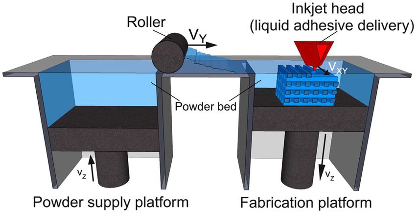
by inkjet printing liquid binder solution onto a powder bed during fabrication [14]. Another favorable characteristic
[8-10]. A wide range of materials has been utilized in print- of this technology for tissue engineering is multi-“color”
ing since most biomaterials exist in either a solid or liquid printing where each color ink can be positioned on a
state. The process begins by spreading a layer of fine pow- precise location. This feature offers the exciting potential
der material evenly across the piston. The X-Y positioning to simultaneously arrange multiple types of cells, deposit
system and the printhead are synchronized to print the de- multiple extra cellular matrix materials, and exert point-
sired 2D pattern by selective deposition of binder droplets to-point control over bioactive agents for biological tis-
onto the powder layer (Figure 1) [11]. The piston, powder sue manufacturing. In this respect, 3DP may be more
bed, and part are lowered, and the next layer of powder is flexible for printable material selection than other SFF
spread. The drop-spread-print cycle is repeated until the technologies. A wide range of biological agents such as
entire part is completed. Removal of the unbound powder peptides, proteins (e.g. fibrinogen, collagen), polysaccha-
reveals the fabricated part. The local composition can be rides (e.g. hyaluronan, alginate), DNA plasmids, and liv-
manipulated by specifying the appropriate printhead to de- ing cells have been printed with 3DP. Deposition of
posit the predetermined volume of the appropriate binder. these biological materials requires modification of indus-
The local microstructure can be controlled by altering the trial 3DP machines. Cells in particular must be kept in a
printing parameters during fabrication [12]. The incorpor- proper environment with appropriate temperature, oxy-
ation of micro-channels effectively distributed additional genation, and nutrient supply.
Other materials previously used in direct 3DP include
powder composed of a synthetic polymer (i.e. poly (ε-
caprolactone), polylactide–coglycolide or poly (L-lactic
acid)) with organic solvent as binder [10,13,15] and nat-
ural polymer powder (i.e.starch, dextran and gelatin) with
water as binder [14,16]. Indirect 3DP prints a mold which
is then cast with the final polymer and porogen materials.
Materials previously used in indirect 3DP to print the
mold include commercially available plaster powder (i.e.
calcium sulfate hemihydrate plaster powder) and water-
based binder. The mold is then cast with a slurry of
Figure 1 3D Printing schematic. 3D printing is a layer-by-layer biodegradable polymer dissolved in solvent mixed with
process of depositing liquid binder onto thin layers of powder to
porogen (i.e.polylactide–coglycolide in chloroform mixed
create a 3D object. Reproduced with permission from [11].
with NaCl) [17,18]. The resulting porous scaffold can be
Chia and Wu Journal of Biological Engineering (2015) 9:4                                                                               Page 4 of 14

seen in Figure 2 with villi-shaped pillars [17]. Tissue engi-                  An advantage of direct 3DP is direct control over both
neers have used 3DP to fabricate porous ceramic scaffolds                   the microarchitecture (i.e. pore size) and macroarchitecture
with fully interconnected channels directly from hydroxy-                   (i.e. overall shape). Prints which use porogen as the powder
apatite (HA) powder for bone replacement [16]. Custom-                      result in high pore interconnectivity, uniform porosity, and
ized anatomically shaped HA constructs can be fabricated                    defined pore size after leaching. This method has shown to
based on medical information from a patient. This technol-                  fabricate scaffolds which can support hepatocyte ingrowth
ogy also allows a construction of a biphasic scaffold to re-                [13]. Unlike indirect 3DP, there are no limitations on the
generate hybrid tissue systems such as temporomandibular                    macroarchitecture and no need for demolding. One limita-
joint (TMJ). Sherwood et al. have developed osteochondral                   tion of direct 3DP is that organic solvents can dissolve
composite constructs in which the upper region is com-                      polymers used in most printheads. To overcome this limi-
posed of D,L-PLGA/L-PLA with 90% porosity for cartilage                     tation, investigators used stencils to pattern polymer solu-
regeneration, and the lower region is composed of a L-                      tions onto porogen particles (NaCl) to fabricate scaffolds
PLGA/TCP composite to maximize bone ingrowth [19]. A                        [13]. However, the use of stencils prevents fabrication of
highly porous scaffold was created using this 3DP technol-                  highly complex shapes or small features. Organic solvent-
ogy in combination with a particulate leaching technique.                   compatible, high precision printheads are available but they
  This problem was addressed by a practical, indirect                       are optimized for a narrow range of polymeric solutions.
3DP protocol, where molds are printed and the final ma-                     Another limitation of direct 3DP is that layer thickness
terials are cast into the mold cavity [17,18]. In the indir-                must be greater than porogen particle size, and less than
ect technique, molds are printed using commercially                         150 μm maximum threshold to maintain interlayer con-
available plaster powder, and biodegradable polymers are                    nectivity and part strength during printing [12]. To over-
cast into the printed mold. Many different materials can                    come this porogen size limitation, larger pores must be
be cast under the similar printing process parameters,                      printed. One drawback of 3DP is a limited available pore
whereas individual process parameters need to be opti-                      size in the final constructs when porogens are incorporated
mized to maximize the build resolution in a conven-                         into powders prior to fabrication [15]. The shape complex-
tional direct 3DP approach. This technology could be                        ity of scaffolds is also limited when the powder material is
applied to treat patients with zygomatic bone fractures.                    degradable polymer. Also, this 3DP approach for degrad-
Lee et al. demonstrated the ability of the indirect 3DP                     able polymer demands the use of organic solvents as liquid
approach to build zygoma scaffold directly from CT data                     binders. Since organic solvents can dissolve most commer-
which can be seen in Figure 3 [17].                                         cially available drop-on-demand printhead components,

 Figure 2 PLGA scaffold with villi-shaped pillars created from indirect 3D Printing. Scaffolds are created by packing a 3D printed mold with
 porogen and polymer dissolved in solvent by indirect 3DP. The resulting scaffolds have the desired villi-shaped pillars (a) and high porosity and
 interconnectivity (b). Reproduced with permission from [17].

Chia and Wu Journal of Biological Engineering (2015) 9:4                                                                     Page 5 of 14

 Figure 3 3D printed scaffolds can be patient-specific. A zygoma was generated from CT 2D images (a,b) and zygoma-shaped scaffold was
 produced from indirect 3DP (c). Reproduced with permission from [17].

the reported studies required the use of custom machines,             with pore sizes 300-500 μm) [18]. The limitations of indir-
high resolution jets through stencils [15]. However, this ap-         ect 3DP are 1) challenges in uniform, high density packing
proach is impractical for complicated structures. Indirect            of porogen in complex features (i.e. intricate internal un-
3DP overcomes many of the limitations of direct 3DP. In               dercuts or intersecting channels) and 2) restrictions on
the indirect technique, molds are printed using commer-               shape or feature design due to difficulty demolding. Incom-
cially available modeling materials such as plaster, and bio-         plete packing will result in loss of uniform microarchitec-
degradable polymers are cast into the printed mold. Many              ture and desired macroarchitecture.
different materials can be cast under the similar printing              The key advantages of 3DP are the wide range of mate-
process parameters, whereas individual process parameters             rials able to be used due to room temperature processing
need to be optimized to maximize the build resolution in a            and the material used in powder form, ability to print
conventional direct 3DP approach. This technology could               overhangs and internal architecture, and microstructure
be applied to treat patients with zygomatic bone fractures.           control. The disadvantages of 3D Printing are the limited
The use of aqueous binder allows the use of consumer                  use of organic solvents as binders due to dissolving of
grade inkjet printheads, and eliminates the need for stencils         commercial printheads and difficulty in removing un-
[17]. The porogen size is not limited since it is introduced          bound powder from small or curved channels.
into the mold cavity after printing, and does not affect
printing resolution or layer interconnectivity. High mate-            Recent material and technology advances
rials flexibility with polymer-porogen combinations is                3DP materials include calcium polyphosphate and PVA
possible due to independence from powder material prop-               [20], HA and TCP [21-25], TCP [26-29], TCP with SrO
erties. This method can be used to create small, high aspect          and MgO doping [30,31], HA and apatite–wollastonite
ratio features (i.e. small intestine villi) or large scale, highly    glass ceramic with water-based binder [32], calcium
porous scaffolds (i.e. anatomically shaped zygoma scaffolds           phosphate with collagen in binder [33], PLGA [34], and
Chia and Wu Journal of Biological Engineering (2015) 9:4                                                                         Page 6 of 14

Farringtonite powder (Mg3(PO4)2) [35]. Materials used in                successfully used. For bioapplications, PCL is commonly
indirect 3DP gelatin preforms replaced with PCL and chi-                used due to its low melting temperature of ~60°C, low
tosan [36]. In vitro studies with bovine chondrocytes for               glass transition temperature of -60°C, and high thermal
articular cartilage tissue engineering [20], bone tissue                stability [38,40]. PLGA previously has been used with
engineering [21,22,25,26,37], monocytic cells from the                  FDM to create scaffolds, however, the high glass transition
RAW 264.7 cell line [22], human osteoblasts [23,29,32,34],              temperature of PLGA (40-60°C) makes processing PLGA
C2C12 pre-myoblastic cell line [24], and bone marrow                    challenging with a higher extrusion temperature required
stromal cells [36]. In vivo studies have been performed                 [41,42]. The material is heated to ~110-140°C to create
with rabbit calvarial bone [26], rabbit tibia bone and por-             the right material flow properties for extrusion from the
cine maxillary bone [24], rat femoral defects [28,30],                  nozzle and fusion of the layers [38,40-42]. Rheological
mouse femoral defects [33], and rabbit femoral bone [31].               modifiers can be used but must be biocompatible.
                                                                           Controllable variables are raster thickness, raster gap
Fused deposition modeling                                               width (space between rasters), raster angle, and layer
Technology description and application                                  thickness (dependent on extrusion tip diameter). This
Fused deposition modeling (FDM) is the deposition of                    results in scaffolds with controlled pore size, morph-
molten thermoplastic materials through two heated extru-                ology, and interconnectivity. The extruded molten liquid
sion heads with a small orifice in a specific laydown pat-              must be hot enough to rapidly induce fusion with previ-
tern [38]. One nozzle deposits the thermoplastic material               ously extruded material and solidify quickly to minimize
and the second deposits temporary material to support                   flow and feature size. In addition, the viscosity of the
cantilevers. In FDM, one of the traditional methods melts               material is critical to be both high enough to allow ex-
thermoplastic polymer into a semi-liquid state and the                  trusion through a fine nozzle and low enough to
head extrudes the material onto the build platform                         Scaffolds with biocompatible materials have been made
(Figure 4) [39]. The part is built in a layer-by-layer fashion          with different pore morphology and channel sizes by
where the layers are fused together. Since multiple extru-              controlling the x-y movement of the extrusion head [38].
sion nozzles could be used in FDM, each with a different                Materials can also be combined in this technology such as
material, there is no theoretical restriction on com-                   poly(ethylene glycol) terephthalate/poly(butylene tereph-
positional gradients in all three dimensions for FDM.                   thalate) or polypropylene/TCP [43,44]. Other composites
However, this has not been reduced to practice.                         such as PCL/HA or PCL/TCP are used with FDM due to
  The most important material selection criteria for                    favorable mechanical and biochemical properties for bone
FDM materials are heat transfer characteristics and rhe-                regeneration [45].
ology (behavior of liquid flow). Thermoplastics are com-                   The key advantages of FDM are high porosity due to
monly used due to the low melting temperature. PVC,                     the laydown pattern and good mechanical strength. A
nylon, ABS, and investment casting wax have been                        challenge for FDM is the limitation to thermoplastic

 Figure 4 Fused deposition modeling schematic. In fused deposition modeling, a filament of thermoplastic is heated into liquid and extruded
 through a nozzle in a specific lay-down pattern to create a scaffold. Reprinted with permission from [39].
Chia and Wu Journal of Biological Engineering (2015) 9:4 Page 7 of 14
materials with good melt viscosity properties which have can process most thermoplastics that exist as conven-
high enough viscosity to build but low enough viscosity tional injection molding pellets, without pre-processing
for extrusion. Also, these properties have limited shape into fine powders or traditional FDM filaments. It is es-
complexity for biological scaffolding materials and typic- sentially mould-free injection molding of final structures,
ally result in relatively regular structures [40]. It should making it feasible to fabricate one-of-a-kind, one patient
be noted that geometric complexity is not limited for at a time medical device [56].
FDM using industrial materials which are selected to
have optimal thermal and rheological properties but lack Stereolithography
biocompatibility. Another disadvantage for FDM is the Technology description and application
inability to incorporate living cells or temperature sensi- Stereolithography (SLA) is the regarded as the first rapid
tive biological agents during extrusion due to the high prototyping process and was developed in the late 1980s
processing temperature. [57]. The original SLA rasters a HeCd-laser beam to
spatially control the polymerization of photocurable
Recent material and technology advances resin in 2D patterns [58]. After each layer is cured, the
FDM has commonly used biocompatible polymers with platform with the cured structure attached then lowers
low melting temperatures. Materials used in FDM to in the bottom-up approach and another layer of uncured
create scaffolds are PCL and bioactive glass composites liquid resin spreads over the top. The topmost layer is
[46], L-lactide/e-caprolactone [46], PLGA with collagen now ready to be patterned. For the top-down approach,
infiltration [47], PCL-TCP with gentamicin [48], PCL- light is projected onto a transparent plate initially posi-
TCP [49], PLGA-TCP and coated with HA[42] , PCL- tioned near the bottom of the vessel holding the liquid
PLGA-TCP [50], PLGA-PCL [51], PCL coated with resin (Figure 5) [59]. After a layer is patterned through
gelatin [52], PCL [53,54], PMMA [55], and PLA [46]. In the transparent plate, the cured structure is detached
vitro studies have been performed with porcine chon- from the transparent plate. The cured structure is raised
drocytes [47], mouse pre-osteoblasts [52], and bone to allow uncured liquid resin to fill the space between
marrow-derived mesenchymal stem cell [53]. In vivo the structure and transparent plate. The next layer is
studies with murine animal models for wound healing now ready to be patterned. Since rastering a laser beam
[48], human patient for craniofacial defect [49], and can be slow, especially for large parts, the masked lamp
rabbit bone defect [42,50]. Applications include cartilage technique was developed to cure an entire layer of pho-
tissue engineering, antibiotic delivery system[48], osse- topolymers at a time. After the structure is built, the
ous craniofacial defects in humans [49,55], and bone tis- unpolymerized liquid resin is removed by draining. Post-
sue engineering [13]. curing in a UV oven converts any unreacted groups and
While the number of FDM filaments are increasing strengthens the part [60].
every month, the material choices pale in comparison to Kinetics of the curing reactions occurring during
the total number of theromoplastics that can be formed polymerization is critical. This affects the curing time
by conventional injection molding. One recent advance and the thickness of the layer polymerized. The kinetics
may vastly increase the range of materials available for can be controlled by the power of the light source, the
3D Printing, and transform it from a prototyping scanning speed and the chemistry and amount of the
method to a viable manufacturing method is to incorp- monomer and photointiators. In addition, UV absorbers
orate precision injection molding into 3D Printing gan- can be added to the resin to control the depth of
try. This combination has significant potential because it polymerization [61].
Figure 5 Stereolithography schematic. Stereolithography is the polymerization of photocurable resin by a bottom-up system with scanning
laser (left) or top-down setup with digital light projection (right). Reproduced with permission [59].Chia and Wu Journal of Biological Engineering (2015) 9:4 Page 8 of 14 Materials must have photocurable moieties for photo- ensure alignment of layers. Dynamic mask projection crosslinking. Typical materials used in STL include SLA has been able to achieve a lateral resolution of ∼ 2 acrylics and epoxies. For tissue engineering applications, μm, and vertical resolution of ∼ 1 μm for PPF resin [68]. there are very few biodegradable and biocompatible bio- The microstructures able to be produced with this tech- materials that are dimensionally stable during photopoly- nology are extremely detailed although there are still merization. Photocrosslinkable poly(propylene fumarate) challenges of creating horizontal channels and prevent- (PPF) [62] is commonly used in SLA and has been used to ing shrinkage of structures. fabricate complex 3D scaffolds with controlled micro- SLA recently has increased the library of resins with structures for reconstruction of rabbit cranial defects [58]. biodegradable moieties and the encapsulation of cells PPF requires a reactive diluent, such as diethyl fumarate during processing. Novel macromers synthesized include or N-vinyl-2-pyrrolidone, to reduce the viscosity of the segments of PCL (three-armed hydroxyl-terminated) resin for proper processing conditions [63]. These diluents [69] or poly(D,L-lactide) [63,70,71]. Photo-curable poly introduce significant amounts of a non-degradable com- (D,L-lactide) (PLLA) resin without the use of reactive ponent. Resins with and without bioceramic dispersions diluents has been developed and applied in SLA [70]. have been processed by SLA. The end groups are modified to acrylate or methacrylate Medical applications of SLA include the fabrication of to allow for photo-crosslinking capability. Another resin anatomical models for pre-surgical planning, and indir- recently used in making SLA scaffolds is PPF-DEF [72,73] ect fabrication of medical devices by using the SLA pat- and PPF-DEF with BMP-2 loaded PLGA microspheres terns for molds (e.g. filling a SLA structure to use as a [74]. PPF-DEF or PPF-DEF with HA is used in μSL (
Chia and Wu Journal of Biological Engineering (2015) 9:4                                                                Page 9 of 14

                                                                        post processing (e.g. extra sintering in an oven) in-
                                                                        creases part strengths but can cause shrinkage of the
                                                                        parts. A biocomposite blend of polyvinyl alcohol (PVA)
                                                                        and hydroxyapatite (HA) was also used in SLS [89]. HA
                                                                        particles were coated with a water-soluble PVA via
                                                                        spray-drying or physical blending. These parts were
                                                                        used for craniofacial and joint defect applications.
                                                                        Williams et al. fabricated PCL scaffolds with porous
                                                                        architecture and sufficient mechanical properties for
                                                                        bone tissue engineering applications [90].
                                                                          This technique is also feasible with medical data to cre-
                                                                        ate anatomy specific structures. A mandibular condyle
 Figure 6 Selective laser sintering schematic. Selective laser          scaffold was demonstrated in this technique using CT data
 sintering uses a laser to fuse together powder particles to create a   from a pig condyle [90]. The integration of computational
 3D scaffold. Thin layers of powder are spread between each fused
 layer. Reprinted with permission from [83].
                                                                        design and SLS techniques enables the ability to fabricate
                                                                        scaffolds that have anatomically shaped external architec-
                                                                        tures and porous interior structure. FDA clearance was re-
layer is formed and is bound to the previous layer. Un-                 cently awarded for the use of SLS to process medical
bound, loose powder is removed after the part is com-                   grade polyether ether ketone (PEEK) to make custom cra-
pleted and is heat treated to achieve full density.                     niofacial implants. More recently, SLM was used to create
Temporary support structures are not needed, unlike in                  the first patient-specific, ready for implantation titanium
SLA, since unbound solid particles support any cantilever               mandible that accepts dental implants to support a man-
structures. Since sintering does not result in complete                 dibular denture [91].
melting of the powder particle, the porosity between the                  They key advantage of SLS/SLM/EBM is the ability to
original particles can be preserved, and a wide range of                directly make metallic implants that promote either bone
pure and mixture of materials can be processed.                         ingrowth and regeneration for load-bearing applications in
   While solid state sintering can be achieved for most                 which high fracture toughness and mechanical strength
materials between 0.5-1 Tmelting, selective laser melting               are needed. Even for non-load bearing applications, poly-
(SLM) and electron beam melting (EBM) use intense en-                   mers can be processed without the use of organic solvent.
ergy to heat the powder above Tmelting to completely fuse               It is slightly easier to achieve compositional gradients in
the particles into one fully-dense, consolidated structure.             SLS than SLA by spreading different powder between dif-
In In practice, melting is more easily accomplished if all              ferent vertical layers, but compositional gradients in the
powder has a single melting point, and is therefore more                horizontal plane is very limited. The main disadvantages
easily accomplished with pure metals than with alloys                   are limited materials which fuse but do not decompose
due to variation in liquid metal flow behavior, surface                 under the laser beam (high temperatures) and the post
tension, and laser-material interactions. Therefore, the                processing needed to remove trapped powder. Another
range of materials for SLM is more limited than SLS.                    limitation is the condution and diffusion of laser heat
   The resolution of features is determined by powder par-              causes unwanted fusion of neighboring powder particles,
ticle size, focused laser beam diameter and heat transfer in            limiting the resolution of final features. Lastly, smaller
the powder bed. The limit to particle size is 10 um due to              pore sizes are limited since the created pores depend on
poor spreading and sintering too quickly causing edge in-               the particle size of the powder used. Powder particles too
accuracies. Materials commonly used are PCL and a com-                  small cannot be used due to poor spreading from powder
bination of polyether ether ketone and hydroxyapatite                   clumping.
[84-87]. With biomaterials, thin solid disks are commonly
made but feature are made on the ~400-500 μm scale.                     Recent material and technology advances
   Previously coated ceramic powders and thermoplastics                 Recent advances of SLS have been the ability to produce
have been used in SLS. Intermediate binding materials are               lower stiffness scaffolds and higher resolution features.
required because of an excessively high glass transition                PCL scaffolds have been produced at lower stiffness of
temperature and the melting point of ceramic powder.                    300-400 kPa [87] than reported before at 14.9-113.4
The intermediate binding materials would melt before the                MPa [85,86,90,92]. This lower stiffness allows for appli-
ceramic powder and fuse together the ceramic particles.                 cations of soft tissue engineering such as cardiac tissue.
Tan et al. fabricated calcium phosphate bone implants by                  Work has been done to streamline the CAD/CAM
sintering calcium phosphate powder coated with polymer                  process of making functionally graded scaffolds (FGS,
[88]. After the part is built and excess powder removed,                changing stiffness within a part) by using a library of
Chia and Wu Journal of Biological Engineering (2015) 9:4 Page 10 of 14
polyhedrals to control the porosity. The porosity then needed. In addition, hydrogels created in this method
processed is related to the stiffness of the scaffold and have low stiffness which may result in collapse of struc-
demonstrated with PCL in SLS [93]. A thorough review tures or limitations on complexity of shapes.
on the development of the design of microarchitecture Similarly, bioprinting is the fabrication of hydrogel
can be found [94]. In addition, FEA has been used to structures with direct incorporation of cells (Figure 7).
help design microarchitecture and predict mechanical Cells are added during processing in cell printing strat-
properties for SLS [92,95]. egies such as alginate-cell (bovine chondrocytes) solution
For SLS, common materials used are PCL and HA extruded from a syringe [110], electrostatically driven ink-
[92,96,97], PCL and β-TCP with collagen coating [98], jet printing of bovine vascular endothelial cells in culture
Ca-P/PHBV and CHAp/PLLA [99,100], and PVA [101]. medium [111], laser-guided direct writing of embryonic
To demonstrate encapsulation of biomolecules, BSA was chick spinal cord cells [112], and laser-induced forward
encapsulated in Ca-P/PHBV microparticles and processed transfer of cells suspended in alginate [113]. This technol-
[102]. In vitro studies have been performed with C2C12 ogy provides a controlled spatial distribution of cell or
myoblast cells for cardiac tissue engineering [87], SaOS-2 growth factors as well as the scaffold structures. However,
cells [99], human bone marrow stromal cells [103], and this fabrication technique is generally limited to hydrogel
human osteoprogenitor cells [52], porcine adipose-derived materials such as alginate and fibrin, which may not be
stem cells [98,104], and MG-63 [101] for bone tissue en- ideal for the implantation in biological environments that
gineering. In vivo studies have been performed in nude require strong mechanical properties. Example applica-
mice showed better woven bone and vascular tissue for- tions are rat smooth muscle cell-laden collagen droplets
mation [98]. Applications are bone tissue engineering and (650 μm diameter) to create specific cell spatial patterns in
interbody cages for spinal fusions [97]. 3D [114]. This SFF method is especially good for low vis-
cosity materials and the buoyancy due to the density
3D Plotting/Direct-write bioprinting matching of the extruded material to the liquid medium
Technology description and application prevents collapse of the shape. The strand thickness can
3D plotting was developed at the Freiburg Materials be varied by material viscosity, deposition speed, extrusion
Research Center in 2000 to create soft tissue scaffolds. 3D tip diameter, and applied pressure.
plotting is based on extruding a viscous liquid material The key advantages of bioprinting are the room tem-
(generally a solution, paste, or dispersion) from a pressur- perature processing (if applicable), direct incorporation
ized syringe into a liquid medium with matching density. of cells, and homogenous distribution of cells. The key
The material is deposited in one long continuous strand disadvantages are limited mechanical stiffness, critical
or in individual dots from a nozzle or syringe to create a timing of gelation time, specific matching of material
desired 3D shape of ceramics, polymers, or hydrogels and liquid medium densities to preserve shapes, and low
[105]. The process can be at room temperature or at ele- resolution. Further development of materials that are
vated temperatures, but does not involve thermoplastics optimal for biofactor printing, and next generation print-
as in FDM. heads that can separately deposit multiple biofactors and
This SFF method is particularly applicable for natural materials onto the same platform, will provide the
biomaterials to create hydrogels. Landers et al. used ther-
moreversible natural polymers such as agar and gelatin in
solution. The solution is heated and extruded at ~80°C
into a cooler liquid medium (~20°C) of gelatin or silicone
oil to quickly solidify the heated solution. [106,107]. An-
other approach is to extrude polymers into a liquid
medium containing reactants for crosslinking. An example
material is extruding gelatin into a Ca2+ reservoir for mi-
crovasculature [108]. For other materials such as TCP, a
solution is made with water, extruded from a syringe, and
then lyophilized to remove the liquid [109]. The resulting
diameter of each strut was ~400 μm.
The key advantages are material flexibility and room
temperature processing (if applicable). In addition, many
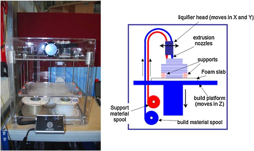
of the other SFF technologies cannot use natural poly- Figure 7 Bioprinting schematic. In bioprinting, small balls of
mers due to processing conditions. One key disadvan- bioink composed of cells and hydrogel materials (e.g. alginate or
decellularized extracellular matrix) are printed in a desired shape.
tage is the difficulty in fabricating complex shapes with
Reproduced with permission from [11].
overhangs since a temporary, sacrificial material isChia and Wu Journal of Biological Engineering (2015) 9:4 Page 11 of 14
potential to create constructs satisfying complex bio- for oxygen transport to cells, resulting in a maximum of
logical requirements of tissue engineering scaffolds. 400 μm diameter features for cell survival [128]. For both
SLS and 3DP, there is a challenge with creating stronger
Recent material and technology advances structures without increasing dimensions. To create small
Bioplotting materials include PLGA, TCP, collagen and features which survives the fabrication process, powder
chitosan [109], chitosan [115], collagen-alginate-silica particles much be bound together tightly. By increasing
composites coated with HA [116], soy protein [117,118], the strength of the laser for SLS or amount of binder for
and agarose with gelatin [107]. In vitro studies have been 3DP, additional powder particles would bind and therefore
performed with mouse pre-osteoblasts [116] and human increase the dimensions. Additional work is needed to
mesenchymal stem cells [117]. In vivo studies have been move SLS and 3DP to resolutions below 400-500 μm. In
performed in ovine cavalarial defects [109]. Applications addition, unbound trapped powder is difficult to remove
include bone tissue engineering [109,116], tissue regen- from small channels. Future work is needed to create pow-
eration [118]. der that is easily removable with traditional methods of
Bioprinting materials are agarose with human umbil- high-pressured air. One strategy is to create spherical
ical vein smooth muscle cells (HUVSMCs) and human powder particles which would facilitate removal in tight
skin fibroblasts (rods) [119], gelatin-HA-tetraPEG-DA spaces.
with NIH 3T3s (rods) [120], rat primary bladder smooth While SLA can reach extremely high resolutions, there
muscle cells in collagen droplets [114], human micro- are a limited number of biodegradable, biocompatible
vascular endothelial cells in fibrin (inkjet printer) [121], resins. Advances have been made to synthesize new
and alginate droplets [108]. Applications are mainly for macromers with biodegradable moieties, however, these
vascular tissue engineering [108,119-121]. materials have not been FDA approved. FDM, SLS, and
Recent studies show the ability to bioprint single cells 3DP are able to use polymers such as PLGA, PLLA, and
and cell-laden hydrogel-PCL scaffolds. High throughput PCL without chemical modification which will help ex-
printing of single-cell arrays has been shown with pedite future FDA approval for biomedical devices.
“Block-Cell-Printing” [122]. Microfluidic arrays of hook- Although macro and microarchitecture has made great
shaped traps are used to trap single cells. Trapped cells strides in the past five years, additional work should
can be paired and separated 5 μm to study cell com- focus on the nanoarchitecture (e.g. biochemical mole-
munication. In this study, trapped primary rat cortical cules). Due to harsh processing conditions of SFF
neurons were cultured and cells exhibited neuronal methods (e.g. heat, organic solvent), biochemical mole-
morphology. Ahn et al. bioprinted high density cell- cules are not generally incorporated directly into the
laden hydrogels by extruding a 4°C cell-alginate solution scaffold. While biochemical molecules can be coated
onto a -10°C stage to create a structure [123]. The algin- onto structures in post-processing, there is a need for
ate was crosslinked to provide strength by incubating sustained growth factor release over time. Therefore,
the structure in a CaCl2 solution. Good cell viability of strategies to incorporate biochemical molecules directly
was shown for human mesenchymal stem cells and into scaffolds for prolonged release will be needed.
human osteoblast-like cells after processing. Lastly, a layer- Although the focus of this review article is on the fabri-
by-layer process has alternately deposited chondrocyte- cation techniques and biomaterials used in 3DP, the deg-
laden hydrogel droplets (alginate or decellularized radation kinetics and byproducts of the materials are in
extracellular matrix bioink) and PCL in a layer-by-layer fact a very significant problem in 3D scaffolds due to mass
process to create a 3D structure [124-126] (Figure 7). transport limitations within thick scaffolds. This is a mov-
Recent advances in biofactor printing technology allow ing boundary diffusion-reaction problem that even with-
the simultaneous printing of pharmaceutical and bio- out biodegradable biomaterials can result in hypoxia and
logical agents during fabrication. Xu et al. demonstrated acidosis within the scaffolds. The release of acidic degrad-
that inkjet printing technology can precisely place the ation products is expected to worsen the acidosis which
cells and proteins into 3D alginate structures [127]. may harm the seeded cells and/or the surrounding cells”.
Competing interests
Future direction The authors declare that they have no competing interests.
Additional progress for 3D Printing technologies is
needed for increasing resolution without sacrificing Authors’ contributions
HNC and BMW conceived, wrote, and edited the manuscript. Both authors
shape, strength, and handability of scaffolds. Anatom- have read and approved the final manuscript.
ical features and tissue architecture may have details on
the scale of hundreds of microns (e.g. villi of the small Author details
1
Department of Bioengineering, Henry Samueli School of Engineering,
intestine with ~500 um diameters). Diffusion consump- University of California, 5121 Engineering V, Los Angeles, CA 90095, USA.
tion modeling has shown a 200 μm limit in scaffolds 2
Department of Materials Science and Engineering, Henry Samueli School ofChia and Wu Journal of Biological Engineering (2015) 9:4 Page 12 of 14
Engineering, University of California, Los Angeles, CA 90095, USA. 3Division of Characterization and biocompatibility investigations. J Biomed Mater Res B
Advanced Prosthodontics, School of Dentistry, University of California, Los Appl Biomater. 2010;93:212–7.
Angeles, CA 90095, USA. 4Department of Orthopedic Surgery, School of 24. Abarrategi A, Moreno-Vicente C, Martínez-Vázquez FJ, Civantos A, Ramos V,
Medicine, University of California, Los Angeles, CA 90095, USA. Sanz-Casado JV, et al. Biological properties of solid free form designed ceramic
scaffolds with BMP-2: in vitro and in vivo evaluation. PLoS One. 2012;7:e34117.
Received: 9 September 2014 Accepted: 17 January 2015 25. Becker ST, Bolte H, Krapf O, Seitz H, Douglas T, Sivananthan S, et al.
Endocultivation: 3D printed customized porous scaffolds for heterotopic
bone induction. Oral Oncol. 2009;45:e181–e8.
26. Tamimi F, Torres J, Gbureck U, Lopez-Cabarcos E, Bassett DC, Alkhraisat MH,
References et al. Craniofacial vertical bone augmentation: a comparison between 3D
1. Karande TS, Ong JL, Agrawal CM. Diffusion in musculoskeletal tissue printed monolithic monetite blocks and autologous onlay grafts in the
engineering scaffolds: design issues related to porosity, permeability, rabbit. Biomaterials. 2009;30:6318–26.
architecture, and nutrient mixing. Ann Biomed Eng. 2004;32:1728–43. 27. Butscher A, Bohner M, Roth C, Ernstberger A, Heuberger R, Doebelin N,
2. Hollister SJ. Porous scaffold design for tissue engineering. Nat Mater. et al. Printability of calcium phosphate powders for three-dimensional
2005;4:518–24. printing of tissue engineering scaffolds. Acta Biomater. 2012;8:373–85.
3. Stevens MM, George JH. Exploring and engineering the cell surface 28. Tarafder S, Balla VK, Davies NM, Bandyopadhyay A, Bose S. Microwave‐
interface. Science. 2005;310:1135–8. sintered 3D printed tricalcium phosphate scaffolds for bone tissue
4. Winder J, Bibb R. Medical rapid prototyping technologies: state of the art engineering. J Tissue Eng Regen Med. 2013;7:631–41.
and current limitations for application in oral and maxillofacial surgery. 29. Santos CF, Silva AP, Lopes L, Pires I, Correia IJ. Design and production of
J Oral Maxillofac Surg. 2005;63:1006–15. sintered β-tricalcium phosphate 3D scaffolds for bone tissue regeneration.
5. Colin A, Boire J-Y. A novel tool for rapid prototyping and development of Mater Sci Eng C. 2012;32:1293–8.
simple 3D medical image processing applications on PCs. Comput Methods 30. Tarafder S, Davies NM, Bandyopadhyay A, Bose S. 3D printed tricalcium
Programs Biomed. 1997;53:87–92. phosphate bone tissue engineering scaffolds: effect of SrO and MgO
6. Winder J. Medical rapid prototyping and 3D CT in the manufacture of doping on in vivo osteogenesis in a rat distal femoral defect model.
custom made cranial titanium plates. J Med Eng Technol. 1999;23:26–8. Biomater Sci. 2013;1:1250–9.
7. Hollister S, Maddox R, Taboas J. Optimal design and fabrication of scaffolds 31. Tarafder S, Dernell WS, Bandyopadhyay A, Bose S. SrO‐and MgO‐doped
to mimic tissue properties and satisfy biological constraints. Biomaterials. microwave sintered 3D printed tricalcium phosphate scaffolds: Mechanical
2002;23:4095–103. properties and in vivo osteogenesis in a rabbit model. J Biomed Mater Res
8. Cima MJ, Sachs E, Cima LG, Yoo J, Khanuja S, Borland SW, et al. Computer- Part B: Appl Biomat. 2014
derived microstructures by 3D printing: bio-and structural materials. Solid 32. Suwanprateeb J, Sanngam R, Suvannapruk W, Panyathanmaporn T.
Freeform Fabr Symp Proc: DTIC Document; 1994. p. 181-90 Mechanical and in vitro performance of apatite–wollastonite glass ceramic
9. Griffith LG, Wu B, Cima MJ, Powers MJ, Chaignaud B, Vacanti JP. In Vitro reinforced hydroxyapatite composite fabricated by 3D-printing. J Mater Sci
Organogenesis of Liver Tissuea. Ann N Y Acad Sci. 1997;831:382–97. Mater Med. 2009;20:1281–9.
10. Wu BM, Borland SW, Giordano RA, Cima LG, Sachs EM, Cima MJ. Solid free-form 33. Inzana JA, Olvera D, Fuller SM, Kelly JP, Graeve OA, Schwarz EM, et al. 3D
fabrication of drug delivery devices. J Control Release. 1996;40:77–87. printing of composite calcium phosphate and collagen scaffolds for bone
11. Billiet T, Vandenhaute M, Schelfhout J, Van Vlierberghe S, Dubruel P. A regeneration. Biomaterials. 2014;35:4026–34.
review of trends and limitations in hydrogel-rapid prototyping for tissue 34. Ge Z, Wang L, Heng BC, Tian X-F, Lu K, Fan VTW, et al. Proliferation and
engineering. Biomaterials. 2012;33:6020–41. differentiation of human osteoblasts within 3D printed poly-lactic-co-gly-
12. Wu BM, Cima MJ. Effects of solvent‐particle interaction kinetics on colic acid scaffolds. J Biomater Appl. 2009;23:533–47.
microstructure formation during three‐dimensional printing. Polymer Eng 35. Klammert U, Vorndran E, Reuther T, Müller FA, Zorn K, Gbureck U. Low
Sci. 1999;39:249–60. temperature fabrication of magnesium phosphate cement scaffolds by 3D
13. Kim SS, Utsunomiya H, Koski JA, Wu BM, Cima MJ, Sohn J, et al. Survival and powder printing. J Mater Sci Mater Med. 2010;21:2947–53.
function of hepatocytes on a novel three-dimensional synthetic biodegradable 36. Lee J-Y, Choi B, Wu B, Lee M. Customized biomimetic scaffolds created by
polymer scaffold with an intrinsic network of channels. Ann Surg. 1998;228:8. indirect three-dimensional printing for tissue engineering. Biofabrication.
14. Lam CXF, Mo XM, Teoh SH, Hutmacher DW. Scaffold development using 3D 2013;5:045003.
printing with a starch-based polymer. Mater Sci Eng C. 2002;20:49–56. 37. Bose S, Vahabzadeh S, Bandyopadhyay A. Bone tissue engineering using 3D
15. Zeltinger J, Sherwood JK, Graham DA, Müeller R, Griffith LG. Effect of pore printing. Mater Today. 2013;16:496–504.
size and void fraction on cellular adhesion, proliferation, and matrix 38. Zein I, Hutmacher DW, Tan KC, Teoh SH. Fused deposition modeling of
deposition. Tissue Eng. 2001;7:557–72. novel scaffold architectures for tissue engineering applications. Biomaterials.
16. Seitz H, Rieder W, Irsen S, Leukers B, Tille C. Three‐dimensional printing of 2002;23:1169–85.
porous ceramic scaffolds for bone tissue engineering. J Biomed Mater Res B 39. van Noort R. The future of dental devices is digital. Dent Mater. 2012;28:3–12.
Appl Biomater. 2005;74:782–8. 40. Hutmacher DW, Schantz T, Zein I, Ng KW, Teoh SH, Tan KC. Mechanical
17. Lee M, Dunn JCY, Wu BM. Scaffold fabrication by indirect three-dimensional properties and cell cultural response of polycaprolactone scaffolds designed
printing. Biomaterials. 2005;26:4281–9. and fabricated via fused deposition modeling. J Biomed Mater Res.
18. Lee M, Wu BM, Dunn JCY. Effect of scaffold architecture and pore size on 2001;55:203–16.
smooth muscle cell growth. J Biomed Mater Res A. 2008;87:1010–6. 41. Park SH, Park DS, Shin JW, Kang YG, Kim HK, Yoon TR, et al. Scaffolds for
19. Sherwood JK, Riley SL, Palazzolo R, Brown SC, Monkhouse DC, Coates M, bone tissue engineering fabricated from two different materials by the
et al. A three-dimensional osteochondral composite scaffold for articular rapid prototyping technique: PCL versus PLGA. J Mater Sci Mater Med.
cartilage repair. Biomaterials. 2002;23:4739–51. 2012;23:2671–8.
20. Shanjani Y, Croos D, Amritha J, Pilliar RM, Kandel RA, Toyserkani E. Solid 42. Kim J, McBride S, Tellis B, Alvarez-Urena P, Song Y-H, Dean DD, et al.
freeform fabrication and characterization of porous calcium polyphosphate Rapid-prototyped PLGA/β-TCP/hydroxyapatite nanocomposite scaffolds in a
structures for tissue engineering purposes. J Biomed Mater Res B Appl rabbit femoral defect model. Biofabrication. 2012;4:025003.
Biomater. 2010;93:510–9. 43. Woodfield TB, Malda J, De Wijn J, Peters F, Riesle J, van Blitterswijk CA.
21. Seitz H, Deisinger U, Leukers B, Detsch R, Ziegler G. Different Calcium Design of porous scaffolds for cartilage tissue engineering using a three-
Phosphate Granules for 3‐D Printing of Bone Tissue Engineering Scaffolds. dimensional fiber-deposition technique. Biomaterials. 2004;25:4149–61.
Adv Eng Mater. 2009;11:B41–B6. 44. Kalita SJ, Bose S, Hosick HL, Bandyopadhyay A. Development of controlled
22. Detsch R, Schaefer S, Deisinger U, Ziegler G, Seitz H, Leukers B. In vitro- porosity polymer-ceramic composite scaffolds via fused deposition
osteoclastic activity studies on surfaces of 3D printed calcium phosphate modeling. Mater Sci Eng C. 2003;23:611–20.
scaffolds. J Biomater Appl. 2010. 45. Rai B, Teoh SH, Ho KH, Hutmacher DW, Cao T, Chen F, et al. The effect of
23. Warnke PH, Seitz H, Warnke F, Becker ST, Sivananthan S, Sherry E, et al. rhBMP-2 on canine osteoblasts seeded onto 3D bioactive polycaprolactone
Ceramic scaffolds produced by computer‐assisted 3D printing and sintering: scaffolds. Biomaterials. 2004;25:5499–506.You can also read