SAFETY N W - Land Transport Authority
←
→
Page content transcription
If your browser does not render page correctly, please read the page content below
SAFETY

                                                                                NEWS
30th EDITION / ISSN 1793-1665 SEP 2015

FEATURED ARTICLES
02 LTA 4th Corporate Safety Retreat          08 Managing Drainage at Work Zone
04 Environmental Impact Assessment in LTA    10 	Safety Considerations in North-East
06 	Body Temperature Regulating             		 Line Additional Trains Project
     Mechanisms and Heat Related Disorders
     at Construction Work Sites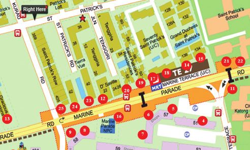
[2]         LTA 4th Corporate Safety Retreat

BACKGROUND                                                        Pre-Retreat Workshops

Since 2007, LTA has held its safety retreats with the primary     In preparation for the 4th Corporate Safety Retreat, the
objective of creating a forum for LTA’s Senior Management         various root causes identified earlier by Safety Division
and key Project Management staff to review LTA’s safety           were shared with all the Roads, Rail and Engineering
performance, set safety targets and establish new initiatives     project teams. The Directors / Project Directors heading
aimed at achieving Zero Accident within LTA worksites.            the various project teams then conducted workshops with
                                                                  their project teams and contractors to brainstorm ideas to
Over the years LTA has been placing significant resources         address these accident root causes. The strategies and
and efforts in its enhancement of construction safety through     initiatives developed during these workshops would be
the improving of knowledge sharing, safety specifications,        used subsequently at the safety retreat, allowing the Senior
enforcement and the implementation of initiatives. This           Management to make an informed decision on the way
culminated in the launch of the Zero Accident Movement            forward.
at the Annual Safety Award Convention 2012 on 18
September 2012.                                                   Pre-Retreat Study Trip

However, despite the added emphasis and efforts, there            In preparation for the Safety Retreat, Safety Division also
were still several serious accidents that occurred on LTA         organised a study trip to Infineum Singapore Pte Ltd,
worksites in the past two years. Hence, Safety Division           a petrochemical company located on Jurong Island to
organised the 4th Corporate Safety Retreat to take stock of       glean best safety practices that can be replicated on LTA
the current safety situation, analyse the accident trends and     worksites as well. Infineum Singapore Pte Ltd has been
cause, and formulate initiatives to achieve LTA’s vision of       recognised by MOM as a safety excellent organisation at
Zero Accident on our worksites.                                   their annual Workplace Safety & Health Awards. The study
                                                                  trip was conducted on 11 December 2014 and included
PRE-RETREAT                                                       representatives from Rail, Roads and Engineering project
                                                                  teams.
Analysis of Accident Data
                                                                  LTA 4th CORPORATE SAFETY RETREAT
To aid in identifying areas for improvement, an analysis
was conducted on the root causes of all the accidents that        The LTA 4th Corporate Safety Retreat was held at Seletar
occurred on LTA worksites in the past two years. A total of       Country Club on 29 January 2015 and was attended by 163
eight root causes were identified and categorised into three      participants consisting of both LTA and Contractors. The
key areas for improvement:                                        retreat was a half day event with the following agenda:

   •     Mindset and personal commitment                          1) Review of past years’ safety performances;
   •     Competency                                               2) Setting of safety targets for 2015 to 2020;
   •     Innovative design and cutting edge technology            3) Presentation and discussion on safety initiatives; and
                                                                  4)	Agreement on the safety initiatives and new safety
 Areas for Improvement                Root Causes                     targets by Senior Management.

                             Inconsistent Safety                  Besides the LTA Project Management Staff, young engineers
                             Performance of Contractors           were also nominated to attend the retreat. The approach
                             Poor Safety Performance              gave them a good opportunity to learn and be involved in
   Mindset & Personal        of New and / or Local                discussions. This would help reinforce them with a safety
      Commitment             Contractors                          mindset of ownership and pursuing safety excellence in LTA
                             Lack of Commitment                   projects.
                             between Civil and SWC
                             Contractors                          In a break from past retreats, the Senior Management from
                                                                  LTA’s contractors were also invited to the Safety Retreat.
                             Gaps in Communication and            Their involvement in the retreat enabled LTA to get these
                             Supervision                          contractors’ commitment and buy-in to LTA’s vision of
         Competency          Inadequate Skills Set and            achieving Zero Accident on their respective worksites.
                             Unsafe Attitude
                             Gaps in Safe Work Practices
                             Lack of Consideration for
       Innovative Design     Constructability
         Cutting Edge        Over Reliance on Manual
          Technology         Labour (Recurring Hand
                             Injuries)

Figure 1: Three key areas for improvement in Safety Performance
                                                                   Figure 2: LTA Chief Executive Mr. Chew Men Leong giving the
                                                                               opening address at the Safety Retreat
[3]

In his opening speech, LTA Chief Executive Mr. Chew Men             12.	In-house production of hand injury videos on manual
Leong took the opportunity to share that LTA believes in                handling
investing new technology and providing training to further          13.	Safety induction seminar for new tenderers as a pre-
raise the safety standards on site. LTA is committed to                 requisite for tender submission
improving the safety and productivity of its workforce by           14.	Reward scheme by contractors for site supervisors who
mandating the requirement for more skilled workers in its               maintain a safe team
projects.                                                           15.
                                                                        Limit in-situ reinforce concrete works with design
                                                                        considerations to enable precast modular elements
Mr. Chew ended his speech by reminding all that as LTA              16.
                                                                        Strut-less excavation for station construction through
increases its number of projects, one of the greatest                   Continuous Bored Piles (CBP) with ground anchors
challenge is to instil a safety-first mindset, and thus for real
change to take place, there must be ownership and “safety           With the 16 initiatives selected, Directors were nominated
starts with each and every one of us”.                              to champion these initiatives and to ensure that these
                                                                    strategies are carried out effectively across LTA construction
                                                                    sites.

                                                                    New Safety Targets

                                                                    The setting of new safety targets was also determined at
                                                                    the Safety Retreat.

                                                                             Proposed Safety Targets for 2015-2020
                                                                                   2015     2016    2017     2018    2019        2020
                                                                      Accident
                                                                     Frequency      0.9     0.81     0.73    0.66     0.59       0.53
                                                                     Rate(AFR)

                                                                      Severity
                                                                      Rate(SR)       20      18       16      14       12         11

                                                                               Figure 4: LTA’s Corporate Safety Targets

  Figure 3: Discussion on the merits of the initiatives proposed

Proposed Safety Initiatives

Through the presentations made by Safety Division and the
Directors, as well as the robust discussions that transpired
at the retreat, a total of 16 safety initiatives were shortlisted
to be implemented on LTA projects:

1.	Compulsory combined Civil / E&M Planned General
    Inspections                                                           Figure 5: Group photo of Safety Retreat participants
2.	Safety considerations in Combined Services Drawings                                commemorating the event
    (CSD), Structural Electrical and Mechanical (SEM) and
    Coordinated Installation Programme (CIP)                        CONCLUSION
3. Safety Engagement Programme (SEP)
4.	Mechanise to remove the need for hazardous works                The LTA 4th Corporate Safety Retreat has provided a timely
5. Improve on equipment design for ease of bulk handling            forum for the stock taking of LTA’s current safety situation,
6.	Establishment of work zones for full responsibility and         to better understand the safety challenges faced, close
    ownership                                                       possible gaps in the work process and to forge ahead with
7. Corporate safety audits and reviews                              new initiatives to achieve LTA’s vision of Zero Accident
8.	Empowering senior / experienced workers to take on              across all LTA projects.
    roles as charge hands
9.	Empowering workers to conduct safety training in their
    native language with demonstrations
10.	In-house assessments for supervisors in individual
    native languages to ensure competency                                                                           Kevin Seet
11.
    Standardise operational procedures across different                                    Assistant Safety and Health Manager
    projects                                                                                                     Safety Division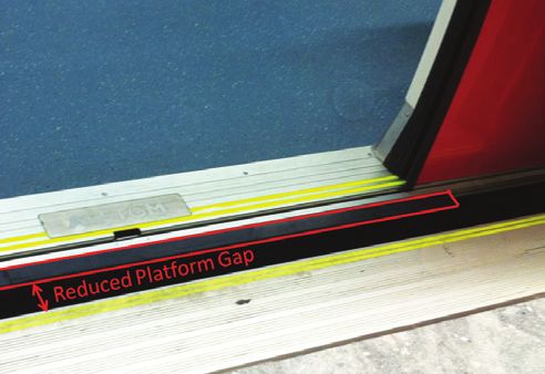
[4] ENvironmental impact assessment in lta
INTRODUCTION The EIA study provides a means for decision makers
to better integrate environmental, human health, socio-
As LTA embarks on more projects to enhance economic concerns through systematic examination of the
commuters connectivity and support Singapore’s long- environmental implications of a project.
term infrastructure development, ‘Environmental Impact
Assessment’ (EIA) is now an indispensable part of our 2) EIA Encourages Environmentally-Sensitive
projects. This is a process by which the anticipated effects Project Design
on the environment of a proposed development or project
(during construction and operation) are assessed. If the Secondly, through the identification of potential
likely impacts are significant, design measures or other environmental impacts from project proposals, design
relevant mitigation measures can be taken to reduce or changes or mitigation measures can also be proposed to
avoid those impacts. avoid or reduce the significant impacts. Improved designs
can be made through early consideration of project impacts
ADOPTION OF EIA IN THE WORLD during the design phase, through ongoing discussions
between the design team and EIA consultants.
Since the 1960s, there has been growing public awareness
of the interaction between development actions and their EIA IN LTA
environmental consequences. In developed countries,
consistent calls have been made for human health, Recognising the value of EIA studies in our development
amenity and ecological concerns to be explicitly considered projects, LTA require EIAs to be conducted for major rail
in development decisions. Initially, the response taken to and road infrastructure projects even though most of LTA’s
environmental problems was reactive, focusing on ‘end- projects do not fall under URA’s criteria. EIA has been
of-pipe’ solutions. However, the value of an ‘anticipate conducted for LTA railway lines and expressways (e.g.
and prevent’ approach is now recognised, and the focus Down Town Line, Marina Coastal Expressway, Thomson-
for environmental action has shifted from rectification to East Coast Line, North-South Expressway) to evaluate the
prevention. environmental impacts due to the projects.
Hence, EIA was first introduced in the USA nearly 40 EIAs are usually conducted during the Architectural /
years ago, as a government response to demands for Engineering (AE) phase, where the objective is to develop
environmental effects to be formally considered in the mitigation measures to minimise environmental impacts
planning of development projects. Since then, EIA has to the physical environmental and human population.
become a formal process in many countries, and is currently Through the use of quantitative, semi-quantitative and
practiced in more than 100 countries. EIA as a mandatory qualitative techniques, the EIA Consultants can predict the
regulatory procedure is also adopted in countries including impact magnitude, evaluate its significance (importance)
EU member countries, and even Asian countries like and identify mitigation measures to minimise the impacts.
Malaysia, Hong Kong and Taiwan. The remaining impacts (residual impacts) will then be
evaluated, and if it is still deemed unacceptable, more
While there is currently no regulation to mandate the conduct mitigation measures will be developed to further reduce
of EIA in Singapore, the Urban Redevelopment Authority them to an acceptable level. The recommendations from
(URA) does have its own requirements for conducting EIA. the study are then cascaded to the construction phase for
A set of criteria has been established to identify projects the Contractors to adapt for site specific implementation.
that have the potential in resulting significant environmental
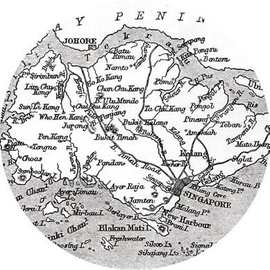
impacts, for instance projects that affect sensitive areas HOW EIA IS UTILISED IN LTA’S WORKS
(such as nature reserves, marine works), or when projects
can potentially cause trans-boundary impact. By conducting the EIA study before the construction
phase, it allows Contractors and Project Teams to better
PURPOSE OF EIA appreciate the site before construction work commences.
The EIA Consultant first establishes the baseline conditions
EIA process is at times misunderstood as an expensive around the site by identification of sensitive receptors e.g.
process that can be an obstacle to development. However, hospitals, schools and residences (Figure 1).
with a clear understanding of the purpose of an EIA, its
benefits can far exceed the initial outlay and time spent on
the process.
1) EIA as an Important Decision-making Tool
The EIA process plays a major role in supporting rational
decision-making in the sphere of development activity. It
is not the purpose of EIA to impede development, but is
designed to alert the decision maker, regulatory agencies
and the public of the environmental consequences
of projects, so that these projects can be modified or
alternatives can be sourced that might lower the costs of
construction, operation or of environmental pollution.
Figure 1: Identification of noise sensitive receptors
near upcoming project sites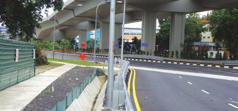
[5]

After establishing the baseline conditions, impact               during the tender stage, as they can better appreciate the
assessments will be conducted. For instance, in the aspect       site challenges and ensure that all mitigation measures that
of noise, simulations will be conducted to predict the noise     are needed have been planned for and factored into the
levels on sensitive receptors during the actual work across      costs. This prevents the situation where contractors are
the different construction phases (e.g. site clearance,          caught by surprise and resulting in higher mitigation costs.
excavation, piling, reinstatement). Contours representing        Apart from costs savings brought about by early planning,
the predicted range of noise levels during actual                disruption to projects’ timeline can also be avoided. Stop-
construction works will then be presented (Figure 2).            work orders and fines from regulatory agencies (e.g. NEA
With these simulations, sensitive receptors that may be          and PUB) can be prevented with proper environmental
significantly affected by our works can be easily identified     management. This reduces the amount of feedbacks
before construction works commences.                             received by our projects and eliminates the need for
                                                                 intervention by enforcement agencies.

                                                                 Aside from having a better downstream management
                                                                 of environmental impacts, an EIA also demonstrates
                                                                 to concerned stakeholders that LTA had invested due
                                                                 consideration to mitigate impacts and is exceptionally
                                                                 crucial in developing harmonious relations with concerned
                                                                 stakeholders. Through undertaking of EIA, an objective
                                                                 study can be conducted to gain an early understanding of
                                                                 a project’s potential impacts and benefits. The public would
                                                                 also be assured that no disruptive developments will be
                                                                 carried out before a comprehensive study is conducted.

                                                                 MOVING FORWARD – ENVIRONMENTAL IMPACT
                                                                 WORKSHOP AND REGISTER

                                                                 A new initiative will be implemented starting from TEL Civil
              Figure 2: Noise simulation contours                Package 5 & 6. To ensure that all environmental impacts
                reflecting predicted noise levels                are duly identified, properly cascaded and mitigated in the
                                                                 various phases of a project, contractors will be required to
With this understanding of potential impacts brought about       organise an environmental impact workshop within the first
by our projects, design changes could be incorporated            2 months upon the award of Contract to update and discuss
through the change of construction methods or through the        what will be implemented in response to the impacts and
identification of effective mitigation measures to reduce the    mitigation measures identified in the EIA report. These
impact on surrounding sensitive receptors. For instance,         workshops are not new and similar workshops had been
noise barriers of suitable height and acoustic qualities         carried out for managing noise in TEL Civil Package 3.
can be designed and specified upstream prior to the              This will result in the alignment of all stakeholders and give
commencement of construction (Figure 3).                         assurance that proactive measures are taken to address
                                                                 the issues identified in the EIA, instead of reacting to it
                                                                 when the situation arises during construction phase.

                                                                 CONCLUSION

                                                                 As compared to other developed countries, Singapore may
                                                                 be relatively new in the field of EIA. However, as the biggest
                                                                 developer in Singapore, LTA is exercising its due diligence
                                                                 in this area of study and looking to build an EIA framework
                                                                 that would make the process structured, standardised and
                                                                 systematic across all projects. As projects continue to roll
                                                                 out, LTA has moved in tandem, balancing the expectations
                                                                 of stakeholders and the needs of sensitive receivers, so
                                                                 that our projects can be delivered on time with minimum
                                                                 impact on the environment.

   Figure 3: Erection of 10m noise barriers on the side facing
                    noise sensitive receptors
                                                                                                                Lim Yiling
IMPORTANCE OF EIA IN OUR WORKS                                                               Deputy Environmental Manager
                                                                                                            Safety Division
As seen in the previous section, the use of EIA ensures that
the site condition is made known before actual construction
work commences. This is especially beneficial to contractors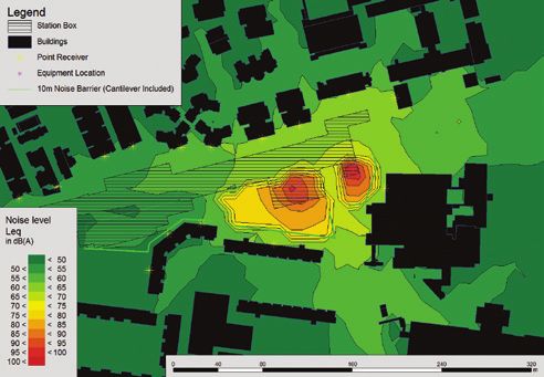
Temperature regulating mechanisms
[6]        and heat related disorders
           at CONSTRUCTION WORK SITES

INTRODUCTION                                                      An example would be, considering the temperature in
                                                                  the external environment is above the body’s set point,
Singapore, being one degree north from the equator,               say 38oC. Firstly, the skin (Receptor) sensed a raise in
the atmospheric temperature that one can experience is            temperature and the activated nerve cells sends information
generally hot and humid. The National Environment Agency          to the hypothalamus (Control Centre). The hypothalamus
has predicted based on weather statistics over the past           decides on the response and sends nerve impulses to the
decades that the highest temperature can measure up to            sweat glands (Effector) to increase their secretions. As the
35oC1. With varying environmental conditions that can last        secretions evaporate from the skin, it produces a cooling
throughout the day, the human body generally is able to           effect, and the body temperature drops to below 37oC. This
adapt to the changes.                                             signal is then feedback to the Control centre, which will
                                                                  cut off the corrective measure when the desired change is
However, when the human body fails to regulate the                achieved. Other forms of response which the hypothalamus
exposure to hot weather, the person can easily succumb to         may activate include dilation of the blood vessels and
heat related disorder that can injure or kill.                    relaxation of muscles attached to the hair follicles.

This article aims to highlight how the human body copes           TYPES OF HEAT RELATED DISORDERS
with high temperatures, the various types of heat related
disorders and preventive measures to be taken.                    Heat Cramps

HOMEOSTASIS                                                       Heat cramps can happen after hours of work in a hot
                                                                  environment. Loss of bodily fluid and the inadequate
Homeostasis is where the body regulates its functions to          replacement of salt are usually associated with the cause
maintain internal consistency while adjusting to conditions.      for heat cramps. Symptoms of heat cramps include painful
Homeostasis is maintained through negative feedback               muscle tightness on arms, abdomen, legs, and its onset
mechanisms, and its relation to regulate body temperature         can be brief or intermittent. One can prevent heat cramps
is elaborated in the following paragraphs below.                  by resting, drinking water or electrolyte fluids (e.g. isotonic
                                                                  “sports drinks”) adequately.
Negative Feedback Mechanisms
                                                                  Heat Exhaustion
Negative feedback happens when there is a need to change
its variable back to ideal state. This response will be turned    When a person has been exposed to high temperatures
off only when the normal value has been reached.                  over a prolonged period of time, he can be prone to heat
                                                                  exhaustion, as the person’s perspiration cannot dissipate
Homeostatic mechanisms have three components. They                the heat generated within the body. This result because of
are as illustrated:                                               salt and water lost over time, and dehydration occurs. The
                                                                  common signs and symptoms include profuse sweating,
                                                                  rapid heartbeat, dizziness, fatigue, nausea, vomiting, pale
                                                                  and hot skin. If anyone is experiencing signs and symptoms
                                                                  of heat exhaustion, bring the person to rest in supine position
                                                                  in a cool and shady area quickly, and remove extra layers
                                                                  of clothing. Apply cooling measures such as fanning, and
                                                                  provide the person with water or electrolyte fluids. Call 995 if
                                                                  emergency aid is required, or if the person does not recover.

              Figure 1: Homeostasis maintained
              by negative feedback mechanisms

A Receptor is a component that monitors changes in the
internal or external environment, and sends information to                     Figure 2: Treatment for heat exhaustion
the control centre. For example, heat is sensed at body’s
outer surface.                                                    Heat Syncope

A Control centre determines the range that is normal of           Heat syncope is associated with the dilation of blood
a factor. The control centre receives information from            vessels, which can cause the blood pressure to fall. This
the receptors and selects an appropriate response. In             usually occurs with prolonged standing or sudden rising
regulating body temperature, the control centre is located        from a sitting or lying position. As a result, less blood
in the brain.                                                     flows to the brain, and fainting or dizziness occurs. Other
                                                                  signs and symptoms include light headedness, or a loss of
An Effector is a component that carries out the selected          consciousness. Steps to treat heat syncope are similar to
response. In this context, it is the sweat gland.                 the treatment for heat exhaustion.

1. Source: Workplace Safety and Health Council Bulletin, Preventing Heat Stress at Work
2. Source: Workplace Safety and Health Guidelines, Managing Heat Stress in the Workplace
[7]

Heat Stroke                                                          upon arrival. Instead, the worker can undergo a 14 day
                                                                     heat acclimatisation program2. He can be acclimatised by
Heat stroke is the most severe form of heat related disorder.        gradually increasing his exposure to heat and workload over
It is also a form of hyperthermia, where the mechanism for           a 2 weeks period. Figure 4 illustrates a gradual increase in
lowering higher than normal body temperature fails. Being            exposure to heat over a period of 7 days.
considered a medical emergency, death will occur if the
person is not promptly or properly treated. Heat stroke can
also occur as a progression from the milder forms of heat                                              9

                                                                          Hours worked under the sun
related disorders. Symptoms can develop quickly when a                                                 8
                                                                                                       7
person is in a hot and humid environment, and physically                                               6

exerting himself. There are distinct signs and symptoms for                                            5

persons suffering from heat stroke, and they include core                                              4
                                                                                                       3
body temperature above 40oC, sweating has stopped, and                                                 2

skin feels hot and dry. The other signs and symptoms are                                               1                                                             11am to 3pm*

hallucination, confusion, disorientation, seizures, and rapid                                          0
                                                                                                             Day 1   Day 2   Day 3   Day 4   Day 5   Day 6   Day 7
                                                                                                                                                                     8am to 11am;
                                                                                                                                                                     3pm to 5pm

heartbeat.                                                                                                                     Day of work

It is very important to render first aid treatment to person         *Assuming that lunch hour is from noon to 1pm and that there are
suffering from heat stroke immediately. Steps include,               regular rest breaks
bringing the person to a cool shady area and fan him,
remove any unnecessary clothing, apply cool water to his                                                   Figure 4: Example of acclimatisation schedule2
skin, place ice packs under his armpits and groin area, and
call 995 immediately.                                                Adequate Water Intake

                                                                     One can keep himself hydrated by drinking water frequently.
                                                                     Supervisors can play an important role by encouraging their
                                                                     staff to quench their thirst all the time. Workers should also
                                                                     avoid the excessive intake of coffee and alcohol.

                                                                     Work Scheduling

                                                                     Whenever possible, avoid heavy physical work during the
                                                                     hottest part of the day (11am – 3pm). Alternating work and
                                                                     rest period, for example, every 5 minutes rest for every 25
           Figure 3: An emergency drill conducted on site            minutes of work, should be adopted under moderately hot
                 to educate workers on heat stoke
                                                                     conditions2.
RISK FACTORS                                                         Engineering Controls
Risk factors which can predispose a person to risk of heat           Provision of fans can increase general ventilation of the
related disorders are:                                               physical environment. Provision of Local Exhaust Ventilation
                                                                     to draw heat from high heat production areas can also help.
Susceptible Individuals

These include persons having poor general health, alcohol            Shaded Areas for Work and Rests
abuse, physical exhaustion, dehydration, or ill health.              Temporary shelters should be provided for workers who will
                                                                     spend a significant amount of time under the sun.
Clothing

Wearing excess clothing that prevents sweat from                     Clothing and Training
evaporating easily.                                                  Persons working in hot climate should wear light coloured
                                                                     and loose fitting clothing, and be educated on how heat
Unacclimatised Persons                                               related disorders can impact them.
Persons coming from countries of cooler climates, or have
little or no experience of working under the heat.                   CONCLUSION

                                                                     Our human body is designed to cope with certain amounts
PREVENTIVE MEASURES                                                  of heat through regulation of our body functions. However,
Consult a Doctor                                                     due to occupational demands, physical needs can be
                                                                     neglected and health is compromised. With awareness
Persons feeling unwell or exhibiting symptoms of ill health should   and effective mitigating measures, heat related disorders
seek medical attention prior to the commencement of work.            are preventable.

Acclimatisation

Under the Workplace Safety and Health Guidelines, a
person who is not used to working in a hot climate may take
                                                                                                                                                Liu Weng Keong, Ian
up to 2 weeks to be accustomed to the heat and workload.
                                                                                                                                 Assistant Safety and Health Manager
A new worker, especially for those coming from countries
                                                                                                                                                       Safety Division
of cooler climates, should not start working at full workload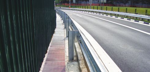
[8]        managinG drainage at WORK ZONE

INTRODUCTION                                                        mid-tangent section of the reverse curve where there is no
                                                                    crossfall does not coincide with the low point of the vertical
Roadside drain is an important feature along a carriageway          profile of the carriageway to avoid water ponding.
to ensure that the surface runoff can be adequately
discharged to minimise water ponding or flooding. Apart                                                   Crossfall
from the drainage capacity, there are other issues that
must be considered to ensure that the drain will not create
a hazard for road users. This article will discuss the various
considerations for the proper provision of a roadside drain
in the implementation of temporary road works.

a) Alignment & cross-section details
                                                                                              Crossfall
At the design stage, adequate space on the sidetable and
centre median, where necessary, have to be catered for
to accommodate the drains and this has to be properly
coordinated with the provision of other roadside features
such as footpath, street lighting, signs, safety barrier, etc.          Figure 3: Schematic illustration of a reverse curve with the
                                                                    provision of the crossfall and roadside drain along the inner radius
                                                                                              of the road bend.
           Site Hoarding       Light Pole
                                                                    If a road bend has to be introduced along a multi-lane
                                                                    carriageway, the impact on the road level along the existing
                                   Safety Barrier                   sidetable can be minimised by providing a carriageway with
                                                                    a split level along the centre divider with the use of a proper
                                                                    cast-in-situ safety barrier and the provision of a drain along
              Footpath                         Drainage inlet       the centre median.

                           Roadside drain
                                                                                  Crossfall

 Figure 1: Adequate width along the roadside has to be catered
   for to accommodate drains as well other roadside features.
                                                                                                                      Crossfall
Based on LTA Design Criteria, for a straight carriageway
section, a desirable minimum crossfall of 1 in 30 and a
minimum longitudinal gradient of 0.4% are required to
facilitate surface water drainage to the roadside drains.                Figure 4: Provision of drainage along the centre median
                                                                                      with a split-level carriageway.

                                                                    b) Proper provision of a roadside drain

                                                                    Where a precast concrete safety barrier is used, proper
                                                                    drainage inlets have to be provided between the safety
                                                                    barrier and carriageway to ensure that the surface runoff
                                                                    can be properly collected and discharged.

 Figure 2: Crossfall and longitudinal gradient are required along
          the carriageway to channel the surface runoff
                      to the roadside drains.

For road diversions, it is quite common that a reverse curve
is used especially at the interface between the existing
and diverted carriageway. A reverse curve is where the
road deflects in the opposite direction after the initial road
                                                                       Figure 5: The precast concrete safety barrier segments have
bend. Along the reverse curve, the crossfall and drainage            been disconnected to create gaps to allow surface runoff to flow
have to be provided accordingly along the inner radius              towards the roadside drain. However, while this may address the
of the road bend (Figure 3). Adverse crossfall happens               drainage issue, the precast concrete safety barrier will no longer
when the direction of the crossfall slopes towards the                be able to serve its function as a safety barrier and will create
outer radius of the road bend. This should be avoided as                              undue roadside safety issues.
it will pose stability problems especially for motorcyclists,
load-carrying vehicles as well as other vehicles with a high
centre of gravity. Care should be taken to ensure that the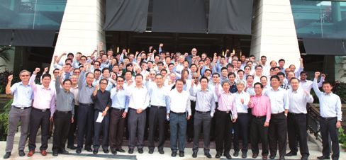
[9]

         Temporary drain                                                 c) Provision of a proper drainage inlet
         within work site.
                                                                         A proper drainage inlet based on the specifications in
                                                                         LTA design standard has to be provided to minimise any
                                                                         potential risk to vulnerable road users such as pedestrians,
                                                                         pedal-cyclists and motorcyclists.
                                   Inappropriate arrangement
                                   to allow surface runoff
                                   to flow through the
                                   gaps below the concrete
                                   barrier.                                                                                Drain cover with
                                                                                                                           wide open gaps.
                    Footpath

Figure 6: Where a footpath is located behind the precast concrete                       Opening for drainage
                                                                                        inlet along footpath.
   safety barrier, the surface runoff should not be allowed to flow
 through the gaps below the precast concrete barrier and across
  the footpath as this will result in inconvenience for pedestrians
 and slippery condition along the footpath.A proper drainage inlet
  could be provided in front of the precast concrete safety barrier
          to channel the surface runoff below the footpath               Figure 9: Improper surface openings for drainage inlets along the
                      and into the roadside drain.                             footpath will create a tripping hazard for pedestrians.

If the temporary road works involve the use of non-rigid
safety barrier such as w-beam guardrail or unrestrained
temporary safety barriers such as water-filled safety barrier,
steel or precast concrete safety barrier, adequate lateral
offset has to be provided between the safety barrier and
open roadside drain to cater for the deflection of the safety
barrier when it is impacted by a vehicle.

                                                                                                     Wide gap

                                                                         Figure 10: Improper construction of drainage inlets with wide gaps
                                                                          along the carriageway could pose stability problems for cyclists.

   Figure 7: If the w-beam guardrail is impacted, the impacting
vehicle is likely to crash into the open drain as the w-beam will not
be able to cater for the vehicular impact. This is due to insufficient
   space behind the guardrail for it to deflect in order to safely
   contain and redirect the vehicle back onto the carriageway.

If the required clear zone could not be provided due to site
constraints, the roadside drain has to be shifted further
away from the carriageway or covered-up to provide the
required clear and traversable area behind the safety                     Figure 11: The current design standards require the provision of
barrier to cater for the dynamic deflection. Alternatively,              drainage inlets with gratings that are perpendicular to the direction
a fully restrained temporary safety barrier can be used by                      of travel and smaller gaps in-between the gratings.
anchoring the safety barrier onto the carriageway.
                                                                         CONCLUSION

                                                                         There are many challenges faced in the implementation of
                                                                         the temporary road works to facilitate the timely completion
                                                                         of road and rail projects. The temporary traffic scheme,
                                                                         including the provision of roadside features such as drains
                                                                         and drainage inlets, has to be properly designed for and in
                                                                         compliance with design requirements to ensure that the road
                                                                         system serves its intended function, without compromising
                                                                         on the safety of road users and work site personnel.

Figure 8: Use of a drain covered with vehicular grating behind the                                                     Rozmand Jamaludin
w-beam guardrail which will also allow for the dynamic deflection                                               Road System Safety Manager
            of the w-beam guardrail when impacted.                                                                           Safety Division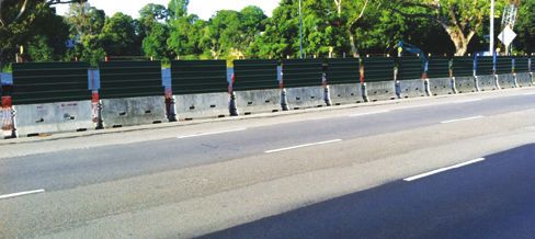
sAFETY CONSIDERATIONS IN NORTH-EAST
[10] LINE ADDITIONAL TRAINS PROJECT

Introduction                                                        Detrainment Door Overview

The North-East Line (NEL), operated by Singapore Bus                The Detrainment Door is fitted at both ends of the new trains
Services Transit (SBST), is a fully automated and driverless        and provides an exit for passengers to disembark to the
rail system powered by a 1500 V DC (Direct Current)                 track level when deployed during emergencies. Compared
Overhead Catenary System. NEL connects the heartlands               with the existing NEL trains, the main differences between
such as Punggol and Sengkang in the North-East region of            the Detrainment Doors of the new trains are:
Singapore, passing through the Central Business District at
Douby Ghaut, and terminates at Harbourfront.                             New Trains (C751C)            Existing Trains (C751A)
With six carriages per train, the NEL currently has a fleet                 Flip up design                  Flip down design
of 25 trains. To cater to an expected increase in passenger            Activation via a handle        Activation via push button
traffic, 18 additional new trains will be added to the existing       Provision of a windscreen               Solid panel
fleet to enhance the rail capacity. These additional trains
are supplied under Contract 751C.                                   Table 1: Difference between the new and existing NEL trains

C751C Train for North-East Line                                     The Detrainment Door of new trains opens upwards and
                                                                    has only 1 leaf. Its operation is purely mechanical, and
Contract 751C has been awarded to Alstom Transport                  there is no need for any power source for deployment or
S.A. / Alstom Transport (S) Pte Ltd Consortium for the              stowage as illustrated in Figure 1.
procurement of the additional new NEL trains. These
additional new trains are designed for driverless operation
in both the depot stabling areas and on the revenue line,
including the sidings with the provision of manual operation
control. In addition, they are also fully compatible with
the existing NEL system and the fleet of trains in terms
of functionality, system interface operability, performance,
coupling capabilities and other operating systems.

The immediate questions in mind for the additional new
NEL trains would be; how different are they from the
existing ones? Are there disparities in safety standards?
As technology advances, there will inevitably be variations
between the new trains and its predecessors. In fact, with
technological advancements and its range of new features,
passenger safety is enhanced.

These additional new trains have been carefully evaluated
to ensure that their subsystems are similar to that of their
existing counterparts. The new trains feature a slew of
new improvements, which includes the Dynamic Route
Map Display (DRMD), frangible strips, Semi-permanent
Coupler and Detrainment Doors. This article will focus
on the Detrainment Doors, deformation tube in the Semi-
permanent Coupler and the frangible strip.

Design Consideration for Detrainment Door
                                                                           Figure 1: Deployment of C751C Detrainment Door
The key consideration in the design of the Detrainment
Door is on its deployment in times of need. The Detrainment
Door will deploy only when it is safe for the commuters to
disembark. This design consideration is aligned with the
original design principle, which is paramount to passenger
safety.

The design of the Detrainment Door needs to maintain the
basic principle of sending an alarm to the Operations Control
Centre (OCC) in the event of a physical activation of the
door. Upon the request for detrainment made by passenger
via the Detrainment Door handle, the Detrainment Door
will open automatically after the Automatic Train Protection
System (ATP) signalling system confirms that the train is
stationary. This operating principle of the existing train’s
Detrainment Doors will act as the basis for the design of the            Figure 2: 3D schematic of the C751C Detrainment Door
Detrainment Door for the new NEL trains.

1. Semi-permanent Coupler is a mechanism which connects 6 separate train cars to form one 6-car train set
[11]
The main advantages of the new trains Detrainment Doors Provision of Frangible Strips
are:
The new NEL trains are fitted with frangible strips which
• Manufactured using lightweight material minimises the stepping distance between the train and the
• Modular design with ramp and structure being one platform edge. The frangible strip (outlined in red) is shown
single assembly which allows easy installation on in Figure 6.
the vehicle
• Provision of a windscreen for enhanced visibility
• Ease of deployment; passenger can deploy simply
by following instructions provided. It takes not more
than 30 seconds to deploy the Detrainment Door
and stowing can be achieved in 10 minutes
• Occupies minimum cabin space, with a simple
interface with vehicle.
Deformation tube for Semi-Permanent
Coupler
Another safety enhancement to the new NEL trains is
the provision of a deformation tube in the second half of
the Semi-permanent Coupler1. The deformation tube
is a sacrificial device having a maximum buff stroke of
220mm and a maximum compressive force of 1000kN.
This translates to a maximum dynamic absorption capacity Figure 6: Reduced platform gap due to the use of frangible strips
of 220kJ. This energy absorption component helps keep
forces and accelerations at acceptable levels and prevent The provision of the frangible strip for the new NEL trains
unnecessary damage to car bodies. Figures 3 and 4 reduces the likelihood of a passenger’s foot being trapped
provide an illustration of the Semi-permanent Coupler and between the station platform and the train.
deformation tube.
Conclusion
The new trains are fully compatible with the NEL system
and existing NEL train fleet in terms of functionality, system
interface operability, performance and coupling capabilities.
In general, the design of the new NEL trains is compliant
with all the applicable design safety principles.
On a concluding note, safety is an integral part of design.
Figure 3: Second half of Semi-permanent Coupler assembly Therefore, it is paramount that the design of the new
trains is managed with due diligence. Detailed analysis
on the design differences between the existing trains and
the new trains were conducted to identify and mitigate
any new hazards arising from design differences. Hazard
management activities have also ensured that all hazard
mitigating measures identified for the existing trains are
also implemented in the new trains. With the compliance of
safety management activities specified within the Systems
Figure 4: Coupler shank with deformation tube Assurance Plan, the additional new trains for NEL project
was able to demonstrate the achievement of the level of
The basic principle in the operation of a deformation tube is safety specified at the Design Stage.
to dissipate energy through the extrusion (widening of the
diameter) of a cylindrical tube (depicted in yellow in Figure
5 below).
Regina Ng
Manager, Systems Assurance & Integration
Systems & Rail Assets Group
Lee Shu Chuan
Assistant Rapid Transit System Safety Manager
Safety Division
Figure 5: Operating principle of a deformation tube[12] EDITORIAL pAGE
LTA 33rd Safety Workshop Four presentations were delivered during the Safety
Workshop. The topics presented were:
The 33rd Safety Workshop organised by Safety Division
was held on the 29th June 2015 at HSO Auditorium. It 1. Sharing on LTA Annual Safety & Environmental
was attended by more than 100 officers from Rail, Road Performance in year 2014 by Mr. Cheong Zhi Hao,
Projects and Engineering Groups. The Workshop served Kenneth, Deputy Safety & Health Manager; and Ms.
as a regular forum for LTA staff to share their technical / Low Shi Mei, Assistant Environmental Manager
practical experiences and challenges faced by them in the
delivery of their projects. It also provides a platform for LTA 2.
Safety Challenges in NEL Depot Stabling Track
senior management to interact with the site staff. Expansion Works by Mr. Tan Hong Kwang, Melvin,
Acting Project Manager
Figure 1:
3. Safety Considerations of Closing the Temporary Staging
Mr. Cheong Zhi Hao, Kenneth
Deputy Safety Area’s roof opening above a LIVE track by Mr. Chua
& Health Manager Chee Meng, Principal Engineering Officer
4. Updates on MOM’s Operations and the Demerit Point
System (DPS) by Mr. Tong Tee Hui, Senior Assistant
Director, Occupational Safety and Health Inspectorate,
Ministry of Manpower
Figure 2: Figure 4:
Ms. Low Shi Mei Mr. Chua Chee Meng
Assistant Environmental Principal Engineering Officer
Manager
Figure 3: Figure 5:
Mr. Tan Hong Kwang, Melvin Mr. Tong Tee Hui
Acting Project Manager Guest Speaker
Senior Assistant Director
Ministry of Manpower
Editorial Committee Contributions or feedback to:
Land Transport Authority
Advisor Safety Division
Corporate Safety Committee No. 1, Hampshire Road, Blk 5, Level 4, Singapore 219428
Tel: (65) 6295 7392 Fax: (65) 6396 1188
Editors
Email address: ian_LIU@lta.gov.sg
Phoa Hock Lye, Patrick
Liu Weng Keong, Ian
Safety News is also available online at
Lee Yu Qi, Jocelyn
http://www.lta.gov.sg/content/ltaweb/en/industry-matters/safety-and-
Circulation Officer health-and-environment/construction-safety-and-environment/safety-
Zhuo Shumei news.html
Writers
Kevin Seet or scan
Lim Yiling
Liu Weng Keong, Ian
Rozmand Jamaludin
Regina Ng
Lee Shu ChuanYou can also read