Selectively controlled magnetic microrobots with opposing helices - DAMTP
←
→
Page content transcription
If your browser does not render page correctly, please read the page content below
Applied Physics Letters                                                                         ARTICLE             scitation.org/journal/apl

    Selectively controlled magnetic microrobots
    with opposing helices
    Cite as: Appl. Phys. Lett. 116, 134101 (2020);doi: 10.1063/1.5143007
    Submitted: 20 December 2019 . Accepted: 15 March 2020 .
    Published Online: 31 March 2020

    Joshua Giltinan,1             Panayiota Katsamba,2         Wendong Wang,1          Eric Lauga,3         and Metin Sitti1,4,a)

    AFFILIATIONS
    1
        Physical Intelligence Department, Max Planck Institute for Intelligent Systems, Stuttgart 70569, Germany
    2
        School of Mathematics, University of Birmingham, Edgbaston, Birmingham B15 2TT, United Kingdom
    3
        Department of Applied Mathematics and Theoretical Physics, University of Cambridge, Cambridge CB3 0WA, United Kingdom
    4
        School of Medicine and School of Engineering, Koç University, 34450 Istanbul, Turkey

    a)
         Author to whom correspondence should be addressed: sitti@is.mpg.de

    ABSTRACT
    Magnetic microrobots that swim through liquid media are of interest for minimally invasive medical procedures, bioengineering, and
    manufacturing. Many of the envisaged applications, such as micromanipulation and targeted cargo delivery, necessitate the use and adequate
    control of multiple microrobots, which will increase the velocity, robustness, and efficacy of a procedure. While various methods involving
    heterogeneous geometries, magnetic properties, and surface chemistries have been proposed to enhance independent control, the main
    challenge has been that the motion between all microswimmers remains coupled through the global control signal of the magnetic field.
    Katsamba and Lauga [Phys. Rev. Appl. 5, 064019 (2016)] proposed transchiral microrobots, a theoretical design with magnetized spirals of
    opposite handedness. The competition between the spirals can be tuned to give an intrinsic nonlinearity that each device can function only
    within a given band of frequencies. This allows individual microrobots to be selectively controlled by varying the frequency of the rotating
    magnetic field. Here, we present the experimental realization and characterization of transchiral micromotors composed of independently
    driven magnetic helices. We show a swimming micromotor that yields negligible net motion until a critical frequency is reached and a
    micromotor that changes its translation direction as a function of the frequency of the rotating magnetic field. This work demonstrates a
    crucial step toward completely decoupled and addressable swimming magnetic microrobots.
    Published under license by AIP Publishing. https://doi.org/10.1063/1.5143007

          Microrobots, untethered mobile machines capable of navigating       on the swimmer, yielding a propulsive force that scales more favorably
    and manipulating in a sub-millimeter environment, are envisioned as       than magnetic gradient pulling.21
    a technology that will revolutionize healthcare, bioengineering, and            In two dimensions (2D), specialized surfaces are able to restrict the
    manufacturing.1–5 For these applications, their manipulation in fluidic   motion of microrobots, such that their response to the global control sig-
    environments is of great interest for both applications and scientific    nal can be individualized.12,22,23 However, these methodologies are
    studies. The control of multiple microrobots could increase their effi-   unable to be adapted for a workspace far from any boundaries. In three
    cacy in various tasks, such as micromanipulation6 and cargo delivery.7    dimensions (3D), helical magnetic microrobots typically swim by rotat-
    Thus, it is advantageous to study methodologies to control multiple       ing the magnetic field perpendicular to the desired axis of propulsion.
    magnetic microrobots.8–12 As microrobots become smaller, nonrecip-        An anisotropy in the fluid drag yields a forward force as a result of the
    rocal swimming becomes a scalable mode of propulsion at low               net viscous drag on the structure. In a given frequency range, this motion
    Reynolds numbers.13 Generating nonreciprocal motion with microro-         leads to a stable forward propulsive force.24,25 An example response,
    bots in low Reynolds number environments has been a topic of recent       called the step-out profile, is illustrated in Fig. 1(a).26 If the handedness
    research; helical structures,14 swimming sheets,15–17 undulatory          of the spiral is reversed, the swimmer will have a negative propulsion in
    robots,18 and irregularly shaped clusters19,20 in a time-varying mag-     the same rotating magnetic field, as illustrated in Fig. 1(b). In each exam-
    netic field have been proposed as fluidic propulsion solutions.           ple, the swimming velocity linearly increases with the frequency until a
    Magnetic fields are of interest due to their long range and ability to    critical “step-out” frequency is reached. This is the frequency where fluid
    safely penetrate tissues.5 The magnetic field induces a magnetic torque   resistive torque exceeds the maximum possible magnetic torque, and

Appl. Phys. Lett. 116, 134101 (2020); doi: 10.1063/1.5143007                                                                                   116, 134101-1
Published under license by AIP Publishing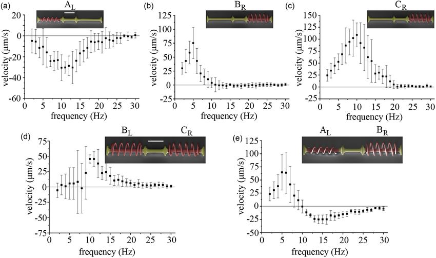
Applied Physics Letters                                                                                                 ARTICLE             scitation.org/journal/apl

                                                                                                             As the velocity profile of a single magnetized helix lacks the cutoff
                                                                                                      at low frequencies, Katsamba and Lauga proposed to couple two heli-
                                                                                                      ces of opposite handedness in what is called the transchiral helical
                                                                                                      micromotor to achieve a banded velocity profile.36 This interval of
                                                                                                      actuating frequencies, an effective frequency band, would allow selec-
                                                                                                      tive control over multiple micromotors. The helices are coupled such
                                                                                                      that they can freely rotate about the axial rod but are constrained to
                                                                                                      move at the same velocity, pushing or pulling each other in the
                                                                                                      opposite direction. The geometric and magnetic properties of the two
                                                                                                      helices can be selected to tune this force balance to give rise to the
                                                                                                      required banded velocity profile. An example is illustrated in Fig. 1(c).
                                                                                                      Here, before any of the two helices of the transchiral motor step out,
                                                                                                      the force balance is such that the motor is stationary. After the first
                                                                                                      step-out frequency, the helix that has not stepped out dominates, with
                                                                                                      a monotonically increasing velocity profile, until it also steps out, after
                                                                                                      which the velocity decreases to zero as the frequency is increased
                                                                                                      further. The force balance in a transchiral motor can also be tuned to
                                                                                                      give a velocity profile with positive and negative values in different fre-
                                                                                                      quency ranges, as illustrated in Fig. 1(d). This allows for reversal of the
     FIG. 1. Transchiral motor concept. Illustrations of each motor are given above the               direction of motion by changing the actuating frequency. With differ-
     respective plots with right and left handedness marked “R” and “L.” (a) The characteristic       ent micromotors having distinct non-overlapping effective frequency
     velocity–frequency response of a magnetic chiral swimmer. The velocity is linearly pro-
     portional to the rotation frequency of the magnetic field, ~  B, until the step-out frequency
                                                                                                      bands, one can choose which to operate by tuning the magnetic field
     Xs. (b) When the handedness is opposite, in the same rotating magnetic field, the spiral         frequency appropriately. If one wishes to combine both features of
     will propel in the opposite direction. Coupling the translation forces of two helices results    selective control via the banded velocity profile and reversal of motion,
     in nonlinear behavior before all spirals reach their step-out frequencies. (c) The velocity–-    then at least three helices would be required.36
     frequency response of two helices with opposing handedness but otherwise identical                      Here, we present the characterization of transchiral micromotors
     geometry and magnetic strength. Until the magnetically weaker helix steps out, there is          composed of independently driven magnetic helices. In order to couple
     no net translation. After the first spiral steps out, Xs1 , the velocity nonlinearly increases
     until the second spiral steps out at frequency Xs2. (d) The velocity–frequency response          the translation of the spirals but not their rotation, we used an axial rod
     of two helices with heterogeneous geometry, one has a spiral diameter of 100 lm and              that passes through the central axis of the helices and has disk-shaped
     the other has a diameter of 200 lm. A spiral with a larger radius has a higher velocity,         tapers that prevent the helices from exiting the structure. This allows
     but a lower step-out frequency, Xs3 , than a spiral with a smaller radius, Xs4 .                 freedom of rotation between the helices. The helices push against the
                                                                                                      tapers and transmit their propulsive force to the axial rod, thereby
    thus it is a function of fluid viscosity, helix drag coefficient, magnetic                        resulting in the push/pull relation explained by Katsamba and Lauga.36
    moment of the helix, and magnetic field magnitude. After this fre-                                Without rotational coupling, the spirals respond to a rotating magnetic
    quency, the velocity nonlinearly decreases to zero. Assuming that the                             field as if they were not in the presence of other structures. As our
    viscosity of the fluid is constant, decreasing the drag on the swimmer by                         Reynolds numbers are on the order of 10!2, we assume that the spirals
    altering its surface chemistry would increase its step-out frequency.                             operate in the Stokes flow regime, and the force exerted on the passive
    Wang et al. exploited this by changing the surface chemistry on the out-                          frame by each spiral will be proportional to the swimming velocity of
    side of the spiral using various thiol and thioether-based compounds. By                          the spiral. We fabricate and characterize two configurations of transchi-
    driving more hydrophobic spirals at higher frequencies, separate groups                           ral motors. The first configuration consists of two spirals that possess
    of spirals with otherwise homogeneous geometry could be controlled.27                             homogeneous geometry, opposite handedness, and differing magnetic
    As the constant of proportionality between forward velocity and mag-                              strengths. At low frequencies, the net propulsion should be zero, as
    netic field frequency is related to the geometric and magnetic properties                         illustrated in Fig. 1(c). The second configuration consists of two helices
    of the spiral, control schemes can exploit the different motion primitives                        with heterogeneous geometry, and the propulsion direction is depen-
    of swimmers to drive heterogeneous swimmers to unique locations.28–32                             dent on the rotation frequency, as illustrated in Fig. 1(d). The assump-
    Helical motors are also the smallest, mass-produced magnetic microro-                             tion of this working principle is that there is a continuous mechanical
    bots. Glancing-angle deposition (GLAD) is able to achieve helices on the                          contact between each spiral and the rod, such that each spiral is exerting
    nanometer scale,33 and independent control of these has been demon-                               a force on the rod that is completely in the direction of propulsion (the
    strated by exploiting their interactions with a nearby surface.34                                 long axis of the rod). Thus, by pushing against the tapered ends of
    However, swimming helical microrobots currently cannot exhibit two                                the rod, the two spirals are effectively pushing or pulling each other. If
    features. The first is a zero net translation response to a rotating mag-                         the spiral is not pushing perfectly in the direction of the long axis, a por-
    netic field. Control of heterogeneous swimming microrobots would ben-                             tion of the transmitted force could be perpendicular to the long axis of
    efit from banded frequency responses, where ideally there would be no                             the micromotor, which may lead to a variation in the resulting speed.
    net motion if the magnetic field was actuating outside of the frequency                                  Three species of helices were used as the mobile components of
    band. Second, reversible motion without changing the magnetic field                               the transchiral motors. Their geometry and results are summarized in
    rotation direction has currently only been demonstrated by randomly                               Table I. The second and third species possessed an additional half turn
    self-assembled non-helical magnetic propellers.35                                                 with a tapering diameter on both ends, to ensure that the spiral was

Appl. Phys. Lett. 116, 134101 (2020); doi: 10.1063/1.5143007                                                                                                           116, 134101-2
Published under license by AIP Publishing
Applied Physics Letters ARTICLE scitation.org/journal/apl
contained and would not exit the axial rod. As our micromotors have fabricating the micromotor where each spiral has its own cobalt thick-
an overall length of a few millimeters, the weight of the micromotors ness, the spiral with less material was also given a sacrificial cover that
and the axial rod cannot be overcome by the propulsion of the micro- was removed in between cobalt sputtering steps. The micromotors
motors. Thus, the micromotors are characterized while near the sur- were developed in propylene glycol monomethyl ether acetate
face of their environment. The rotation of the spirals induced by the (Sigma-Aldrich) and then rinsed with isopropyl alcohol. The sample
rotating magnetic field also contributes a rolling motion when near was sputter-coated with 30 nm-thick titanium (Leica EM ACE600),
the surface.21 We employ microfluidic channels to constrain the lateral 200 or 400 nm-thick cobalt (Kurt Lesker Nano 36), and then again
motion of the micromotors, such that the micromotors will only move with 30 nm-thick titanium. The sample was then coated with a layer of
along their long axis. The micromotor is, thus, bound by a 12 mm perfluorodecyltrichlorosilane (Sigma-Aldrich) by physical vapor depo-
long channel with a square cross section of 300 " 300 lm2. sition. The silane layer was approximated to be one molecular layer,
Before each set of experiments, the channels were rinsed with $ 2 nm. Small deviations in the deposition thicknesses due to equip-
ethanol and then sonicated for two minutes, which was repeated with ment or environmental changes can contribute to the variance in the
de-ionized water. The sample was dried and then treated with oxygen observed speed. The sacrificial structures around the spirals would be
plasma at a pressure of 0.2 mBar for two minutes. The channel was removed before use in an experiment. To magnetize the spirals, the
placed in a petri dish and filled with a mixture of 1% polysorbate 20 micromotor would be placed in an enclosed Gel-Box (Gel-Pak) and
and de-ionized water. In an experiment, we tested the clockwise and magnetized in a 1.8 T magnetic field. Cobalt yielded an intrinsic rema-
counterclockwise rotation directions of the magnetic field for ten sec- nent magnetization of $ 500 kA/m. Other magnetic materials, such as
onds each. Toward eliminating any possible preferred directionality paramagnetic iron oxide, could be utilized with a stronger magnetic
due to vibration or lithography artifacts, this process was repeated field. This ensured that the spirals would always be magnetized per-
three times. In the first, the entire workspace was rotated 180# , then pendicular to the long axis of the micromotor.
the transchiral motor was manually rotated 180# , and the workspace To properly quantify the behavior of individual spiral species,
was then rotated 180# again for the fourth run. For each ten second each was fabricated with the axial, tapered rod and no opposing helix.
run, a least squares linear fit was applied to the position of the micro- The quantitative results are given in Figs. 2(a)–2(c) for species (a)–(c),
motor, and this process yielded eight velocities for a given frequency. respectively, and summarized in Table I. The transchiral motor results
Some data points were manually removed if post-processing revealed are summarized in Table II. Figure 2(d) shows the experimental results
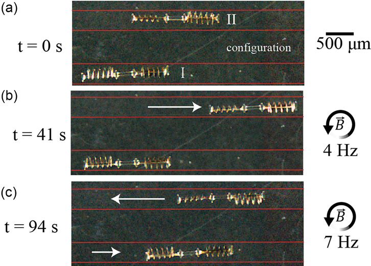
that the micromotor was unable to overcome static friction. of the case illustrated in Fig. 1(c). The helices used were species BL
Transchiral micromotors were fabricated using two-photon and CR . It was expected that there should be no net motion until
lithography in a Nanoscribe Photonic Professional GT using IP-S pho- species BL reached its step-out frequency, 5 Hz. However, between 5
toresist (Nanoscribe GmbH). In order to minimize fabrication errors, and 10 Hz large velocity variance was observed. The peak velocity,
special care was taken to make sure that the central rod structure was 46 lm/s, was observed at the step-out frequency of species CR , 10 Hz.
split at the larger portion (disk) that would anchor the structure to the The velocity nonlinearly decayed afterwards. It is important to note
substrate. To ensure that the spirals were not permanently attached to this is less than half of the peak velocity of spiral species CR , despite
the substrate or the center rod, 2 lm diameter support rods were the fact that there should be no translational contribution of spiral spe-
placed on the bottom of each spiral loop and connected to a base layer cies BL . The additional mass of the second spiral and fluid coupling of
that when sliced would be one polymerized layer, approximately the spirals could explain the reduction in peak velocity.
700 nm thick. The support cylinders were broken during the develop- The second transchiral motor behavior illustrated in Fig. 1(d)
ment process, allowing the spirals to rest on either the substrate or the shows the case of when the spirals do not have equal geometry, includ-
rod. Sacrificial structures were printed over the passive rod and disks, ing opposing handedness. The transchiral motor was fabricated with
preventing the deposition of metal onto these structures. When helix species AL and BR , Figs. 2(a) and 2(b). The results for both rota-
TABLE I. The properties of the individual spiral species used in physical tion directions are shown in Fig. 2(e). The helix from species AL has
experiments. an opposing handedness that yields propulsion in the negative direc-
tion. The peak velocities in the positive and negative directions corre-
Spiral spond to the step-out frequency of each respective helix, 5 and 11 Hz.
Spiral species Wire diameter Length diameter To provide a demonstration that this method could be used to
and handedness (lm) (lm) Turns (lm) independently actuate two micromotors in a single workspace, both
configurations were placed into two parallel separate microchannels.
AL 20 470 4.5 100
Their initial positions are shown in Fig. 3(a). The magnetic field was
BR;L 20 490 4.5 200
rotated initially at 4 Hz for 40 s. Configuration I had negligible net
CR 20 490 4.5 200 motion, while configuration II translated over one body length in the
Step-out positive x-axis. In the subsequent 54 s, configuration I moved in the
Spiral species Cobalt thickness frequency Maximum positive x-axis, and configuration II reversed the direction to propel in
and handedness (nm) (Hz) velocity (lm/s) the negative x direction.
The results from Fig. 2 show high variance in the forward velocity
AR 200 11 30 of the micromotors at each input frequency. While multiple runs were
BR;L 200 5 75 completed to ensure that there was no preferred directionality of the
CR 400 10 110 micromotor or microchannel, stochastic striction, vibration, or imper-
fections in the microstructures could result in a distribution of
Appl. Phys. Lett. 116, 134101 (2020); doi: 10.1063/1.5143007 116, 134101-3
Published under license by AIP PublishingApplied Physics Letters ARTICLE scitation.org/journal/apl
FIG. 2. Quantitative results of individual microspirals in axial rods and transchiral micromotors in a 2 mT rotating magnetic field. Multiple 10 second runs were made for a given
frequency and experimental conditions described in the text. Error bars indicate the standard deviation of the velocity of multiple runs. The insets for each plot show scanning
electron micrographs of the corresponding single contained spirals and transchiral motors. Species are indicated above the spirals. Red indicates the spirals and axial rod that
are coated in magnetic material. Yellow coloring indicates inert resin. Scale bars in (a) and (d) are 250 lm. (a) Single helix with a diameter of 100 lm. (b) Single helix with a
diameter of 200 lm. (c) Single helix with a diameter of 200 lm and double the magnetic material of the spiral used in (b). (d) Transchiral motor with two identical spirals with
opposing handedness and differing magnetic strengths. (e) Transchiral motor with heterogeneous spiral helices.
velocities. As the helices are always rotating, it is possible for them to be approximately 20% greater.10 The proximity of one helix to another
encounter friction on the tapering disks of the axial rod. If the disk was yields the possibility of fluid drag coupling since a rotating helix induces
too small, the spiral would not be contained. A larger disk would yield a rotational fluid flow, which then acts on the second helix, rotating it
greater drag and inertia on the micromotor. At a diameter approxi- and yielding a forward propulsion. The separation of micromotors is,
mately equal to that of the spiral, then the spiral may become hooked thus, facilitated by the axial rod as the induced fluid flow decays with
on to the circle and cease rotation. Vibration of the workspace was the square of the distance from the helix. However, additional separa-
kept minimal through relatively small magnetic field magnitudes. To tion comes with an additional structural mass and increases the overall
minimize striction, the micromotors were given a monolayer coating size of the motor, and thus, the separation distance is an important
of low surface energy fluorosilane, the microchannels were treated design parameter of transchiral motors.
with oxygen plasma to ensure a high energy surface that would The microchannel side walls prevent the rolling of the micro-
completely wet, and surfactant was added to the aqueous media. swimmer on the channel surface and remove the need of steering the
The proximity to the microchannel walls and axial rod induce
additional fluid drag on the micromotors.37 In general, these wall effects
are dependent on the cube of the distance to the wall and become signif-
icant within one body length, the diameter of the spiral, of the wall.38
Within a few micrometers of contact, the fluid drag can be expected to
TABLE II. The properties of the transchiral micromotor configurations used in physi-
cal experiments.
Rod
Transchiral diameter Disk diameter Spiral Expected
configuration (lm) (lm) combination behavior
I 45 155 BL þ CR No motion
until 5 Hz
FIG. 3. Transchiral micromotor addressability in a 2 mT rotating magnetic field. The
II 45 155 AL þ BR Reversing
microchannels are outlined in red, and motion is indicated by the white arrow. (a) Initial
direction positions with configuration designations. (b) After $ 40 s rotating at 4 Hz, configuration
between 5 I had no net motion and configuration II moved to the center. After an additional $ 55 s,
and 11 Hz rotating at 7 Hz has reversed the propulsion direction of configuration II and configura-
tion I has translated to the right. Multimedia view: https://doi.org/10.1063/1.5143007.1
Appl. Phys. Lett. 116, 134101 (2020); doi: 10.1063/1.5143007 116, 134101-4
Published under license by AIP PublishingApplied Physics Letters ARTICLE scitation.org/journal/apl
8
microswimmer during characterization. A single helical spiral is able D. R. Frutiger et al., “Small, fast, and under control: Wireless resonant mag-
to steer and reorient by a change in the direction of the rotating mag- netic micro-agents,” Int. J. Rob. Res. 29, 613–636 (2010).
9
J. Zhang, P. Jain, and E. Diller, “Independent control of two millimeter-scale
netic field, which induces a rigid body torque on the helix.21 Far from
soft-bodied magnetic robotic swimmers,” in IEEE International Conference on
a solid boundary, the transchiral motor can be steered similarly since Robotics and Automation (2016), pp. 1933–1938.
the entire microswimmer has a net magnetization, which can be used 10
E. Diller, J. Giltinan, and M. Sitti, “Independent control of multiple magnetic
to reorient the microswimmer. microrobots in three dimensions,” Int. J. Rob. Res. 32, 614–631 (2013).
11
This methodology theoretically allows an infinite number of spirals E. Diller et al., “Control of multiple heterogeneous magnetic microrobots in two
in one micromotor, and each could step out at a different frequency.36 12
dimensions on nonspecialized surfaces,” IEEE Trans. Rob. 28, 172–182 (2011).
C. Pawashe, S. Floyd, and M. Sitti, “Multiple magnetic microrobot control using
A special case of the three spiral micromotor is to yield no net motion
electrostatic anchoring,” Appl. Phys. Lett. 94, 164108 (2009).
before the first and after the third step-out frequencies. The spirals need 13
E. M. Purcell, “Life at low Reynolds number,” Am. J. Phys. 45, 3–11 (1977).
to be designed such that there is no net motion until the first spiral steps 14
L. Zhang et al., “Artificial bacterial flagella: Fabrication and magnetic control,”
out. In addition, the third spiral’s behavior after step-out must counter Appl. Phys. Lett. 94, 064107 (2009).
15
the other two spirals’ nonlinear decay. If these conditions are met, there E. Diller et al., “Continuously distributed magnetization profile for millimeter-
is only net motion in a specific frequency range. A workspace with mul- scale elastomeric undulatory swimming,” Appl. Phys. Lett. 104, 174101 (2014).
16
W. Hu et al., “Small-scale soft-bodied robot with multimodal locomotion,”
tiple micromotors with different frequency ranges can then indepen-
Nature 554, 81 (2018).
dently drive each motor with no net motion to the other. The size of the 17
G. Z. Lum et al., “Shape-programmable magnetic soft matter,” Proc. Natl.
micromotor is limited by physical scaling. The magnetic torque scales Acad. Sci. 113, E6007–E6015 (2016).
with the volume of the magnetic material, while friction scales with the 18
R. Dreyfus et al., “Microscopic artificial swimmers,” Nature 437, 862 (2005).
surface contact area and viscous drag scales with the length.39 19
P. J. Vach et al., “Selecting for function: Solution synthesis of magnetic nano-
Intrinsically stronger magnetic materials and more slippery coatings propellers,” Nano Lett. 13, 5373–5378 (2013).
20
would allow for a further decrease in the micromotor’s size. P. J. Vach et al., “Fast magnetic micropropellers with random shapes,” Nano
Lett. 15, 7064–7070 (2015).
In this Letter, we have presented the fabrication and experimental 21
J. J. Abbott et al., “How should microrobots swim?,” Int. J. Rob. Res. 28,
characterization of transchiral micromotors, swimming microrobots 1434–1447 (2009).
with two magnetic helical structures free to independently rotate. 22
B. R. Donald et al., “An untethered, electrostatic, globally controllable mems
Their translation forces are coupled through an axial tapered rod, micro-robot,” J. Microelectromech. Syst. 15, 1–15 (2006).
23
which restricts their forward motion. We showed two configurations, D. Cappelleri et al., “Towards mobile microrobot swarms for additive micro-
one which did not have a net propulsion until a critical frequency and manufacturing,” Int. J. Adv. Rob. Syst. 11, 150 (2014).
24
L. Zhang et al., “Characterizing the swimming properties of artificial bacterial
the other which had direction reversal at higher frequencies. This flagella,” Nano Lett. 9, 3663–3667 (2009).
work has shown that multiple motion primitives are possible with 25
Y. Man and E. Lauga, “The wobbling-to-swimming transition of rotated heli-
magnetic micromotors and that complex, efficient, and sub-millimeter ces,” Phys. Fluids 25, 071904 (2013).
26
remote swimming machines are part of the microrobotics paradigm. K. Ishiyama, M. Sendoh, and K. Arai, “Magnetic micromachines for medical
Future work will focus on the fabrication of micromotors an order of applications,” J. Magn. Magn. Mater. 242, 41–46 (2002).
27
magnitude smaller for use in real-world 3D applications. A constant X. Wang et al., “Surface chemistry-mediated control of individual magnetic
helical microswimmers in a swarm,” ACS Nano 12, 6210–6217 (2018).
swimming offset has been shown to compensate for gravity in order to 28
S. Tottori et al., “Selective control method for multiple magnetic helical micro-
yield no net translation in 3D although this would require a more robots,” J. Micro-Nano Mechatronics 6, 89–95 (2011).
complex coupling mechanism, precluding the use of a swimmer that 29
U. Kei Cheang et al., “Multiple-robot drug delivery strategy through coordi-
has no net propulsion for a given frequency band.40 nated teams of microswimmers,” Appl. Phys. Lett. 105, 083705 (2014).
30
A. Becker et al., “Controlling many differential-drive robots with uniform control
inputs,” Int. J. Rob. Res. 33, 1626–1644 (2014).
We would like to thank Frank Thiele and Gunther Richter for 31
T. A. Howell, B. Osting, and J. J. Abbott, “Sorting rotating micromachines by
assistance and fruitful discussions on cobalt sputtering. J.G., W.W., and variations in their magnetic properties,” Phys. Rev. Appl. 9, 054021 (2018).
M.S. were funded by the Max Planck Society. P.K. was funded by the 32
A. W. Mahoney et al., “Behavior of rotating magnetic microrobots above the step-
EPSRC. This project also received funding from the European Research out frequency with application to control of multi-microrobot systems,” Appl.
Council (ERC) under the European Union’s Horizon 2020 research and Phys. Lett. 104, 144101 (2014).
33
innovation programme (Grant Agreement No. 682754 to E.L.). A. Ghosh and P. Fischer, “Controlled propulsion of artificial magnetic nano-
structured propellers,” Nano Lett. 9, 2243–2245 (2009).
34
P. Mandal, V. Chopra, and A. Ghosh, “Independent positioning of magnetic
REFERENCES nanomotors,” ACS Nano 9, 4717–4725 (2015).
1 35
M. Sitti et al., “Biomedical applications of untethered mobile milli/micro- F. Bachmann et al., “Using shape diversity on the way to structure-
robots,” Proc. IEEE 103, 205–224 (2015). function designs for magnetic micropropellers,” Phys. Rev. Appl. 11,
2
M. Sitti, Mobile Microrobotics (MIT Press, Cambridge, MA, 2017). 034039 (2019).
3 36
H. Ceylan et al., “Translational prospects of untethered medical microrobots,” P. Katsamba and E. Lauga, “Micro-tug-of-war: A selective control mechanism
Prog. Biomed. Eng. 1, 012002 (2019). for magnetic swimmers,” Phys. Rev. Appl. 5, 064019 (2016).
4 37
Y. Zhang, K. Yuan, and L. Zhang, “Micro/nanomachines: From functionaliza- E. Lauga and T. R. Powers, “The hydrodynamics of swimming micro-
tion to sensing and removal,” Adv. Mater. Technol. 4, 1800636 (2019). organisms,” Rep. Prog. Phys. 72, 096601 (2009).
5 38
B. J. Nelson, I. K. Kaliakatsos, and J. J. Abbott, “Microrobots for minimally Q. Liu and A. Prosperetti, “Wall effects on a rotating sphere,” J. Fluid Mech.
invasive medicine,” Annu. Rev. Biomed. Eng. 12, 55–85 (2010). 657, 1–21 (2010).
6 39
S. Tottori et al., “Magnetic helical micromachines: Fabrication, controlled M. Wautelet, “Scaling laws in the macro-, micro-and nanoworlds,” Eur. J.
swimming, and cargo transport,” Adv. Mater. 24, 811–816 (2012). Phys. 22, 601 (2001).
7 40
H. Ceylan et al., “Mobile microrobots for bioengineering applications,” Lab A. W. Mahoney et al., “Velocity control with gravity compensation for mag-
Chip 17, 1705–1724 (2017). netic helical microswimmers,” Adv. Rob. 25, 1007–1028 (2011).
Appl. Phys. Lett. 116, 134101 (2020); doi: 10.1063/1.5143007 116, 134101-5
Published under license by AIP PublishingYou can also read