SPROG 3 Plus Pi-SPROG 3 v2 Pi-SPROG 3 plus DCC Decoder Programmer and Command Station User Guide - Sprog DCC
←
→
Page content transcription
If your browser does not render page correctly, please read the page content below

SPROG 3 Plus, Pi-SPROG 3 Plus, Pi-SPROG 3 v2 User Guide                1

                         SPROG 3 Plus
                         Pi-SPROG 3 v2
                        Pi-SPROG 3 plus

DCC Decoder Programmer and Command Station

                             User Guide

1.6.1 Sep 2021                                 © Copyright 2021 SPROG DCC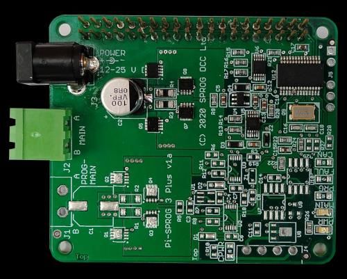
SPROG 3 Plus, Pi-SPROG 3 Plus, Pi-SPROG 3 v2 User Guide                                                                           2

Revision History ................................................................................................................ 5
   Acknowledgements ....................................................................................................... 5
Introduction ........................................................................................................................ 6
   Features.......................................................................................................................... 6
   Requirements................................................................................................................. 6
   Specification – Layout Power Districts........................................................................ 7
   Specification – Service Mode Programming ............................................................... 7
Hardware Details ................................................................................................................ 9
   SPROG 3 Plus ................................................................................................................ 9
      SPROG 3 Plus Front Panel ........................................................................................ 9
      SPROG 3 Plus Rear Panel .......................................................................................... 9
      USB Interface .............................................................................................................. 9
      Layout Interface .......................................................................................................... 9
      CBUS Interface............................................................................................................ 9
   Pi-SPROG 3 v2 ............................................................................................................. 10
   PI-SPROG 3 v2 Status LEDs ....................................................................................... 10
   Pi-SPROG 3 Plus ......................................................................................................... 11
   PI-SPROG 3 Plus Status LEDs ................................................................................... 11
      CBUS Interface.......................................................................................................... 11
Software Installation ........................................................................................................ 13
   Pi-SPROG 3 Plus and Pi-SPROG 3 v2 ........................................................................ 13
   SPROG 3 Plus .............................................................................................................. 13
      Install FTDI drivers (Windows/SPROG 3 Plus) ....................................................... 13
      Install DecoderPro .................................................................................................... 13
Hardware Setup ............................................................................................................... 14
   Connect the Power Supply ......................................................................................... 14
   Connect the Programming Track or Layout .............................................................. 14
   Connect the CBUS (Optional) – Plus Models Only ................................................... 14
Initial Setup Using Terminal Interface (Optional) .......................................................... 15
   The SPROG DCC Generation 5 Interface ................................................................... 15
   Checking the Firmware Version ................................................................................. 15
   Setting the CAN ID ....................................................................................................... 15
   Setting the Node Number............................................................................................ 16
   Changing Node Variables (NVs) ................................................................................. 16

 1.6.1 Sep 2021                                                                     © Copyright 2021 SPROG DCC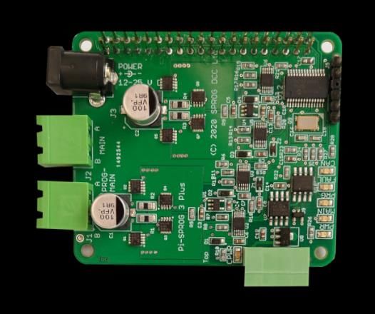
SPROG 3 Plus, Pi-SPROG 3 Plus, Pi-SPROG 3 v2 User Guide                                                                          3

   Reset SPROG 3 Plus to Factory Defaults .................................................................. 17
Getting Started with JMRI (DecoderPro and PanelPro) ................................................ 18
   Setting the JMRI Connection Preferences ................................................................ 18
SPROG DCC Generation 5 JMRI Tools .......................................................................... 20
   Pi-SPROG 3 v2 JMRI Tools ......................................................................................... 20
   Pi-SPROG 3 Plus and SPROG 3 Plus JMRI Tools ..................................................... 20
   Console ........................................................................................................................ 20
   CBUS Send Event Frame ............................................................................................ 21
   Node Manager .............................................................................................................. 21
   Command Station Monitor .......................................................................................... 23
   Mode Switching with SPROG 3 Plus and Pi-SPROG 3 Plus .................................... 24
      Programming Track Off When Not Programming .................................................. 24
      Programming Track Follows Main When Not Programming ................................ 24
      Programming Track is Auto-reverse District ......................................................... 25
   Mode Switching with Pi-SPROG 3 v2 ......................................................................... 25
      Programmer (Service mode programming) ............................................................ 25
      Command Station (Ops mode programming) ........................................................ 25
   Voltage/Current Meter ................................................................................................. 25
   The JMRI System console .......................................................................................... 26
   The JMRI Power Manager ........................................................................................... 27
A Brief Introduction to CBUS .......................................................................................... 28
Operation with JMRI and CBUS Cabs (Throttles) ......................................................... 30
   Release/Dispatch ......................................................................................................... 30
   Steal/Share ................................................................................................................... 30
CBUS Events and DCC Accessory Control ................................................................... 31
   Pi-SPROG 3 v2 ............................................................................................................. 31
   SPROG 3 Plus and Pi-SPROG 3 Plus ......................................................................... 31
      Short Events ............................................................................................................. 31
      Long Events .............................................................................................................. 31
   Mapping from CBUS Event Numbers to DCC Accessory Address ......................... 32
CBUS Node Variables ...................................................................................................... 33
   NV1 Command Station Number ................................................................................. 33
   NV2 User Flags ............................................................................................................ 33
   NV3 Operation Flags ................................................................................................... 34

 1.6.1 Sep 2021                                                                    © Copyright 2021 SPROG DCC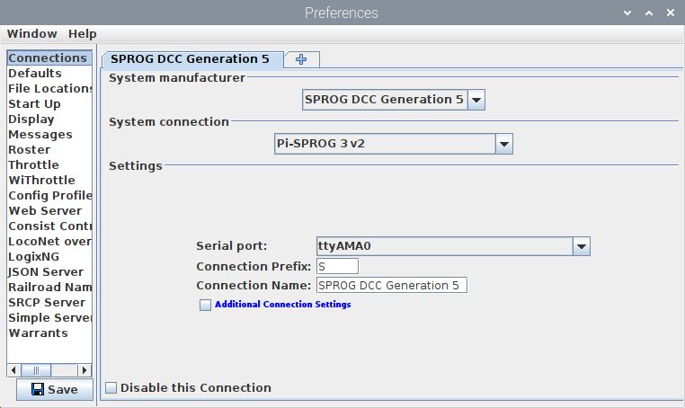
SPROG 3 Plus, Pi-SPROG 3 Plus, Pi-SPROG 3 v2 User Guide                                                                           4

   NV4 Debug Flags ......................................................................................................... 34
   NV5 Programming Track Power Mode ....................................................................... 34
      SPROG 3 Plus and Pi-SPROG 3 Plus ...................................................................... 34
      Pi-SPROG 3 v2 .......................................................................................................... 34
   NV6 Programming Track Current Limit, and ............................................................. 35
   NV13 Main Track Current Limit .................................................................................. 35
   NV7 Input Voltage ........................................................................................................ 35
   NV8 Main Track Current, and...................................................................................... 35
   NV14 Programming Track Current ............................................................................. 35
   NV9 DCC Accessory Packet Repeat Count ............................................................... 35
   NV10 Multimeter Mode ................................................................................................ 35
   NV11, NV12 Node Number to Map to DCC................................................................. 35
   NV15 Main Track Current High-Water Mark, and ...................................................... 35
   NV16 Programming Track Current High-Water Mark................................................ 35
   NV17 Setup Mode ........................................................................................................ 35
   NV18 CAN ID ................................................................................................................ 36
   NV19, NV20 Node Number .......................................................................................... 36
   NV21 DCC Preamble Bits ............................................................................................ 36
   NV22 CAN Disable ....................................................................................................... 36
CBUS Opcodes ................................................................................................................ 37
   OPCs Consumed ......................................................................................................... 37
   OPCs Output ................................................................................................................ 38
CBUS Events .................................................................................................................... 39
   Events Consumed ....................................................................................................... 39
   Events Produced ......................................................................................................... 39
Firmware Updates ............................................................................................................ 40
Differences to MERG CANCMD ...................................................................................... 42
Known Issues ................................................................................................................... 43
Glossary ........................................................................................................................... 44
Troubleshooting .............................................................................................................. 45
Useful Links ..................................................................................................................... 46

 1.6.1 Sep 2021                                                                     © Copyright 2021 SPROG DCC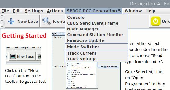
SPROG 3 Plus, Pi-SPROG 3 Plus, Pi-SPROG 3 v2 User Guide                                       5

Revision History
 Date     Version     Firmware   JMRI     Comment
 Jun-20   Draft 0.1   1.a.3      4.19.7   First version
 Dec-20   Draft 0.2   2.a.1      4.21.3   V2 SPROG 3 Plus, Pi-SPROG 3 Plus
 Feb-21   Draft 0.3   2.a.2      4.21.3   First draft release
 Mar-21   1.0         2.b.1      4.21.3   Support for SPROG 3 v2
 Apr-21   1.1         2.b.4      4.23.3   First Production release
 Apr-21   1.3         2.b.5      4.23.3   Pi-SPROG 3 v2 Photographs, update Known Issues
 May-21   1.4         2.b.6      4.23.4   Reformat. Throttle support. Differences to MERG CANCMD.
                                          Complete TODO items. Fix-typos
 Sep-21   1.5         2.c.1      4.24     See known issues list
 Sep-21   1.6         2.c.2      4.24     See known issues list
 Sep-21   1.6.1       2.c.3      4.24     See known issues list

Firmware and JMRI columns refer to the earliest versions to which a User Guide version
applies.

Acknowledgements
CBUS® is a registered trademark of Dr Michael Bolton.

1.6.1 Sep 2021                                              © Copyright 2021 SPROG DCC
SPROG 3 Plus, Pi-SPROG 3 Plus, Pi-SPROG 3 v2 User Guide                                  6

Introduction
The SPROG 3 Plus, PI-SPROG 3 v2 and Pi-SPROG 3 Plus are DCC decoder
programmers designed to support CBUS, a CAN based network developed by members of
MERG for model railway control.
The SPROG 3 Plus connects to the USB port of a personal computer or similar device.
The Pi-SPROG 3 v2 and Pi-SPROG 3 Plus attach directly to the GPIO connector of a
Raspberry-Pi computer. A Raspberry Pi 4 Model B is recommended for the best
performance.
All are supported by the free JMRI software (http://www.jmri.org/).
For the remainder of this document references to SPROG 3 Plus apply equally to the Pi-
SPROG 3 v2 and Pi-SPROG 3 Plus unless stated otherwise.
The SPROG 3 Plus and Pi-SPROG 3 Plus have two track outputs. With the supplied 5A
power supply each output can supply up to 2.5A to the layout
The Pi-SPROG 3 v2 is the replacement for the Pi-SPROG 3 which was, in turn, a
replacement (via firmware upgrade) for the Pi-SPROG One, and has a single track output
that can be used in programmer or command station modes supplying up to 2.5A to the
layout. It is not possible to upgrade from Pi-SPROG One or Pi-SPROG 3 to Pi-SPROG 3
v2, other than by purchasing the new hardware.

Features
   •   The SPROG 3 plus has an isolated USB interface to protect the host computer
   •   The Pi-SPROG 3 Plus has an isolated CBUS interface
   •   Flexible operating modes (Plus models only)
       •   One layout power district and one service mode programmer output
       •   Two layout power districts, one with auto switching to service mode
           programming track
       •   Two layout power districts, one with auto-reverse
   •   Flexible operating modes (v2)
       •   Programmer mode supporting service mode programming and test running of
           locos on a programming track
       •   Command station mode for full layout control
   •   Programs virtually all NMRA compliant DCC decoders
   •   No extra hardware required for programming sound decoders (e.g. programming
       booster) – but does not allow loading of sound projects.
   •   Easy to use graphical interface with DecoderPro

Requirements
   •   JMRI from http://www.jmri.org/

1.6.1 Sep 2021                                            © Copyright 2021 SPROG DCC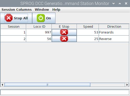
SPROG 3 Plus, Pi-SPROG 3 Plus, Pi-SPROG 3 v2 User Guide                                    7

  •   PI-SPROG 3 Plus and Pi-SPROG 3 v2 requirements:
      •    Raspberry-Pi (R-Pi 4 model B recommended)
      •    Raspbian OS image for the Pi-SPROG 3 Plus or v2
           •   See the image creation instructions on our website
           •   A suitable image may be purchased on micro SD card at the same time as
               the Pi-SPROG 3 Plus/v2 or downloaded from our website
           •   No drivers are required
  •   SPROG 3 Plus requirements:
      • FTDI VCP Windows USB drivers from https://ftdichip.com/drivers/vcp-drivers/ for
        the SPROG 3 Plus
      • No drivers are required for popular Linux distributions

Specification – Layout Power Districts
   Parameter                    Minimum       Nominal       Maximum        Units    Note
   DC Input supply voltage      12V                         25V            V        1
   Vin supply current – idle                  50                           mA
   Vin supply current –                                     5                       2
                                                                           A
   Operating Layout                                         2.5                     3
   Operating Temperature
                                              25                           °C
   Range
   Output Load – Operating
                                                            2.5            A        4
   Layout

                         Table 1 Specification/Operating Conditions
Notes:
    1.    The track voltage will be fractionally lower than the power supply input voltage.
    2.    Total for both outputs SPROG 3 Plus and Pi-SPROG 3 Plus
    3.    Pi-SPROG 3 v2
    4.    Per output. The combined output current limits must always be set lower than the
          power supply capability.

Specification – Service Mode Programming

   3                            Minimum       Nominal       Maximum        Units    Note
   Vin supply current –
                                              300                          mA       5
   programming
   Output Load - programming                                250            mA       5

                         Table 2 Specification/Operating Conditions

1.6.1 Sep 2021                                            © Copyright 2021 SPROG DCC
SPROG 3 Plus, Pi-SPROG 3 Plus, Pi-SPROG 3 v2 User Guide 8
Notes:
5. SPROG 3 Plus will remove track power if output current exceeds 250mA as
measured 100ms after applying power. Surge current during decoder power-up
may be considerably greater than this, but is allowed for.
1.6.1 Sep 2021 © Copyright 2021 SPROG DCCSPROG 3 Plus, Pi-SPROG 3 Plus, Pi-SPROG 3 v2 User Guide 9 Hardware Details SPROG 3 Plus SPROG 3 Plus Front Panel SPROG 3 Plus Rear Panel USB Interface USB reception (Rx) is indicated by a brief flash of the USB Rx LED. USB transmission (Tx) is indicated by a brief flash of the USB Tx LED Layout Interface Input power is indicated by the red PWR LED. The track activity is indicated by the MAIN and PROG red LEDs, which will illuminate steadily when their respective outputs are powered up. When the PROG output is being used for a programming track, the PROG LED will flash slowly when power is applied during a programming operation. A fast flash on the MAIN or PROG LEDs indicates an overload condition. CBUS Interface The CBUS interface status is indicated with three red LEDs. The CBUS RX LED flashes when a CBUS frame is received. The CBUS TX LED flashes when a CBUS frame is transmitted. The CBUS CFLT LED indicates a fault on the CBUS interface. 1.6.1 Sep 2021 © Copyright 2021 SPROG DCC
SPROG 3 Plus, Pi-SPROG 3 Plus, Pi-SPROG 3 v2 User Guide                                    10

All three LEDs are illuminated when the module starts up. The CBUS RX and TX LEDS
remain illuminated until data is received or transmitted on CBUS.
The CFLT LED will extinguish on the first CBUS frame and then illuminate if there is a fault
on the CBUS interface.
When the module starts up (e.g., after applying power) the PROG, MAIN and CFLT LEDs
will illuminate and then extinguish at 0.5 second intervals. CFLT will remain in the case of
a fault on the CBUS interface (e.g., not connected).
The PWR LED will remain illuminated whilst power is applied.

Pi-SPROG 3 v2

      PWR

               A
      MAIN
               B

                                                                             MAIN

                                                                             PWR

PI-SPROG 3 v2 Status LEDs
Input power is indicated by the red PWR LED (See known Issues in this document).
The track activity is indicated by the MAIN LED, which will illuminate steadily when the
output is powered up.
The MAIN LED will flash slowly when power is applied during a service mode
(programming track) programming operation.
A fast flash on the MAIN LED indicates an overload condition.
The MAIN LED will flash if Power is not connected.

1.6.1 Sep 2021                                            © Copyright 2021 SPROG DCC
SPROG 3 Plus, Pi-SPROG 3 Plus, Pi-SPROG 3 v2 User Guide 11
Pi-SPROG 3 Plus
PWR
A ACT
MAIN
B
FAULT
A
PROG PROG
B
MAIN
PWR
CPWR CBUS
PROG output, CBUS interface, and associated components are not present on Pi-SPROG
3 v2.
PI-SPROG 3 Plus Status LEDs
Input power is indicated by the red PWR LED.
The track activity is indicated by the MAIN and PROG red LEDs, which will illuminate
steadily when their respective outputs are powered up.
When the PROG output is being used for a programming track, the PROG LED will flash
slowly when power is applied during a programming operation.
A fast flash on the MAIN or PROG LEDs indicates an overload condition on the respective
output.
The MAIN and PROG/MAIN LEDs will flash together and the if power is not connected.
CBUS Interface
The CBUS interface status is indicated with three red LEDs.
The CBUS activity, ACT, LED flashes on CBUS frame transmission and reception.
The CBUS FAULT LED indicates a fault on the CBUS interface.
Both ACT and FAULT LEDs are illuminated when the module starts up.
The ACT LED will extinguish on the first CBUS frame and then flash for each subsequent
CBUS frame.
The FAULT LED will extinguish on the first CBUS frame and then illuminate if there is a
1.6.1 Sep 2021 © Copyright 2021 SPROG DCCSPROG 3 Plus, Pi-SPROG 3 Plus, Pi-SPROG 3 v2 User Guide 12 fault on the CBUS interface. The CBUS power, CPWR, LED indicates the presence of power on the CBUS connection. When the module starts up (e.g., after applying power) the PROG, MAIN and CFLT LEDs will illuminate and then extinguish 0.5 second intervals. CFLT will remain in the case of a fault on the CBUS interface (e.g., not connected). The PWR LED will remain illuminated whilst power is applied. 1.6.1 Sep 2021 © Copyright 2021 SPROG DCC
SPROG 3 Plus, Pi-SPROG 3 Plus, Pi-SPROG 3 v2 User Guide                                13

Software Installation

Pi-SPROG 3 Plus and Pi-SPROG 3 v2
The Pi-SPROG family require an SD card to be created with a suitable operating system
(OS) and software image. Three possible routes to obtain the SD card image are:
   •   Purchase a ready built SD card from us
   •   Download the image from our website https://www.sprog-dcc.co.uk/download-page
   •   Create your own image following the instructions on our website https://www.sprog-
       dcc.co.uk/download-page

SPROG 3 Plus
The following steps are required to install the SPROG 3 Plus on your computer before you
can use it for the first time:
   •   Install FTDI drivers (Windows only)
   •   Install DecoderPro 4.23.4 or later

Install FTDI drivers (Windows/SPROG 3 Plus)
Install the drivers from the optional USB stick (if purchased with the SPROG 3 Plus) or
download from https://ftdichip.com/drivers/vcp-drivers/ for the SPROG 3 Plus on Windows.

Install DecoderPro
DecoderPro should be installed from the optional USB stick (if purchased with the SPROG
3 Plus) or a downloaded copy.
A newer version of DecoderPro than that supplied on the USB stick may be available from
the JMRI download page http://www.jmri.org/download
This user guide assumes you are using version 4.23.4, or later.
To install from the USB key, browse to the directory specific to your operating system to
find the JMRI installer. For example, if your USB key drive is D: on Windows, double click
on the file D:\Windows\JMRI.4.23.4.exe.

1.6.1 Sep 2021                                           © Copyright 2021 SPROG DCC
SPROG 3 Plus, Pi-SPROG 3 Plus, Pi-SPROG 3 v2 User Guide 14
Hardware Setup
Connect the Power Supply
The supplied power supply has a standard 2.1mm DC barrel connector (centre positive),
that plugs directly in to the SPROG 3 Plus
Connect the Programming Track or Layout
Layout power districts may be connected to both MAIN and PROG track outputs. PROG
is, optionally, the auto-reverse power district.
If using a service mode programming track with SPROG 3 Plus or Pi-SPROG 3 Plus, this
must be connected to the PROG output.
! Care should be taken when using the service mode programmer that the
programming track is isolated from the layout.
The MAIN output of the Pi-SPROG 3 v2 can function as either a service mode
programming track output or main layout track output.
! Care should be taken when using the Pi-SPROG 3 v2 as a service mode
programmer that the programming track is isolated, or all locos are removed from
the layout, apart from the one to be programmed.
For all but the smallest layouts you should use a substantial power bus around the layout
with short, thinner “droppers” to individual track segments. Avoid relying on rail joiners for
conducting power around the layout.
Connect the CBUS (Optional) – Plus Models Only
CBUS requires at least a 3-way connection for proper operation. CAN HI, CAN LO and 0V.
Many modules will also require an external 12V DC power supply that may be connected
via the CBUS connector, or by alternate means.
The SPROG 3 Plus CBUS interface is internally powered and no 12V connection is
required. The 4th pole of the CBUS connector may be safely connected to 12V (e.g., to
standardize connector wiring) but is not connected internally, and will not draw any current.
The Pi-SPROG 3 plus CBUS interface is galvanically isolated and 12V power must be
applied to the CBUS connector.
The CBUS must be correctly terminated for proper operation. For very small installations a
single 60 ohm resistor is often sufficient. For larger installations a 120 ohm resistor should
be connected across CAN HI and LO at each end of the bus.
1.6.1 Sep 2021 © Copyright 2021 SPROG DCCSPROG 3 Plus, Pi-SPROG 3 Plus, Pi-SPROG 3 v2 User Guide 15 Initial Setup Using Terminal Interface (Optional) The SPROG DCC Generation 5 Interface The SPROG 3 Plus is a SPROG Generation 5 products. The interface between the host and the SPROG 3 Plus is CBUS, using the GridConnect protocol The Plus models may also be connected to a CBUS network but this is not required to operate run trains and operate DCC accessories on a layout. The SPROG 3 Plus also supports an additional command set that may be access through a terminal emulator program such as PuTTY https://www.chiark.greenend.org.uk/~sgtatham/putty/ This can be used for module setup and CBUS testing. The SPROG 3 Plus includes a bootloader that allows firmware updates to be installed by the user. JMRI must not be connected to the SPROG 3 Plus when using the terminal interface. Use a terminal emulator program set to 460800 baud, 8 bits, no parity, 1 stop bit to connect to the SPROG. Commands may be typed in upper or lower case. All numeric entry is assumed to be decimal. All commands should be followed by a carriage return. The SPROG 3 Plus does not echo characters back to the terminal. Local echo can be enabled in the PuTTY Terminal options to show what you have typed. The SPROG 3 Plus does not allow backspace to be used. Checking the Firmware Version Use the ? command to check the firmware version. This will also display the current CAN ID and CBUS Node Number Setting the CAN ID The I command will show the current CAN ID. 1.6.1 Sep 2021 © Copyright 2021 SPROG DCC
SPROG 3 Plus, Pi-SPROG 3 Plus, Pi-SPROG 3 v2 User Guide                                  16

A new ID may be set by following the I command with a number in the range 1 – 127. The
new ID will be displayed. The old ID will be displayed if the new value is invalid.

It is recommended that modules such as the SPROG 3 Plus, with a fixed CAN ID, have a
CAN ID in the range 100 – 127.
Any CBUS traffic from JMRI will use the CAN ID assigned in the JMRI connection
preferences.
CBUS traffic generated from the SPROG 3 Plus itself will use the SPROG 3’s own CAN ID
which is 114 in a new module.
All modules must have a unique CAN ID.

Setting the Node Number
The N command will show the current Node Number.
A new NN may be set by following the I command with a number in the range 1 – 65535.
The new NN will be displayed. The old NN will be displayed if the new value is invalid.

The SPROG 3 Plus Node number is 65534 in a new module.
It is recommended, but not required for more advanced users, that all modules have a
unique Node Number when using CBUS.
It is recommended that modules such as the SPROG 3 Plus, with a fixed NN, have an NN
in the range 65520 - 65535.

Changing Node Variables (NVs)
The V command will show the current value of an NV.
A new value may be written to an NV by giving the value in the range 1 – 255. The new
NV value will be displayed. The old NV value will be displayed if the new value is invalid.
The example shows setting the CAN ID through NV18.

1.6.1 Sep 2021                                            © Copyright 2021 SPROG DCC
SPROG 3 Plus, Pi-SPROG 3 Plus, Pi-SPROG 3 v2 User Guide                              17

Take care to understand what you are doing when changing NVs.
See CBUS Node Variables for the NVs supported by the Pi-SPROG 3 Plus

Reset SPROG 3 Plus to Factory Defaults
The R command will reset the SPROG 3 Plus to the factory default, notably the CAN ID
and Node Number. The output is similar to the ? command, showing the firmware version,
ID and NN.
To prevent inadvertent resets, the R command must be followed by 3 parameters of any
value between 0 and 65535. In the following example, R with no parameters has no effect.

The R command DOES NOT revert to the original firmware version, if updates have been
applied.

1.6.1 Sep 2021                                         © Copyright 2021 SPROG DCC
SPROG 3 Plus, Pi-SPROG 3 Plus, Pi-SPROG 3 v2 User Guide                                   18

Getting Started with JMRI (DecoderPro and PanelPro)
DecoderPro and PanelPro are different interfaces to the same underlying JMRI software.
The split exists for historical reasons only. There are some differences in the functions that
are available from the menus but a lot of features are available through both interfaces.
It has become customary to think of DecoderPro as the tool for programming decoders
and PanelPro for controlling a layout.
DecoderPro will often be used with a dedicated programming track for ‘service mode’
programming. This allows full read and write access to all Configuration Variables (CVs) in
a single decoder.
PanelPro will often be used with ‘on the main’ or ‘ops mode’ programming in conjunction
with layout control. In this mode CVs may be written, but (without special hardware such
as Railcom) values cannot be read back. The SPROG 3 Plus does not support reading
from decoder in ops mode. The advantage of ops mode programming is that any loco, out
of all the locos on a layout, may be programmed. Unlike service mode there is no single
loco limit.
It is possible to access all the features of JMRI (Roster, Panels, Tables, Programmer, etc,
…) through either interface, but the menu structure is different.
With the SPROG 3 Plus and the Pi-SPROG 3 Plus, use the Mode Switch tool to select
either ‘Programming track off when not programming’ (recommended for new users) or
‘Programming track follows main when not programming’ to use a service mode
programming track.

!   Care should be taken when using the service mode programmer that the
    programming track is isolated from the layout.
With the Pi-SPROG 3 v2, use the Mode Switch tool to select either ‘Programming
(Service Mode Programming)’ or ‘Command Station (Ops mode programming)’ to use a
service mode programming track.

!   Care should be taken when using the Pi-SPROG 3 v2 as a service mode
    programmer that the programming track is isolated, or all locos are removed from
    the layout, apart from the one to be programmed.

Setting the JMRI Connection Preferences
For the Pi-SPROG 3 Plus and Pi-SPROG 3 v2, if you downloaded or purchased an SD
card image then this step can be skipped.
If setting up your own system then please be sure to select SPROG DCC Generation 5
(NOT simply SPROG DCC) as the System Manufacturer and the appropriate System
Connection in the connection preferences for DecoderPro or PanelPro.
On Windows systems, the COM port required for the Serial port entry may be determined
by looking for the SPROG 3 Plus in the Windows Device Manager under “Ports COM &
LPT”. The SPROG 3 Plus will appear as a USB Serial port.
On Linux the SPROG 3 Plus USB interface should be created as ttyUSBx when x will
depend on what other hardware is connected to the system.

1.6.1 Sep 2021                                             © Copyright 2021 SPROG DCC
SPROG 3 Plus, Pi-SPROG 3 Plus, Pi-SPROG 3 v2 User Guide 19 For the Pi-SPROG 3 Plus, Pi-SPROG 3 v2, if you have followed our recommended image creation, select the ttyAMA0 serial port. Save the new settings and restart JMRI or PanelPro. Further details of the general features of JMRI are beyond the scope of this document. Please consult the on-line help in the software or on the JMRI help webpages. SPROG specific features are described next. 1.6.1 Sep 2021 © Copyright 2021 SPROG DCC
SPROG 3 Plus, Pi-SPROG 3 Plus, Pi-SPROG 3 v2 User Guide                                20

SPROG DCC Generation 5 JMRI Tools
A number of tools are available on the SPROG DCC Generation 5 menu.

Pi-SPROG 3 v2 JMRI Tools

Pi-SPROG 3 Plus and SPROG 3 Plus JMRI Tools

A selection of these are descibed in more detail below. The Firmwware Update Tool is
described in a later section.

Console
The console shows the CBUS frames sent to/from SPROG 3 Plus and the host. It is useful
for capturing diagnostic information if a problem occurs that is repeatable.
Various display options re selectable and the output may be logged to a file.

1.6.1 Sep 2021                                           © Copyright 2021 SPROG DCC
SPROG 3 Plus, Pi-SPROG 3 Plus, Pi-SPROG 3 v2 User Guide                                  21

CBUS Send Event Frame
The send event frame tool allows CBUS events to be sent manually, e.g., for testing or
setting up.
On the Pi-SPROG 3 v2 (that has no CBUS interface) events will always be translated into
DCC accessory commands using the Event Number as the DCC accessory address.

Node Manager
The node Manager allows access to internal settings in the SPROG 3 Plus. It is not
required for normal, everyday, operation, unless you need to change some aspect of the
SPROG 3 Plus operation (Older SPROG users may think of this as being similar to setting
the SPROG mode word).
The node manager is started from the SPROG DCC Generation 5 > Node Manager menu
item.
Select the option ‘Add Command Stations when found’ and ‘Add Nodes when found’ in the
Options menu.

1.6.1 Sep 2021                                          © Copyright 2021 SPROG DCC
SPROG 3 Plus, Pi-SPROG 3 Plus, Pi-SPROG 3 v2 User Guide                                22

Click ‘Search for Nodes and Command Stations’ in the Options menu

The SPROG 3 Plus should respond as a Command Station

Click OK.

In the Node Info tab you can see details such as the firmware version of the SPROG 3
Plus

The Node Variables (NVs) control the operation and show the internal status of the
SPROG 3 Plus, much like the CVs in a DCC decoder.

1.6.1 Sep 2021                                          © Copyright 2021 SPROG DCC
SPROG 3 Plus, Pi-SPROG 3 Plus, Pi-SPROG 3 v2 User Guide                               23

To change an NV use the spinner to select the new value, or type the new value directly,
click the save button and then confirm the operation in the pop up dialog.
Take care to understand what you are doing when changing NVs.
Not all NVs are supported on all hardware variants. See CBUS Node Variables

Command Station Monitor
When using the SPROG 3 Plus as a command station controlling multiple locos, you can
see the status of all locos in the command station monitor.
Emergency stop and power control buttons are also provided in the command station
monitor window.

1.6.1 Sep 2021                                          © Copyright 2021 SPROG DCC
SPROG 3 Plus, Pi-SPROG 3 Plus, Pi-SPROG 3 v2 User Guide                                24

Mode Switching with SPROG 3 Plus and Pi-SPROG 3 Plus
The mode switcher controls the operating mode of the programming track output.
With the SPROG 3 Plus and Pi-SPROG 3 Plus, three operating modes are available.

Programming Track Off When Not Programming
In this mode the programming track output supports service mode programming and is
turned off when not programming. This mode would typically be used where the
programming track is close to, but not connected to, the main layout. Locos to be
programmed would be lifted from the layout and placed on the programming track.
Layout operation may continue whilst programming.

Programming Track Follows Main When Not Programming
In this mode the programming track output supports service mode programming and is
linked internally to the main track output. When not programming, the programming track
output will follow the main track output, e.g., to allow locos to be driven from the main
layout to a spur or siding being used as a programming track.

1.6.1 Sep 2021                                           © Copyright 2021 SPROG DCC
SPROG 3 Plus, Pi-SPROG 3 Plus, Pi-SPROG 3 v2 User Guide                                  25

Care must be taken that nothing bridges between the programming track and the main
layout when programming starts.
Layout operation may continue whilst programming.

Programming Track is Auto-reverse District
In this mode the programming track output does not support service mode programming.
Instead, it can be used as a second layout power district with auto-reverse.

Mode Switching with Pi-SPROG 3 v2
With the Pi-SPROG 3 v2, only two operating modes are available.

!   Always close and reopen any programmer windows when switching modes to
    ensure they reflect the programming modes.

Programmer (Service mode programming)
In this mode the track output support service mode programming on a programming track
with full read and write access to CVs. A single throttle can be used for test running. Care
must be taken not to use this mode when connected to a layout as all locos on the layout
will be reprogrammed.

Command Station (Ops mode programming)
In this mode the programming track support Operations mode or on the main programming
and multiple throttles for layout control.

Voltage/Current Meter
If Node Variable 10, Multimeter Mode, is set to 1 then the SPROG 3 Plus will send regular
voltage and current measurements (approx. every 2s) to the host and to CBUS. These
may be displayed with JMRI Voltage/Current meters.
Open a meter from the SPROG DCC Generation 5 menu

1.6.1 Sep 2021                                            © Copyright 2021 SPROG DCC
SPROG 3 Plus, Pi-SPROG 3 Plus, Pi-SPROG 3 v2 User Guide 26 Set the meter to be a voltage or current meter The voltage meter monitors the input supply voltage. The DCC track voltage will be slight less than this. The SVCBUSCurrentMeter displays the main track current. The SV2CBUSCurrentMeter displays the programming track current. The voltage and current measurements are for information only and accurate to +/-5%. The current readings, especially, may fluctuate to a marked extent. The JMRI System console The JMRI system console can be opened from the Help > System console menu item. 1.6.1 Sep 2021 © Copyright 2021 SPROG DCC
SPROG 3 Plus, Pi-SPROG 3 Plus, Pi-SPROG 3 v2 User Guide                               27

The system console contents may be useful when something goes wrong. Look for
ERROR or WARNING messages.

The JMRI Power Manager

The state of the track power can be controlled through the Power Control.

Or by clicking the icon that appears in various windows, e.g., throttles

!   During programming the prog track power will be controlled automatically but will
    not be reflected in the power manager.
By default, the power is always off at startup. This behaviour can be changed by setting
the User Flags Auto power bit. The hardware will broadcast the power state during startup.
For all Pi-SPROGs, the initial power state will show as Unknown in JMRI as the hardware
starts up before the software and the broadcast message is not seen.
For the SPROG 3 Plus the initial power state displayed by JMRI will depend whether the
hardware or software starts up first. If JMRI is started before power is connected to the
SPROG 3 Plus then the power state will reflect the Auto Power setting, once the hardware
startup is complete.

1.6.1 Sep 2021                                          © Copyright 2021 SPROG DCC
SPROG 3 Plus, Pi-SPROG 3 Plus, Pi-SPROG 3 v2 User Guide 28 A Brief Introduction to CBUS The Pi-SPROG 3 v2 uses the CBUS protocol for communicating with the host only. It does not have an external CBUS interface. Only a brief description of CBUS can be given here. CBUS was developed by members of the Model Electronics Railway Group (MERG) and the protocol and other documents were hosted on the MERG website. ‘Ownership’ oe ‘control’ of CBUS vests in those individual, not in MERG. Please refer to documentation on the MERG website for more in-depth information on CBUS. CBUS is a Layout Control Bus (LCB), much like, e.g., Loconet® (trademark of Digitrax Inc.) or XpessNet, a communications network that allows electronic modules on a model railway to be connected, often to some form of personal computer (but not required). The modules that can be connected to CBUS include, but are not limited to, command stations (such as the SPROG 3 plus family), throttles, control panels, turnout and signal control, block detectors. Using an LCB such as CBUS can save a lot of wiring on the layout by using just a few wires to connect all of the various elements together. For example, many switches on a control panel can control turnouts and signals in diverse locations on the layout with just a few wires. CBUS, as used in the SPROG 3 plus family, is based on the Controller Area Network (CAN) bus, widely used, for many years, in the automotive and transport industries. Using CAN allows the choice of a wide range of well understood and cost-effective components to implement the interface to the connected modules. As well as layout control messages, CBUS allows modules to be configured, e.g., to control how outputs are driven or how inputs are sensed. Each module is built with stored parameters that can be interrogated to determine its functionality. Operation is controlled by writing to Node Variables (NVs). This is comparable to reading and writing CVs in a DCC decoder, but uses a different process. Whilst CBUS can be, and often is, used with a personal computer, it does not require a single “master” module. All modules co-exist on the network and can talk to each other at any time. Compare this to some other LCBs where each module may only send data when it is “polled” or asked for it. All SPROG 3 Plus family modules include a host interface and do not require a separate interface module. A CBUS module typically forms a CBUS Node but it is possible that a single module could implement multiple CBUS nodes with similar or differing functions. All CBUS messages (or events) include an Op-Code (OPC) which determines the nature of the message. For some OPCs, the sender will include its own Node Number (NN) in the message. Events will include an Event Number (EN). Layout control can thus be based on what is to happen (OPC) who sent the message (NN) and where it must happen (EV). CBUS modules are ‘taught’ to send certain events to CBUS or recognize and respond to certain EVs from certain NNs from CBUS. How the module generates the event or what it does with a received event is very much module dependent. A simple example would be a control panel switch connected to a module that sends event X when the switch is closed. 1.6.1 Sep 2021 © Copyright 2021 SPROG DCC
SPROG 3 Plus, Pi-SPROG 3 Plus, Pi-SPROG 3 v2 User Guide                                  29

Another module is taught to do something (e.g., change the direction of a cross-over)
when it sees that event.
CBUS can be used, indeed was originally intended to be used, in a strict ‘producer-
consumer’ mode in which each event has a single producer that sends, or produces, an
event and one or many consumers that listen for, or consume, that event. In this case the
NN is an integral part of the event and consumers will also be taught the NN to be
recognized when consuming an event. These events, including the NN and EN are known
as ‘long events’.
To add flexibility CBUS can also operate in a ‘many-to-many’ mode in which multiple
producers can produce the same event. These are known as ‘short events’. The NN is still
included in the message (for diagnostic purposes) but is ignored by the consumer.
CBUS consumer modules may have Event Variables (EVs) associated with each event
that they are taught. The meaning of any EV is module dependent and beyond the scope
of this document. Typical useof an EV would be to modify the result of an event by, e.g.,
inverting the polarity of an output or setting a time for an output to be turned on or off.
CBUS modules may have Node Variables (NVs) that control the operation of the module
as a whole, such as controlling initial behaviour at startup.

1.6.1 Sep 2021                                            © Copyright 2021 SPROG DCC
SPROG 3 Plus, Pi-SPROG 3 Plus, Pi-SPROG 3 v2 User Guide                                         30

Operation with JMRI and CBUS Cabs (Throttles)
The Pi-SPROG 3 v2 support running trains with JMRI throttles, including WiThrottle
connected devices. It does not directly support physical cabs as it has no CBUS interface.
The Pi-SPROG 3 Plus and SPROG 3 plus support running trains with JMRI throttles,
including WiThrottle connected devices and physical throttles connected to CBUS.
At the time of writing, the only physical throttle that has been tested is the MERG
CANCAB. This is available as a kit to MERG members. See MERG documentation for full
details of how to use the CANCAB.

Release/Dispatch
When you release a loco whilst it is moving, it is considered to be “dispatched”, but the
loco is not forgotten. The loco is driven at the current speed until it is reselected, by the
same, or another, cab.

Steal/Share
It is possible for one cab to steal a loco from another cab, e.g., when handing a train over
to another operator. Users will be notified by messages on the cab screen or computer
sreen if using a JMRI throttle.
Similarly, two or more (up to 3) cabs may share a loco.

1.6.1 Sep 2021                                               © Copyright 2021 SPROG DCC
SPROG 3 Plus, Pi-SPROG 3 Plus, Pi-SPROG 3 v2 User Guide                                   31

CBUS Events and DCC Accessory Control
If a layout is already equipped with DCC accessory decoders then there is no need to
replace these with CBUS modules to control points, signals, etc.
CBUS events may be used to generate DCC accessory commands that will be sent on the
track output(s).
The CBUS events should, if possible, be chosen to map the the existing DCC accessory
addresses.

! Note that accessory control from a CANCAB uses short events.
Pi-SPROG 3 v2
The CBUS Node Number will be ignored and a short or long event will be mapped from
the Event Number to a DCC accessory address as described below. CBUS on events
(ACON, ASON) will turn the DCC accessory on. CBUS off events (ACOF, ASOF) will turn
the DCC accessory off.

SPROG 3 Plus and Pi-SPROG 3 Plus
At the time of writing, a very simple scheme exists to map CBUS events to DCC accessory
commands.
It is intended that a more sophisticated method will be implemented in a future firmware
release.
User flags bit 1 must be set to map CBUS events to DCC accessory commands, otherwise
CBUS control of DCC accessories is outside the scope of the SPROG 3 Plus.

Short Events
The CBUS Node Number will be ignored and a short or long event will be mapped from
the Event Number to a DCC accessory address as described below. CBUS on events
(ASON) will turn the DCC accessory on. CBUS off events (ASOF) will turn the DCC
accessory off. This is similar to the behaviour of the Pi-SPROG 3 v2.

Long Events
Mapping between CBUS events and DCC accessory addresses is controlled by Node
Variables. See NV11, NV12 Node Number to Map to DCC
When NV11 and NV12 are both zero, the CBUS Node Number will be ignored and a long
event will be mapped from the Event Number to a DCC accessory address as described
below. CBUS on events (ACON) will turn the DCC accessory on. CBUS off events (ACOF)
will turn the DCC accessory off. This is similar to the behaviour for short events and the Pi-
SPROG 3 v2.
If the NV11, NV12 pairing is non-zero then the value formed with NV11 being the high byte
and NV12 the low byte is used as a Node Number to match against the Node Number of a
CBUS long event. If the Node Number in the event matches the Node Number in NV11/12

1.6.1 Sep 2021                                             © Copyright 2021 SPROG DCC
SPROG 3 Plus, Pi-SPROG 3 Plus, Pi-SPROG 3 v2 User Guide                             32

then the long event will be mapped from the Event Number to a DCC accessory address
as described below. CBUS on events (ACON) will turn the DCC accessory on. CBUS off
events (ACOF) will turn the DCC accessory off.

Mapping from CBUS Event Numbers to DCC Accessory Address
JMRI turnout numbers for CBUS, and hence the associated CBUS events, start from 1
whereas DCC accessory addresses start from 0.
CBUS events are mapped to DCC accessory addresses by subtracting one from the Event
Number.
E.g., ACON event with EN=1234 will send DCC on command to accessory address 1233.
Consideration must also be given to the way in which various manufacturers have chosen
to interpret DCC accessory addresses. The mapped CBUS event may not correspond
directly to a DCC accessory address recognised by a DCC accessory decoder that has
been programmed on a different DCC system.

1.6.1 Sep 2021                                        © Copyright 2021 SPROG DCC
SPROG 3 Plus, Pi-SPROG 3 Plus, Pi-SPROG 3 v2 User Guide                                              33

CBUS Node Variables
NVs control the operation and show the internal status of the SPROG 3 Plus, much like
the CVs in a DCC decoder.
NVs may be changed through the terminal interface or through the JMRI node manager.
At the time of writing, the SPROG 3 Plus is not supported by the FCU (a configuration tool
written and supported by MERG members).
A sub-set of the NVs are available on the Pi-SPROG 3 v2. These are indicated by an X in
the v2? column in the following table.

 Node       Values     Default     v2?   Function
 Variable
 1          0          0           X     Command station number
 2          0 – 255    118         X     User flags
 3          0 – 255    0           X     Operation flags
 4          0          0           X     Debug flags – not currently used
 5          0,1,2      0           X     Programming track power mode
 6          0 – 255    25          X     Programming track current limit, Amps x 10
 7          0 – 255    -                 Read only input voltage, Volts x 10, e.g. 118 represents 11.8 V
 8          0 - 255    -                 Read only main track current, Amps x 10
 9          1–7        1                 Accessory packet repeat count.
 10         0,1        0                 Multimeter mode. Set to 1 to enable voltage and current events.
 11         0 – 255    0                 NN to map to DCC hi byte
 12         0 – 255    0                 NN to map to DCC lo byte
 13         0 – 255    25                Main track current limit, Amps x 10
 14         0 – 255    -           X     Read only programming track current, Amps x 10
 15         0 – 255    -                 Read only main track current high-water mark, in Amps x 10
 16         0 – 255    -           X     Read only programming track current high-water mark, Amps x
                                         10
 17         0,1        0                 Setup mode – do not use
 18         1 – 127    114               CAN ID
 19         0 – 255    255         X     Node Number high byte
 20         0 – 255    254         X     Node Number low byte
 21         16 - 255   16          X     Number of DCC preamble bits transmitted
 22         0, 1       0                 CAN disable

NV1 Command Station Number
Only command station 0 is currently supported. Any other values will be ignored.

NV2 User Flags
The user flags NV contains 8 bits.
The default value is 01110110 or hex 76 or decimal 118.
Reserved bits should always be set to 0 and will read as zero.
 Bit   Default   Function
 0     0         Reserved
 1     1         Permit Steal: Set to enable throttle steal option
 2     1         Permit Share: Set to permit throttle share option
 3     0         Reserved

1.6.1 Sep 2021                                                       © Copyright 2021 SPROG DCC
SPROG 3 Plus, Pi-SPROG 3 Plus, Pi-SPROG 3 v2 User Guide 34
Bit Default Function
4 1 Map Events: Set to map CBUS events to DCC accessory packets
5 1 Stop on Timeout: If set and a loco session times out, the train is brought to a stop. If
clear the train is dispatched whilst moving
6 1 Start of Day: Set to send CBUS even 0 on startup which may be used as a start of
day event
7 0 Auto Power: Set to turn track power on at startup
NV3 Operation Flags
The operation flags NV contains 8 bits.
The default value is 0.
Reserved bits should always be set to 0 and will read as zero.
Bit Default Function
0 0 Reserved
1 0 Reserved
2 0 Reserved
3 0 ZTC Mode: Set to modify bit timing when programming for ZTC decoders
4 0 All stop track off: Set to turn track power off if an all stop command is issued
5 0 Blueline Mode: Modify programming operation to suit blueline decoders
6 0 ACK sensitivity: Set to modify programming ACK pulse detection for certain large
scale Zimo decoders
7 0 Reserved
NV4 Debug Flags
Debug flags NV is currently reserved. All bits will read as zero.
NV5 Programming Track Power Mode
The way the programming track works is controlled by Node Variable 5 and can have one
of three values
SPROG 3 Plus and Pi-SPROG 3 Plus
NV5 Mode
0 Programming Track Off When Not Programming
Programming track is independent of main track and is off when not programming
1 Programming Track Follows Main When Not Programming
Programming track follows main track when not programming
2 Programming Track is Auto-reverse District
Programming track follows main track
Auto reverse on overload
Pi-SPROG 3 v2
NV5 Mode
0 Programmer Mode
Service mode programming packets will be generated for use with a programming track
1 Command Station Mode
Operations mode programming packets will be generated for “ops-mode” or “on the main”
programming
1.6.1 Sep 2021 © Copyright 2021 SPROG DCCSPROG 3 Plus, Pi-SPROG 3 Plus, Pi-SPROG 3 v2 User Guide 35 NV6 Programming Track Current Limit, and NV13 Main Track Current Limit Current trip limits to be applied to the two track outputs in Amps x 100, e.g., a value of 200 will apply a current limit of 2.0A. NV7 Input Voltage Measured input supply voltage in Volts x 10, e.g., 125 represents 12.5V. NV8 Main Track Current, and NV14 Programming Track Current Current measurement in Amps x 100, e.g., 70 represents 0.7A or 700mA. NV9 DCC Accessory Packet Repeat Count Range 1 – 7. The number of times a DCC accessory packet is repeated. If DCC accessories do not operate reliably, try increasing the repeat count by 1. NV10 Multimeter Mode 0 – Multimeter events disabled 1 – Multimeter current/voltage measurement events enabled NV11, NV12 Node Number to Map to DCC Set to zero to map all short events directly to DCC accessory commands where the event number becomes the DCC accessory number. Set a non-zero value to match a specific node number and map all long events from that node to DCC accessory commands. NV11 is the high byte of the Node Number. NV15 Main Track Current High-Water Mark, and NV16 Programming Track Current High-Water Mark The current high-water marks store the highest measured current as Amps x 100 (e.g., a value of 130 represents 1.3 Amps). The high-water marks can be reset by writing 0 to the appropriate NV. NV17 Setup Mode Use with caution. Set bit 1 of NV17 to put the SPROG 3 Plus in setup mode. 1.6.1 Sep 2021 © Copyright 2021 SPROG DCC
SPROG 3 Plus, Pi-SPROG 3 Plus, Pi-SPROG 3 v2 User Guide                                36

NV18 CAN ID
It is recommended that modules such as the SPROG 3 Plus, with a fixed CAN ID, have a
CAN ID in the range 100 – 127.

NV19, NV20 Node Number
Range: 0 – 255.
High and low byte, respectively of the CBUS node number. Overall range is 0 – 65535.

NV21 DCC Preamble Bits
The number of preamble bits sent before each DCC packet.

NV22 CAN Disable
0 – CAN bus is enabled (normal operation).
1 – CAN bus is disabled (for test purposes).

Voltage and current measurements are for information only and accurate to +/-5%.

1.6.1 Sep 2021                                         © Copyright 2021 SPROG DCC
SPROG 3 Plus, Pi-SPROG 3 Plus, Pi-SPROG 3 v2 User Guide                              37

CBUS Opcodes

OPCs Consumed
CBUS Opcode      Action                      Comment
(OPC)
ACOF             Send DCC accessory packet
ACON             Send DCC accessory packet
ARST             System reset                Software reset – not on Pi-SPROG 3 v2
ASOF             Send DCC accessory packet
ASON             Send DCC accessory packet
BOOT             Enter boot mode
CANID            Set CAN ID                  Not on Pi-SPROG 3 v2
DFNOF            Function update             By function
DFNON            Function update             By function
DFUN             Function update             By function group
DKEEP            Keep alive
DSPD             Speed update
GLOC             Request session
KLOC             Release loco
NNRSM            Factory reset
NNRST            Reset                       Not on Pi-SPROG 3 v2
NVRD             Read node variable
NVSET            Set node variable
PCON             Add to consist              Advanced consist only
QCVS             Read CV in service mode
QLOC             Query loco
QNN              Query node number
RDCC3            Send DCC packet (3-bytes)
RDCC4            Send DCC packet (4-bytes)
RDCC5            Send DCC packet (5-bytes)
RDCC6            Send DCC packet (6-bytes)
RESTP            Emergency stop all
RLOC             Request session
RQEVN            Request number of events
RQMN             Request name                Setup mode
RQNP             Request parameters          Setup mode
RQNPN            Request parameter
RSTAT            Request status
RTOF             Request track off
RTON             Request track on
SNN              Set node number             Setup mode
STMOD            Set throttle mode           Set speed steps
VCVS             Verify CV in service mode
WCVB             Write CV bit in ops mode    By session
WCVO             Write CV byte in ops mode   By session
WCVOA            Write CV in ops mode        By address
WCVS             Write CV in service mode
QCON             Query consist               Returns error – only advanced consist
                                             supported

1.6.1 Sep 2021                                              © Copyright 2021 SPROG DCC
SPROG 3 Plus, Pi-SPROG 3 Plus, Pi-SPROG 3 v2 User Guide 38 OPCs Output CBUS Opcode Meaning Comment (OPC) ARST System reset Start up CMDERR Error during configuration ERR Error ESTOP Emergency stop NAME Response to RQMN NNACK Response to SNN NUMEV Response to RQEVN NVANS Response to NVRD PARAMS Response to RQNP PARAN Response to RQNPN PLOC Engine report Response to QLOC, RLOC or GLOC PNN Response to QNN TON Track on Startup and Response to RTON TOF Track off Startup and Response to RTOF STAT Status Startup and track overcurrent error 1.6.1 Sep 2021 © Copyright 2021 SPROG DCC
SPROG 3 Plus, Pi-SPROG 3 Plus, Pi-SPROG 3 v2 User Guide                            39

CBUS Events

Events Consumed
None, currently.

Events Produced
The Pi-SPROG 3 v2 generates a subset of SPROG 3 Plus events on its host interface, as
indicated in the v2? Column in the table.
 CBUS Opcode       Event EV   v2?   Data
 (OPC)
 ACON2             1          X     Main track current sample, mA
 ACON2             2                Supply voltage, V*10
 ACON2             3          X     Programming track current sample, mA
                   0          X     Start of Day

1.6.1 Sep 2021                                              © Copyright 2021 SPROG DCC
You can also read