The High-Velocity Impact Behaviour of Kevlar Composite Laminates Filled with Cork Powder - MDPI
←
→
Page content transcription
If your browser does not render page correctly, please read the page content below
applied
           sciences
Article
The High-Velocity Impact Behaviour of Kevlar
Composite Laminates Filled with Cork Powder
Ana Martins Amaro 1, * , Paulo Nobre Balbis Reis 2 , Ines Ivañez 3 , Sonia Sánchez-Saez 3 ,
Shirley Kalamis Garcia-Castillo 3 and Enrique Barbero 3
 1    CEMMPRE, Department of Mechanical Engineering, University of Coimbra, 3030-788 Coimbra, Portugal
 2    C-MAST, Department of Electromechanical Engineering, University of Beira Interior,
      6201-100 Covilhã, Portugal; preis@ubi.pt
 3    Department of Continuum Mechanics and Structural Analysis, University Carlos III of Madrid,
      28911 Leganés, Spain; idel@ing.uc3m.es (I.I.); ssanchez@ing.uc3m.es (S.S.-S.);
      sgcastil@ing.uc3m.es (S.K.G.-C.); ebarbero@ing.uc3m.es (E.B.)
 *    Correspondence: ana.amaro@dem.uc.pt; Tel.: +351-239-790-700

 Received: 25 June 2020; Accepted: 31 August 2020; Published: 3 September 2020

 Abstract: The literature reports benefits when the cork powder obtained from industrial by-products
 is used as the filler of composite laminates. For example, while the fatigue life is insensitive to the
 presence of cork in the resin, significant improvements are achieved in terms of to low-velocity impact
 strength. However, in terms of ballistic domain, the literature does not yet report any study about
 the effect of incorporating powdered cork into resins. Therefore, this study intended to analyse the
 ballistic behaviour and damage tolerance of Kevlar/epoxy reinforced composites with matrix filled by
 cork powder. For this purpose, high-velocity impacts were studied on plates of Kevlar bi-directional
 woven laminates with surfaces of 100 × 100 mm2 . It was possible to conclude that the minimum
 velocity of perforation is 1.6% higher when the cork powder is added to the resin, but considering
 the dispersion, this small difference can be neglected. In terms of damage areas, they are slightly
 lower when cork dust is added, especially for velocities below the minimum perforation velocity.
 Finally, the residual bending strength shows that these composites are less sensitive to impact velocity
 than the samples with neat resin. In addition to these benefits, cork powder reduces the amount of
 resin in the composite, making it more environmentally friendly.

 Keywords: Kevlar composite laminates; ballistic impact; cork powder; mechanical testing

1. Introduction
     The industrial world is under enormous pressure to use more sustainable materials in their
products, in order to alleviate problems related to air pollution, global warming and shortages of fossil
fuels. According to studies published in 2015, for example, the transport sector alone is responsible for
25% of greenhouse emissions in Europe, 16% in Australia and 23% in the USA [1], and this tendency is
to increase if nothing is done to counter it.
     Fibre-reinforced polymers are attractive candidates to replace the traditional materials,
because they have high specific strength and stiffness, and excellent fatigue resistance and stability.
However, these materials are also subjected to the same sustainable pressures, and today, it is possible
to observe a significant increase in the use of natural fibres. They are renewable, biodegradable and
available throughout the world. The various review articles available in the open literature denote this
enormous interest [2–7], even in terms of impact strength [8–10].
     Natural fibres are strong enough, light in weight, abundant, non-abrasive and cheap [11–13].
When compared to other fibres, they have a specific weight that is about half of a glass fibre’s weight

Appl. Sci. 2020, 10, 6108; doi:10.3390/app10176108                               www.mdpi.com/journal/applsci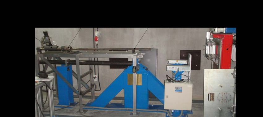
Appl. Sci. 2020, 10, 6108                                                                              2 of 12

and a tensile modulus quite similar to that of aramid fibres [14]. Moreover, fibres with higher cellulose
content, higher degrees of polymerisation and lower microfibrillar angles exhibit higher tensile
strength and moduli [15]. On the other hand, the main disadvantages are their lower thermal stability,
which limits their use with some thermoplastics, and low resistance to moisture and dimensional
stability, which can lead to debonding and microcracking in the composite [16].
      However, there is real evidence that forests in developed countries are dwindling and other natural
products are emerging, especially those obtained from agricultural by-products or agro-waste materials.
In this context, the different cork wastes resulting from the manufacture of various cork-based products
are very attractive because they maintain the same intrinsic characteristics of cork, such as low specific
weight, great elasticity, flexibility and durability, specific stiffness and strength, impermeability to
liquid and gases, resistance to wear and fire, dimensional stability and resistance to reactive agents
and microorganisms [17–20]. These cork wastes present different densities, amounts of moisture,
granulometries, sizes, levels of ash content and tannin concentrations [21,22], and all of them were
conveniently characterized by Gil [23]. For example, cork powder is the most important waste from cork
processing, where only the cork-stopper production is responsible for 25% to 30% of the raw material.
According to the Portuguese Standards NP-114 and NP-273, cork powder has dimensions lower than
0.25 mm and there are different types according to their origin: the grinding powder, from granulation
or pre-grinding; the cleaning powder, without impurities; the finishing powder, from cut and sanding
operations; the agglomerated cork panels’ finishing powder; the agglomerated cork stoppers and
disks’ finishing powder; the insulation cork board powder [23,24]. These powders have been used
mainly as combustion fuels (due to its high heating value) [22,23]. A small fraction are also used as
filling agents (to improve the quality of cork-stoppers) [23,24]; in the production of linoleum [23,24];
in applications in agglomerates [23,24]; as briquettes [23,24]; as agricultural substrates [23,24]; and more
recently, cork powders have been used as pollutant adsorbents or as absorbents in oil splits due to
their good adsorption properties [24–26], and in the production of composites due to their physical
and mechanical properties [27,28].
      Sanchez-Saez et al. [29] developed an experimental study, where the multi-impact behaviour of
agglomerated-cork specimens was analysed. They observed a great capability of agglomerated cork to
absorb energy even after several consecutive impacts. The damage resistance of sandwich structures
with agglomerated cork core and flax/epoxy laminates face sheets subjected to low- and high-velocity
impacts was evaluated by Sarasini et al. [30]. They observed that cork cell walls experienced buckling,
and in this context, the energy absorption at high strains can be quite considerable without signs
of cell walls breakage. This suggest an almost complete recovery of their original shape and size.
Moreover, the composite structures during its service life can be damaged due to impact loading,
and this damage in composite material is of primary concern because it leads to large reduction in
strength and compromises their structural integrity [30,31].
      Reis et al. [32], for example, developed studies in composites incorporating cork powder, obtained
from industrial by-products, and observed benefits in terms of impact strength and glass transition
temperature (Tg ). When 2.5 wt.% was added to the polyester resin, the impact strength increased
to around 18.5% and the Tg to about 7.3% compared to the values obtained with the pristine resin.
In another experimental study [33], these authors obtained benefits in terms of elastic recuperation and
damaged area when cork powder was added to an epoxy resin, and higher penetration threshold and
residual tensile strength of the laminates that incorporate the cork powder. For example, the elastic
recuperation increased by about 26%, for a 21 J impact energy, and the damaged area decreased by
around 15% for the same impact energy and compared to the values obtained for laminates with neat
resin. Regarding the penetration threshold, these values were about 15% while the residual strength
decreased around 47% for laminates subjected to an impact energy of 21 J [33].
      In terms of fatigue properties, independently of the lower static bending strength (around 10%
lower when 3 wt.% of cork powder was added to the resin), Reis et al. [34] observed, based on a
statistical analysis of fatigue data, that fatigue life is insensitive to the presence of cork into the resin.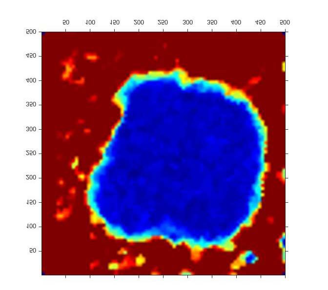
Appl. Sci. 2020, 10, 6108                                                                           3 of 12

Finally, due to the viscoelastic properties of cork and polymeric matrices, Reis et al. [35] performed a
study where the stress relaxation and creep behaviour of multiphase composites incorporating cork
powder were analysed in detail. For this purpose, composites with the same lay-up but with different
fibres were produced. They concluded that higher values of relaxation and creep displacement occur
when Kevlar fibres are used, but, independently of the fibres, higher values were also observed when
cork powder was introduced into the resin.
     Therefore, based on the benefits achieved with this industrial by-product, the main goal of this
work was to study the high-velocity impact behaviour of Kevlar composite laminates filled by cork
powder, in order to obtain full knowledge of all loading modes. These fibres are of particular interest
for military and civilian purposes, due to their high degree of toughness and good impact/ballistic
performance. In fact, aramid fibres fail by a series of small fibril failures that absorb a significant
amount of energy, resulting in very high toughness. For that purpose, this work focused on the
ballistic behaviour and damage tolerance of Kevlar/epoxy reinforced composites, in which the epoxy
matrix is filled with cork powder. The perforation velocity and energy absorption were estimated from
experimental tests and damaged area was obtained by both C-scan ultrasound technique and visual
inspection from impacted specimens. In order to evaluate the damage tolerance, bending after impact
(BAI) tests were carried out.

2. Experimental Procedure
     Composite laminate plates involving Kevlar bi-directional woven fabrics (taffeta with 281 g/cm2 )
and an Ampreg 22 epoxy resin with an Ampreg 22 hardener standard (both supplied by Gurit) were
manufactured with a useful size of 300 × 300 × 3.3 mm3 by hand lay-up technique. For this purpose,
nine ply laminates, all in the same direction, were used. After that, the system was placed inside
a vacuum bag and a load of 2.5 kN was applied for 48 h to ensure a uniform laminate thickness.
During the first 10 h the bag remained attached to a vacuum pump to eliminate possible air bubbles in
the composite laminates. Finally, the post-cure was carried out in an oven at 45 ◦ C for 48 h to guarantee
a convenient curing stage.
     Similar composite laminates with epoxy matrix filled by cork powder were also produced by the
same methodology. The cork powder used consists of a residue obtained during the final sanding
phase of cork-stoppers and it was collected at Amorim Cork S.A. (Valada, Portugal) industrial facilities.
The cork powder presents a particle size, in terms of percentile, of d (0.1) = 18.6 µm, d (0.5) = 78.9 µm
and d (0.9) = 208.3 µm; a bulk density of 0.1095 g.cm−3 ; and a humidity of ≈5.1%. The low moisture
content observed is explained by the fact that the raw material from which the cork powder was
obtained underwent several heating and drying operations [23]. Regardless of the low moisture
content observed, to improve the adhesion with the resin, the cork powder was still dried in an oven
(Heraus, model UT 6060) at 120 ◦ C for 2 h and stored until used in a desiccator. Finally, the cork
powder (3 wt.% of the epoxy resin-hardener mixture) and epoxy resin were mixed at 900 rpm for
2 h, with resource to an electrical mixer, in an ultrasonic bath for an uniform distribution of the cork
particles into the resin. In order to avoid the formation of air bubbles, the mixture was degassed in a
vacuum oven, followed by addition of hardener agent. However, more details about the cork fraction
used and respective manufacturing process can be found in [32–34].
     According to Pintor et al. [24], cork’s structure is formed by hollow polyhedral prismatic cells,
which have a honeycomb shape when observed from the radial direction and rectangular when
observed from the transversal direction [9]. The area of the prism base is 4 to 6 × 10⁻⁶ cm2 , with a mean
prism edge of 13–15 µm and a prim height of 30–40 µm. The mean cell volume is around 2 × 10⁻⁸ cm3
and the number of cells per unit is 4 to 7 × 107 cm−3 . The cell walls are thin, with a thickness of 1 to
1.5 µm, in which is concentrated the solid mass volume fraction of the cork [36]. The cork powder
keeps the same cellular structure intact; however, when the size of cork particles deceases, the number
of closed cells decreases and the external surface areas of the particles increase, and consequently,
the number of open through-cut cells increases [36]. Based in studies reported by Pereira [36], a cork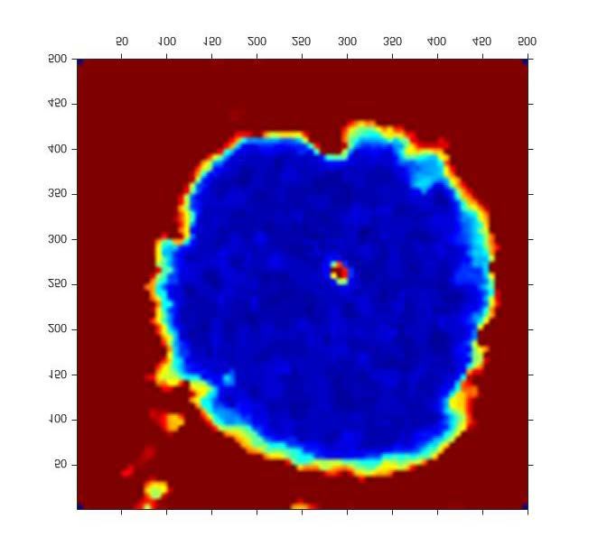
Appl. Sci. 2020, 10, 6108 4 of 12
particle of volume 0.015 mm3 (around 0.25 × 0.25 × 0.25 mm3 ) contains about 500 cells (7–9 cell per
one row) in2020,
Appl. Sci. which
10, x only a fraction
FOR PEER REVIEW of 6 to 8 cells in one row are closed. This evidence and respective 4 of 13
particle shape and morphology are well reported by scanning electron micrographs, in a review paper
particle
compiled byshape
Pereira and morphology
[36], are well similar
for cork particles reportedtobythose
scanning
usedelectron micrographs, in a review
in this study.
paper compiled by Pereira [36], for cork particles similar to those used in this study.
The high-velocity impacts were carried out on plates of Kevlar bi-directional woven laminates
The high-velocity impacts were carried out on plates of Kevlar bi-directional woven laminates
with surface of 100 × 100 mm2 . 2The specimen’s size was big enough that the damaged area did not
with surface of 100 × 100 mm . The specimen’s size was big enough that the damaged area did not
reachreach
the border
the borderof the laminate.
of the laminate.The
Theprojectile usedfor
projectile used forimpact
impact tests
tests waswas of steel
of steel withwith a spherical
a spherical
geometry of 7.5 3
geometry ofmm7.5 mmdiameter
diameterandand
a density
a densityof of
7800
7800kg/m
kg/m.3.InInorder
order to
to carry out the
carry out theimpact
impacttests,
tests,a a gas
gas gun (Figure
gun (Figure 1) was 1) was to
used used to impulse
impulse the projectile
the projectile at at
thetherequired
requiredvelocity.
velocity. This
Thisgas
gasgungunconsists
consists of
of several
several clearlyclearly differentiated
differentiated zones:
zones: thethe loadand
load andaccommodation
accommodation area areaofof
thethe
projectile, the pressure
projectile, the pressure
chamber that impulses the projectile against the target, a launch tube and a frame where
chamber that impulses the projectile against the target, a launch tube and a frame where the laminate the laminate
is embedded.
is embedded.
Figure
Figure 1. Photoofofthe
1. Photo theequipment
equipment used
usedininthe
thehigh-velocity
high-velocityimpact tests.
impact tests.
To impulse
To impulse the projectile,
the projectile, thethe pressure
pressure ofof
thethe gasused
gas usedwas wasregulated
regulated and
and two
twodifferent
differenttypes
typesofof gas
gas were used: helium to achieve the highest velocities, and ® Stargon® a mixture of argon, carbon
were used: helium to achieve the highest velocities, and Stargon a mixture of argon, carbon dioxide and
dioxide and oxygen manufactured by NIPPON GASES ESPAÑA, S.L.U. (Madrid, Spain) for the
oxygen manufactured by NIPPON GASES ESPAÑA, S.L.U. (Madrid, Spain) for the lowest velocities.
lowest velocities.
The The
impactimpacttests were
tests wererecorded
recordedwith
withaa high-velocity camera
high-velocity camera (Figure
(Figure 2), 2), which
which was was
usedused
to pickto pick
up essential information
up essential information such
such asasthe
theimpact
impact and residualvelocities.
and residual velocities.TheThe camera
camera usedused
was was a Photron
a Photron
Fastcam
Fastcam ATX, ATX,
which which is able
is able totoreach
reach250,000
250,000 frames
frames perpersecond.
second.InIn these tests
these the the
tests acquisition data data
acquisition
velocity
velocity waswas 90,00090,000
fps.fps.
TheThe camerawas
camera wasplaced
placed parallel
parallel totothe
theframe
frame of of
essays. An An
essays. ARRI ARRISON
ARRI ARRISON
12 PLUS
12 PLUS
Appl. lamp
Sci. lamp10, was
was
2020, FORused
x used forfor
PEER lighting.This
lighting.
REVIEW Thislamp
lamp has
has aapower
powerofof12001200W.W. 5 of 13
After the impact tests, non-destructive testing (NDT) was carried out on all impacted specimens,
in order to evaluate the damage extension by ultrasonic inspection, specifically C-scan. For this
purpose, the air-coupled scan technique was used, because it is a good alternative to the traditional
ultrasonic immersion C-scan technique when the detection of small defects (matrix cracking,
fibre/matrix interface debonding, etc.) is not required, as in the present study [37,38]. Therefore, a
pair of transducers with 400 kHz centre frequency, 38 mm focus and 25 mm active diameter were
used in a through-transmission configuration.
Figure
Figure 2. 2.Photo
Photoof
ofthe
the high-velocity
high-velocity impact
impacttest setup.
test setup.
Finally, residual strength was obtained by three-point bending (3PB) static tests performed with
a spam of 80 mm in a Shimadzu AG-10 (Riverwood Drive Columbia, SC, USA) universal testing
machine equipped with a 5 kN load cell, strain rate of 5 mm/s and at room temperature.
3. Results and Discussion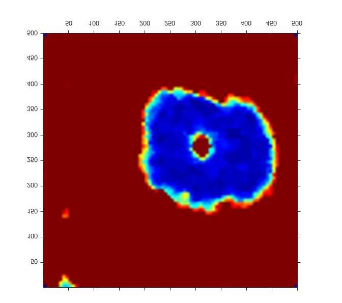
Appl. Sci. 2020, 10, 6108 5 of 12
After the impact tests, non-destructive testing (NDT) was carried out on all impacted specimens,
in order to evaluate the damage extension by ultrasonic inspection, specifically C-scan. For this purpose,
the air-coupled scan technique was used, because it is a good alternative to the traditional ultrasonic
immersion C-scan technique when the detection of small defects (matrix cracking, fibre/matrix
interface debonding, etc.) is not required, as in the present study [37,38]. Therefore, a pair of
transducers with 400 kHz centre frequency, 38 mm focus and 25 mm active diameter were used
in a through-transmission configuration.
Finally, residual strength was obtained by three-point bending (3PB) static tests performed with a
spam of 80 mm in a Shimadzu AG-10 (Riverwood Drive Columbia, SC, USA) universal testing machine
equipped with a 5 kN load cell, strain rate of 5 mm/s and at room temperature.
3. Results and Discussion
Figure 3 shows the absorbed energy regarding impact energy for all the specimens. The variation
of the absorbed energy with impact energy is very similar for both type of plates. Below perforation,
the plates absorb all the kinetic energy of the projectile, mainly by damage. When the impact energy
increases above
Appl. perforation,
Sci. 2020, 10, x FOR PEERthe absorbed energy decreases asymptotically.
REVIEW 6 of 13
Figure
Figure 3. 3. Impactenergy
Impact energy vs.
vs.absorbed
absorbedvelocity.
velocity.
Therefore,
It was not the to
possible minimum
calculatevelocity of perforation
the minimum is about 206.35
perforation ± 4.20inm/s
velocity for Kevlar laminates
a determinist manner, as an
with neat resin, while for that with resin filled with cork powder is around 209.71 ± 4.63 m/s.
impact-velocity interval exists in which the structure may or may not be entirely perforated. In addition,
Regardless of the small difference in terms of average values (1.6%), both values are similar because
the residual velocity of the projectile from the gas gun cannot be fully controlled. For this reason,
they are within the experimental dispersion. In fact, cork is a hydrophobic material with a surface
a high level of scatter
energy of 18 mN.mwas−1, found in typical
while the the data obtained
cured epoxiesfrom
have the experimental
surface tests45around
energy of about mN.m−1the andminimum
a
poor velocity.
perforation adhesion occurs
To obtain for substrates with a least-squares
this velocity, surface energy of 30 mN.m
method wasor
−1 lower.
used, byHowever, this
fitting Equation (1)
which isweakness
similar is
to countered
that proposed by theinlarger externalofsurfaces
the model Recht andof the particles
Ipson [39]. [36].
This Regardless
method has of the
been used
improvements
successfully obtained
to predict the minimumin terms of surface energy
perforation using surface
velocity treatments
in laminate [43,44], Barbosa
and sandwich et al. [44]
structures subjected
report that some of them destroy part of the honeycomb structure of the cork cells (erosion of cork
to high velocity impacts [30,40–42].
cell walls). In this case, the damage caused to the particles can facilitate the penetration of the resin
with the consequent decrease on the absorption of energy, because the damping effect of cork is lost.
Therefore, while the bonds that occur when 0the i f 0 ≤ vi vbl morphology promotes the
weaker,
p the particles’
physical bonds with the penetration of the epoxy resin into the open cells and consequent mechanical
where: interlocking. In this context, the cork particles are surrounded by resin, and the closed cells that
vr is the residual velocity, vi the impact velocity, vbl the minimum velocity of perforation and p
contain air inside can deform when they suffer an impact force and absorb that impact [44]. For this
and A are fitting parameters.
reason, small particles show less improvement than larger particles, because the number of open
Therefore,
through-cutthecells
minimum velocity
increases, and theofresin
perforation
does notisallow
about the206.35 ± 4.20 m/s for
cell deformation. Kevlar laminates
Consequently, they with
cannot
neat resin, absorb
while for as much
that withenergy.
resinTherefore,
filled withthecork
response of the
powder iscork/resin composite
around 209.71 is influenced
± 4.63 by
m/s. Regardless of
the number of closed cells in the particle [44].
In addition to the benefit obtained in terms of impact, it is unquestionable that the cork powder
reduces the amount of resin in the composite, making it more environmentally friendly. These results
are in good agreement with the open literature, where Reis et al. [34] observed, for example, that
fatigue life is insensitive to the presence of cork powder into the resin. Simultaneously, these authors
obtained benefits in terms of impact strength and glass transition temperature [32,33].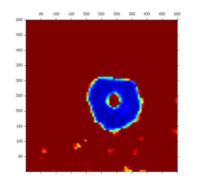
Appl. Sci. 2020, 10, 6108                                                                                         6 of 12

the small difference in terms of average values (1.6%), both values are similar because they are within
the experimental dispersion. In fact, cork is a hydrophobic material with a surface energy of 18 mN.m−1 ,
while the typical cured epoxies have surface energy of about 45 mN.m−1 and a poor adhesion occurs
for substrates with a surface energy of 30 mN.m−1 or lower. However, this weakness is countered by
the larger external surfaces of the particles [36]. Regardless of the improvements obtained in terms of
surface energy using surface treatments [43,44], Barbosa et al. [44] report that some of them destroy
part of the honeycomb structure of the cork cells (erosion of cork cell walls). In this case, the damage
caused to the particles can facilitate the penetration of the resin with the consequent decrease on the
absorption of energy, because the damping effect of cork is lost. Therefore, while the bonds that occur
when the adhesive diffuses into cell walls to build chemical bonds with the cell’s chemical components
are weaker, the particles’ morphology promotes the physical bonds with the penetration of the epoxy
resin into the open cells and consequent mechanical interlocking. In this context, the cork particles are
surrounded by resin, and the closed cells that contain air inside can deform when they suffer an impact
force and absorb that impact [44]. For this reason, small particles show less improvement than larger
particles, because the number of open through-cut cells increases, and the resin does not allow the
cell deformation. Consequently, they cannot absorb as much energy. Therefore, the response of the
cork/resin composite is influenced by the number of closed cells in the particle [44]
       In addition to the benefit obtained in terms of impact, it is unquestionable that the cork powder
reduces the amount of resin in the composite, making it more environmentally friendly. These results
are in good agreement with the open literature, where Reis et al. [34] observed, for example, that fatigue
life is insensitive to the presence of cork powder into the resin. Simultaneously, these authors obtained
benefits in terms of impact strength and glass transition temperature [32,33].
       To understand these results, the failure mechanisms are shown in detail and Figures 4 and 5.
They show typical images obtained from visual inspection for the back side of the plates. Figure 4
shows the specimens of Kevlar and Kevlar with cork powder impacted at similar velocities, close to
      Appl. Sci. 2020, 10, x FOR PEER REVIEW                                                    7 of 13
the perforation velocity, while the specimens of Figure 5 were impacted at higher velocities.

                                      (a)                                      (b)
          Figure
      Figure     4. Damage
             4. Damage       area
                          area of of
                                   thethe backside.
                                        back   side.(a)
                                                     (a) Specimen
                                                         Specimen of
                                                                  ofKevlar
                                                                     Kevlarimpacted
                                                                            impactedat 231 m/sm/s
                                                                                       at 231  andand
                                                                                                   (b) specimen
                                                                                                       (b) specimen
          of Kevlar
      of Kevlar     + cork
                + cork     powder
                        powder      impactedatat230
                                  impacted        230m/s.
                                                       m/s.

     From the visual inspections of the back sides of the plates (Figures 4 and 5), it is visible that the
failure mechanisms are: fibre failure and delamination. Although matrix cracking is not possible to
identify by visual inspection, this is one of the first damage mechanisms in composite laminates, and
therefore, it should appear since it induces other failures modes, as delamination [45].
     The images of the damaged area that were obtained by C-scan in the samples subjected to
different impact velocities are shown in Figures 6 and 7. The impact velocities coincide with the impact
velocities of the samples showed in Figures 4 and 5. In all specimens inspected by C-scan, it was
possible to observe that the damaged areas had circular shapes, a behaviour that also appears in woven
glass laminates [46].

                                       (a)                                    (b)
           Figure 5. Image of damage area of the back side. (a) Specimen of Kevlar impact to 438 m/s and (b)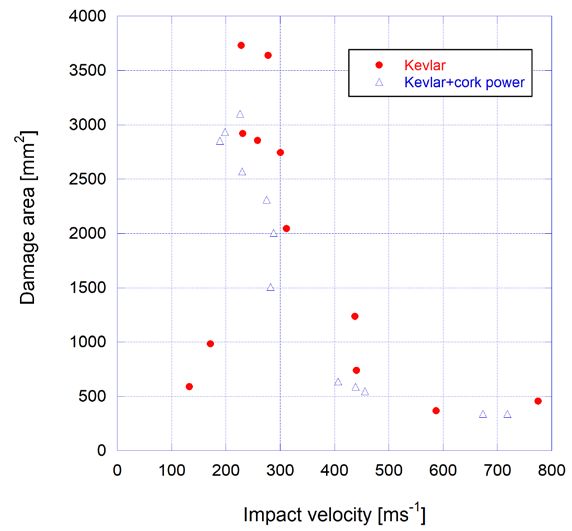
(a) (b)
Figure 4. Damage area of the back side. (a) Specimen of Kevlar impacted at 231 m/s and (b) specimen
Appl. Sci. 2020, 10, 6108 7 of 12
of Kevlar + cork powder impacted at 230 m/s.
(a) (b)
Appl. Sci. 2020, 10, x FOR PEER REVIEW 8 of 13
Appl.Figure
Sci. 2020,
5.10, x FORofPEER
Image REVIEW
damage areaofofthe
theback
back side.
side. (a) 8 of 13
Figure 5. Image of damage area (a)Specimen
Specimenofof
Kevlar impact
Kevlar to 438
impact m/s m/s
to 438 and and
(b) (b)
specimen
specimen of Kevlar
of Kevlar + cork
+ cork powderimpacted
powder impacted to
to 439
439 m/s.
m/s.
From the visual inspections of the back sides of the plates (Figures 4 and 5), it is visible that the
failure mechanisms are: fibre failuremm²
2918.31 and delamination. Although matrix cracking is notmm²
2571.03 possible to
2918.31 mm²
identify by visual inspection, this is one of the first damage mechanisms in composite
2571.03 laminates,
mm² and
therefore, it should appear since it induces other failures modes, as delamination [45].
The images of the damaged area that were obtained by C-scan in the samples subjected to
different impact velocities are shown in Figures 6 and 7. The impact velocities coincide with the
impact velocities of the samples showed in Figures 4 and 5. In all specimens inspected by C-scan, it
was possible to observe that the damaged areas had circular shapes, a behaviour that also appears in
woven glass laminates [46].
(a) (b)
(a) (b)
Figure 6. Images of damage areas by C-scan. (a) Specimen of Kevlar impact to 231 m/s and (b)
FigureFigure 6. of
specimen Images
6. Images of+ damage
Kevlar
of damagecorkareasareas
powder by C-scan.
impacted
by C-scan. (a) m/s.
Specimen
toSpecimen
(a) 230 of Kevlar
of Kevlar impact
impact to m/s
to 231 231 and
m/s (b)
andspecimen
(b)
specimen
of Kevlar of Kevlar
+ cork powder + cork powder
impacted toimpacted
230 m/s.to 230 m/s.
629.81 mm²
1235.87 mm² 629.81 mm²
1235.87 mm²
41.52 mm²
41.52 mm²
(a) (b)
(a) (b)
FigureFigure 7. Images
7. Images of damage
of damage areasareas by C-scan.
by C-scan. (a) Specimen
(a) Specimen of Kevlar
of Kevlar impact
impact to m/s
to 438 438 and
m/s (b)
andspecimen
(b)
Figure 7. of
specimen Images
Kevlarof+ damage areasimpacted
cork powder by C-scan. (a) m/s.
to 439 Specimen of Kevlar impact to 438 m/s and (b)
of Kevlar + cork
specimen powder
of Kevlar impacted
+ cork powder toimpacted
439 m/s.to 439 m/s.
The specimens impacted at higher velocities, around 300 m/s, showed fibre breakage close to the
The
impact specimens
point, impacted
as reported at higher
in Figures velocities,
5 and around 300 the
7. Simultaneously, m/s,C-scan
showed fibre clearly
images breakage close
show to the
that the
impact
damage caused by the bullets not only causes local damage (macro damage), but also affects the
point, as reported in Figures 5 and 7. Simultaneously, the C-scan images clearly show that the
damage caused
vicinity of by the bullets
the damaged not only
areas clearly seencauses local colours
in different damage(micro
(macro damage),
damage), but also
which affects
agrees with the
the
vicinity of the damaged areas clearly seen in different colours (micro damage), which agrees
studies developed by Dhakal et al. [47]. Moreover, the extension of damage is more located around with the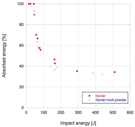
Appl. Sci. 2020, 10, 6108 8 of 12
The specimens impacted at higher velocities, around 300 m/s, showed fibre breakage close to the
impact point, as reported in Figures 5 and 7. Simultaneously, the C-scan images clearly show that
the damage caused by the bullets not only causes local damage (macro damage), but also affects the
vicinity of the damaged areas clearly seen in different colours (micro damage), which agrees with the
studies developed by Dhakal et al. [47]. Moreover, the extension of damage is more located around the
impact point at higher velocities, as can be seen in Figure 7. In this context, the extension of damage
Appl. Sci. 2020, 10,
area determined byx FOR PEER REVIEW
the C-scan 9 of 13
inspection is larger than the damage established by the visual inspection
on both sides of the laminate (front and back face).Therefore, in addition to macro-damage, it is evident
it is evident that the impact also induces internal micro-damage that is not visible to the naked eye,
that the impact also induces internal micro-damage that is not visible to the naked eye, but should be
but should be considered when quantifying the damage size [47].
considered when quantifying the damage size [47].
Figure 8 shows the extension of damage area for all specimens measured by C-scan. In all
Figure 8 shows
structures, the damaged
the larger extensionarea
of damage
was found area
for for all specimens
velocities measured
around the minimumbyperforation
C-scan. In all
velocity. For velocities below the minimum perforation velocity, the damaged area increases with
structures, the larger damaged area was found for velocities around the minimum perforation velocity.
velocity, while for velocities greater than the perforation velocity, the damaged area decreases withwhile
For velocities below the minimum perforation velocity, the damaged area increases with velocity,
increasinggreater
for velocities velocity.than the perforation velocity, the damaged area decreases with increasing velocity.
Figure
Figure 8.8.Extension
Extension of
of damage
damage area
areameasured
measuredbyby
C-scan.
C-scan.
ThisThis behaviour
behaviour was was observedby
observed byBuitrago
Buitrago etet al.
al. [48]
[48]for
forglass woven
glass woven laminates,
laminates, and and
it is produced
it is produced
by thebybending
the bending of the
of the plate
plate due
due totothe
thetransverse
transverse wave
wavetravel,
travel,which
which leads to delamination.
leads to delamination. SinceSince
the the
contact time is maximal at the perforation velocity, the distance travelled by the transverse waveisis also
contact time is maximal at the perforation velocity, the distance travelled by the transverse wave
also maximal,
maximal, and thusand the thus the delaminated
delaminated area[46,49].
area is too is too [46,49].
On theOn the other
other hand,hand,
whenwhen the damaged
the damaged areas are
areas are compared between laminates with neat resin and resin filled by cork powder, in all
compared between laminates with neat resin and resin filled by cork powder, in all conditions there is a
conditions there is a clear tendency for the last ones to have smaller damaged areas. For example,
clear tendency for the last ones to have smaller damaged areas. For example, comparing the damaged
comparing the damaged areas shown in Figures 6 and 7, it is possible to observe that for impact
areasvelocities
shown inaround
Figures 2306 m/s,
and they
7, it is
arepossible
around to observe
11.9% lowerthat for impactwith
for laminates velocities aroundHowever,
cork powder. 230 m/s, they
are around 11.9% lower for laminates with cork powder. However, this value
this value was around 45.7% lower for impact velocities of 438 m/s. Nevertheless, for the highest was around 45.7% lower
impact velocities
for impact velocities, theof damaged
438 m/s. areas tend to be similar.
Nevertheless, for the This behaviour
highest impact allows one to affirm
velocities, that there areas
the damaged
tend are changes
to be similar.in the
Thisenergy absorption
behaviour allowsmechanisms,
one to affirm although there are
that there is not much change
changes in the in the ballistic
energy absorption
behaviour (Figure 3). In fact, cork has a high capacity to absorb energy,
mechanisms, although there is not much change in the ballistic behaviour (Figure 3). In fact, cork and as reported above, the has
response of the cork/resin composite is influenced by the number of closed
a high capacity to absorb energy, and as reported above, the response of the cork/resin composite cells in the cork particles.
Sanchez-Saez
is influenced by the et al. [29] observed
number of closed a great
cellscapacity
in the corkto absorb energy
particles. even after several
Sanchez-Saez et al. consecutive
[29] observed a
impacts. In addition, Sarasini et al. [30] observed in their studies that the absorption of energy in high
great capacity to absorb energy even after several consecutive impacts. In addition, Sarasini et al. [30]
deformations can be quite considerable without signs of breaking of the cell walls, because an almost
observed in their studies that the absorption of energy in high deformations can be quite considerable
complete recovery of their original shape and size occurs.
without signs of Figure
Finally, breaking of thethe
9 shows cell walls, bending
residual becausestrength,
an almost complete
where σ is the recovery
average of their original
bending stress forshape
eachoccurs.
and size velocity and σ0 is the average bending stress obtained from the 3PB static tests for each laminate.Appl. Sci. 2020, 10, 6108 9 of 12
Finally, Figure 9 shows the residual bending strength, where σ is the average bending stress for
Appl. Sci.
each 2020, 10,and
velocity x FOR
σ0 PEER
is theREVIEW 10 of 13
average bending stress obtained from the 3PB static tests for each laminate.
Figure
Figure 9.
9. Impact
Impact velocity
velocity vs.
vs. ratio
ratioof
ofbending
bendingstress.
stress.
Regardless
Regardless of of the
thelower
lowerstatic
staticbending
bendingstrength
strength (around
(around 13.7%
13.7% less
less whenwhen 3 wt.%
3 wt.% of cork
of cork powder powder
was
was added to the resin), which agrees with the studies developed by Reis et al. [34], it is possible to
added to the resin), which agrees with the studies developed by Reis et al. [34], it is possible to observe
observe that laminates
that laminates incorporating
incorporating cork powder corkarepowder are less
less sensitive to sensitive to impact
impact velocity thanvelocity
the samples thanwith
the
samples with neat resin. This is explained by the lower damaged areas that were previously reported
neat resin. This is explained by the lower damaged areas that were previously reported for laminates
for
withlaminates with cork
cork powder, duepowder, due to
to the high the high
capacity tocapacity to absorb
absorb energy energy
from the from
fillers.theInfillers. In addition
addition to that,
to that, Barbosa et al. [44] observed that cork particles act like obstacles to crack propagation. This
Barbosa et al. [44] observed that cork particles act like obstacles to crack propagation. This evidence also
evidence also explains the better bending performance obtained for laminates with cork powder. On
explains the better bending performance obtained for laminates with cork powder. On the other hand,
the
andother hand, andofindependently
independently the laminate, itofisthe
alsolaminate, it is the
evident that alsomaximum
evident that the maximum
bending bending
strength decreases
strength decreases for velocities below the minimum perforation velocity, and that there is a tendency
for velocities below the minimum perforation velocity, and that there is a tendency for it to remain
for it to remain constant for velocities greater than the perforation velocity. However, the observed
constant for velocities greater than the perforation velocity. However, the observed decrease was more
decrease
expressive wasformore expressive
laminates for laminates
with neat resin due with
to theneat resindamage
greater due to the greater
areas observeddamage areas observed
(as reported above).
(as reported above).
4. Conclusions
4. Conclusions
The high-velocity impact and post impact behaviours of Kevlar/epoxy composites, in which the
epoxy matrix
The is filled with
high-velocity cork
impact powder,
and have been
post impact studied.of Kevlar/epoxy composites, in which the
behaviours
In terms of average values, the minimum velocity
epoxy matrix is filled with cork powder, have been studied. of perforation was 1.6% higher for laminates
withIn cork powder,
terms but this
of average difference
values, can be velocity
the minimum neglectedof in view of the
perforation wasdispersion
1.6% higher obtained in the
for laminates
experimental tests. The damage areas increase for velocities below the minimum
with cork powder, but this difference can be neglected in view of the dispersion obtained in the perforation velocity,
but the opposite
experimental trend
tests. Theoccurs for areas
damage velocities greater
increase forthan the perforation
velocities below thevelocity.
minimum However, regardless
perforation the
velocity,
impact
but velocity, the
the opposite C-scan
trend images
occurs reveal that
for velocities lesserthan
greater damage areas are obtained
the perforation velocity.for laminatesregardless
However, with cork
powder, especially for impact velocities close to perforation velocity. Consequently,
the impact velocity, the C-scan images reveal that lesser damage areas are obtained for laminates considering the
residual bending strength, these laminates are less sensitive to impact velocity
with cork powder, especially for impact velocities close to perforation velocity. Consequently,than the samples with
neat resin. In
considering addition
the residualtobending
these benefits,
strength,cork powder
these reduces
laminates are the
lessamount
sensitiveoftoresin in the
impact composite,
velocity than
the samples with neat resin. In addition to these benefits, cork powder reduces the amountwith
making it more environmentally friendly. Finally, in addition to these benefits, laminates cork
of resin
powder
in are more environmentally
the composite, making it more friendly due to their
environmentally lower percentages
friendly. by weight
Finally, in addition to of resin.
these benefits,
laminates with cork powder are more environmentally friendly due to their lower percentages by
weight of resin.
Author Contributions: A.M.A. performed the NDT tests, analysed the results and helped to write the
manuscript; P.N.B.R. produced the laminates and helped to write the manuscript. I.I., S.S.-S., S.K.G.-C. and E.B.Appl. Sci. 2020, 10, 6108 10 of 12
Author Contributions: A.M.A. performed the NDT tests, analysed the results and helped to write the manuscript;
P.N.B.R. produced the laminates and helped to write the manuscript. I.I., S.S.-S., S.K.G.-C. and E.B. carried out the
high-velocity impact tests; contributed in the acquisition, analysis and interpretation of data; and helped to write
the manuscript. All authors have read and agreed to the published version of the manuscript.
Funding: The authors are indebted to the Ministerio de Economía y Competitividad de España for the funds
received for this work within the framework of the project DPI2017-86324-R. This research is sponsored by FEDER
funds through the program COMPETE—Programa Operacional Factores de Competitividade—and by national
funds through FCT—Fundação para a Ciência e a Tecnologia, under the project UIDB/00285/2020.
Conflicts of Interest: Authors declare no conflict of interest.
References
1. Zanjani, N.A.; Wang, W.; Kalyanasundaram, S. The effect of fiber orientation on the formability and failure
behavior of a woven self-reinforced composite. J. Manuf. Sci. Eng. 2015, 137, 051012. [CrossRef]
2. Gholampour, T.; Ozbakkaloglu, A. A review of natural fiber composites: Properties, modification and
processing techniques, characterization, applications. J. Mater. Sci. 2020, 55, 829–892. [CrossRef]
3. Vijayana, R.; Krishnamoorthy, A. Review on natural fiber reinforced composites. Mater. Today Proc. 2019, 16,
897–906. [CrossRef]
4. Elanchezhian, C.; Ramnath, B.V.; Ramakrishnan, G.; Rajendrakumar, M.; Naveenkumar, V.;
Saravanakumar, M.K. Review on mechanical properties of natural fiber composites. Mater. Today Proc. 2018,
5, 1785–1790. [CrossRef]
5. Mohammed, L.; Ansari, M.N.M.; Pua, G.; Jawaid, M.; Islam, M.S. A Review on natural fiber reinforced
polymer composite and its applications. Int. J. Polym. Sci. 2015, 2015, 243947. [CrossRef]
6. Peças, P.; Carvalho, H.; Hafiz Salman, H.; Leite, M. Natural fibre composites and their applications: A review.
J. Compos. Sci. 2018, 2, 66. [CrossRef]
7. Chauhan, V.; Kärki, T.; Varis, J. Review of natural fiber-reinforced engineering plastic composites, their
applications in the transportation sector and processing techniques. J. Thermoplast. Compos. Mater. 2019.
[CrossRef]
8. Thomason, J.L.; Rudeiros-Fernández, J.L. A Review of the impact performance of natural fibre thermoplastic
composites. Front. Mater. 2018. [CrossRef]
9. Pickering, K.L.; Efendy, M.G.A.; Le, T.M. A review of recent developments in natural fibre composites and
their mechanical performance. Compos. Part A Appl. Sci. Manuf. 2016, 83, 98–112. [CrossRef]
10. Nuthong, W.; Uawongsuwan, P.; Pivsa-Art, W.; Hamada, H. Impact property of flexible epoxy treated natural
fiber reinforced PLA composites. Energy Procedia 2013, 34, 839–847. [CrossRef]
11. Saheb, D.N.; Jog, J.P. Natural fiber polymer composites: A review. Adv. Polym. Technol. 1999, 18, 351–363.
[CrossRef]
12. Folkes, M.J. Short Fiber Reinforced Thermoplastic Composites; John Wiley and Sons: New York, NY, USA, 1982.
13. Bledzki, A.K.; Gassan, J. Natural fiber reinforced plastics. In Handbook of Engineering Polymeric Materials;
Marcel Dekker, Inc.: New York, NY, USA, 1997; pp. 787–810.
14. Joseph, P.V.; Joseph, K.; Thomas, S. Effect of processing variables on the mechanical properties of
sisal-fiber-reinforced polypropylene composites. Compos. Sci. Technol. 1999, 59, 1625–1640. [CrossRef]
15. Jayaraman, K. Manufacturing sisal-polypropylene composites with minimum fibre degradation.
Compos. Sci. Technol. 2003, 63, 367–374. [CrossRef]
16. Reis, P.N.B.; Ferreira, J.A.M.; Antunes, F.V.; Costa, J.D.M. Flexural behaviour of hybrid laminated composites.
Compos. Part A Appl. Sci. Manuf. 2007, 38, 1612–1620. [CrossRef]
17. Rosa, M.E.; Fortes, M.A. Deformation and fracture of cork in tension. J. Mater. Sci. 1991, 26, 341–348.
[CrossRef]
18. Rosa, M.E.; Fortes, M.A. Water-absorption by cork. Wood Fiber Sci. 1993, 25, 339–348.
19. Vaz, M.F.; Rosa, M.E. Friction Properties of cork. J. Mater. Sci. 1998, 33, 2087–2093. [CrossRef]
20. Mano, J.F. The viscoelastic properties of cork. J. Mater. Sci. 2002, 37, 257–263. [CrossRef]
21. Mislata, A.M.; Puxeu, M.; Ferrer-Gallego, R. Aromatic potential and bioactivity of cork stoppers and cork
by-products. Foods 2020, 9, 133. [CrossRef]
22. Sepúlveda, F.J.; Arranz, J.I.; Miranda, M.T.; Montero, I.; Rojas, C.V. Drying and pelletizing analysis of waste
from cork granulated industry. Energies 2018, 11, 109. [CrossRef]Appl. Sci. 2020, 10, 6108 11 of 12
23. Gil, L. Cork powder waste: An overview. Biomass Bioenergy 1997, 13, 59–61. [CrossRef]
24. Pintor, A.M.A.; Ferreira, C.I.A.; Pereira, J.C.; Correia, P.; Silva, S.P.; Vilar, V.J.P.; Botelho, C.M.S.;
Boaventura, R.A.R. Use of cork powder and granules for the adsorption of pollutants: A review. Water Res.
2012, 46, 3152–3166. [CrossRef]
25. Pintor, A.M.A.; Vieira, B.R.C.; Boaventura, R.A.R.; Botelho, C.M.S. Removal of antimony from water by
iron-coated cork granulates. Sep. Purif. Technol. 2020, 233, 116020. [CrossRef]
26. Olivella, M.A.; Jové, P.; Oliveras, A. The use of cork waste as a biosorbent for persistent organic
pollutants-study of adsorption/desorption of polycyclic aromatic hydrocarbons. J. Environ. Sci. Health.
Part A 2011, 46, 824–832. [CrossRef]
27. Gil, L. Cork composites: A review. Materials 2009, 2, 776–789. [CrossRef]
28. Fernandes, E.M.; Correlo, V.M.; Chagas, J.A.M.; Mano, J.F.; Reis, R.L. Properties of new cork–polymer
composites: Advantages and drawbacks as compared with commercially available fibreboard materials.
Compos. Struct. 2011, 93, 3120–3129. [CrossRef]
29. Sánchez-Sáez, S.; Barbero, E.; García-Castillo, S.K.; Ivañez, I.; Cirne, J. Experimental response of agglomerated
cork under multi-impact loads. Mater. Lett. 2015, 160, 327–330. [CrossRef]
30. Sarasini, F.; Tirillò, J.; Lampani, L.; Barbero, E.; Sanchez-Saez, S.; Valente, T. Impact behavior of sandwich
structures made of flax/epoxy face sheets and agglomerated cork. J. Nat. Fibers. 2020, 17, 168–188. [CrossRef]
31. Ivañez, I.; Sánchez-Saez, S.; Garcia-Castillo, S.K.; Barbero, E.; Amaro, A.M.; Reis, P.N. Impact response of
repaired sandwich structures. Polym Compos. 2020. [CrossRef]
32. Reis, P.N.B.; Ferreira, J.A.M.; Silva, P.A.A. Mechanical behaviour of composites filled by agro-waste materials.
Fiber. Polym. 2011, 12, 240–246. [CrossRef]
33. Reis, P.N.B.; Ferreira, J.A.M.; Santos, P.; Richardson, M.O.W.; Santos, J.B. Impact response of Kevlar composites
with filled epoxy matrix. Compos. Struct. 2012, 94, 3520–3528. [CrossRef]
34. Reis, P.N.B.; Ferreira, J.A.M.; Costa, J.D.M.; Santos, M.J. Fatigue performance of Kevlar/epoxy composites
with filled matrix by cork powder. Fiber. Polym. 2012, 13, 1292–1299. [CrossRef]
35. Reis, P.N.B.; Silva, M.P.; Santos, P.; Parente, J.M.; Bezazi, A. Viscoelastic behaviour of Composites with Epoxy
Matrix Filled by Cork Powder. Compos. Struct. 2020, 234, 111669. [CrossRef]
36. Pereira, H. The rationale behind cork properties: A review of structure and chemistry. BioResources 2015, 10,
1–23. [CrossRef]
37. Amaro, A.M.; Reis, P.N.B.; Santos, J.B.; Santos, M.J.; Neto, M.A. Effect of the electric current on the impact
fatigue strength of CFRP composites. Compos. Struct. 2017, 182, 191–198. [CrossRef]
38. Santos, M.J.; Santos, J.B.; Reis, P.N.B.; Amaro, A.M. Ultrasonic C-scan techniques for damage evaluation of
carbon fiber reinforced polymers submitted to low energy impacts. Proc. Mtgs. Acoust. 2019, 38, 030002.
39. Recht, R.F.; Ipson, T.W. Ballistic perforation dynamics. J. Appl. Mech. T ASME 1963, 30, 384–390. [CrossRef]
40. García-Castillo, S.K.; Buitrago, B.L.; Barbero, E. Behavior of sandwich structures and spaced plates subjected
to high-velocity impacts. Polym. Compos. 2011, 32, 290–296. [CrossRef]
41. Sánchez-Sáez, S.; Barbero, E.; Cirne, J. Experimental study of agglomerated-cork-cored structures subjected
to ballistic impacts. Mater. Lett. 2011, 65, 2152–2154. [CrossRef]
42. Ivañez, I.; Sánchez-Saez, S.; Garcia-Castillo, S.K.; Barbero, E.; Amaro, A.; Reis, P.N.B. High-velocity impact
behaviour of damaged sandwich plates with agglomerated cork core. Compos. Struct. 2020, 112520. [CrossRef]
43. Abenojar, J.; Barbosa, A.Q.; Ballesteros, Y.; del Real, J.C.; da Silva, L.F.M.; Martinez, M.A. Effect of surface
treatments on natural cork: Surface energy, adhesion, and acoustic insulation. Wood Sci. Technol. 2014, 48,
207–224. [CrossRef]
44. Barbosa, A.Q.; da Silva, L.F.M.; Öchsner, A.; Abenojar, J.; del Real, J.C. Influence of the size and amount of
cork particles on the impact toughness of a structural adhesive. J. Adhes. 2012, 88, 452–470. [CrossRef]
45. Moure, M.M.; Otero, F.; García-Castillo, S.K.; Sánchez-Sáez, S.; Barbero, E.; Barbero, E.J. Damage evolution in
open-hole laminated composite plates subjected to in-plane loads. Compos. Struct. 2015, 133, 1048–1057.
[CrossRef]
46. Gil-Alba, R.; Alonso, L.; Navarro, C.; García-Castillo, S.K. Morphological study of damage evolution in
woven-laminates subjected to high-velocity impact. Mech. Adv. Mater. Struc. 2019, 26, 2023–2029. [CrossRef]
47. Dhakal, H.N.; Zhang, Z.Y.; Bennett, N.; Reis, P.N.B. Low-velocity impact response of non-woven hemp
fibre reinforced unsaturated polyester composites: Influence of impactor geometry and impact velocity.
Compos. Struct. 2012, 94, 2756–2763. [CrossRef]Appl. Sci. 2020, 10, 6108 12 of 12
48. Buitrago, B.L.; García-Castillo, S.K.; Barbero, E. Experimental analysis of perforation of glass/polyester
structures subjected to high-velocity impact. Mater. Lett. 2010, 64, 1052–1054. [CrossRef]
49. García-Castillo, S.K.; Sánchez-Sáez, S.; Barbero, E. Nondimensional analysis of ballistic impact on thin woven
laminate plates. Int. J. Impact Eng. 2012, 39, 8–15. [CrossRef]
© 2020 by the authors. Licensee MDPI, Basel, Switzerland. This article is an open access
article distributed under the terms and conditions of the Creative Commons Attribution
(CC BY) license (http://creativecommons.org/licenses/by/4.0/).You can also read