Transport and assembly manual - Menerga devices - Read the instructions prior to performing any task!
←
→
Page content transcription
If your browser does not render page correctly, please read the page content below
Transport and assembly manual

Menerga devices

                  Read the instructions prior to performing any task!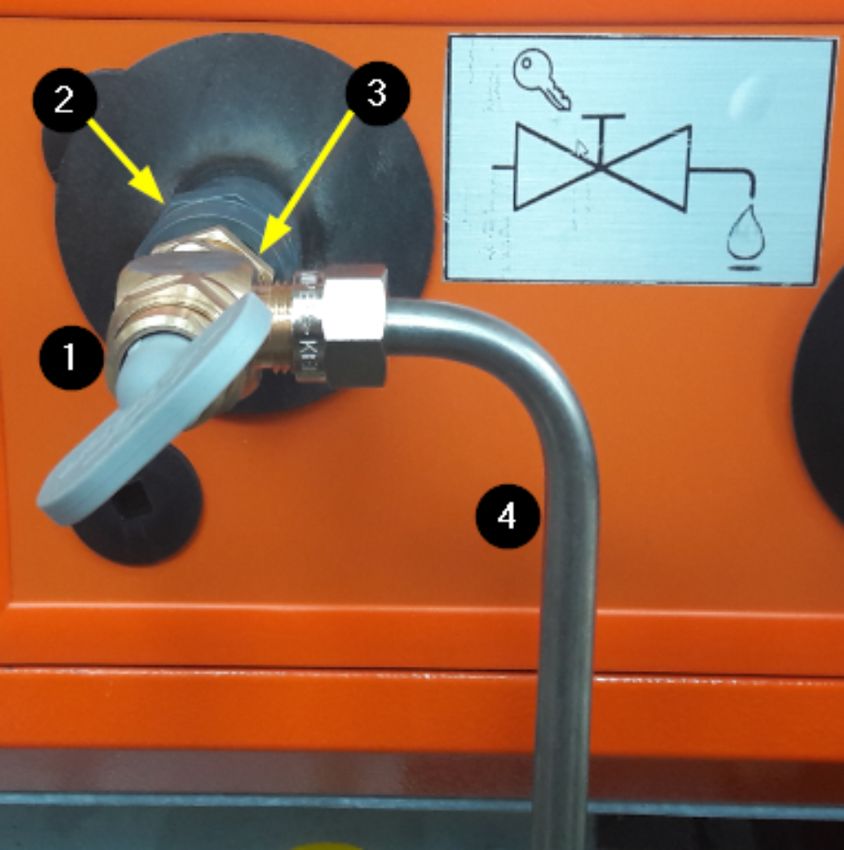
Menerga GmbH
Alexanderstrasse 69
45472 Mülheim an der Ruhr
Telephone: +49 208 9981-0
Fax: +49 208 9981-110
Email: info@menerga.com
Internet: www.menerga.com
Translation of the original
ME-TM-V5-DE, 5, en_GB

© Menerga GmbH 2021

2                             Menerga devices   06.01.2021
Supplemental directives

Scope                     This transport and assembly manual enables you to handle the air-
                          conditioning and water-handling device safely and efficiently (here-
                          inafter referred to as the device).
                          The transport and assembly manual is an integral part of the
                          device and must be kept close to the unit and be accessible for
                          staff at all times.
                          The staff must have carefully read through and understood this
                          transport and assembly manual before starting any work. Adher-
                          ence to all the safety information and instructions specified in this
                          transport and assembly manual is a basic prerequisite in order to
                          ensure safety whilst working.
                          The local regulations for the prevention of accidents and general
                          safety rules for operational area of the device also apply.
                          The illustrations in this transport and assembly manual are for the
                          purpose of basic understanding and may differ from the actual
                          device delivered.

Copyright                 This manual is protected by copyright and intended exclusively for
                          use with the device.
                          The transfer of these instruction to third parties, duplication of any
                          type and form - including excerpts -, and the exploitation and/or
                          communication of the contents are prohibited without written
                          approval from Menerga GmbH except for internal purposes.
                          Any infringement will render the offender liable for compensation.
                          All rights reserved.

Limitation of liability   All the information and instructions in this manual have been com-
                          piled with the utmost care, taking into account the applicable stand-
                          ards and regulations, state-of-the-art technology and our years of
                          knowledge and experience.
                          The manufacturer assumes no liability for damages caused by:
                          n   Failure to adhere to these instructions
                          n   Improper use
                          n   Use of unqualified staff
                          n   Failure to adhere to the recognised rules of technology
                          n   Unauthorised alterations
                          n   Technical modifications to the device
                          The obligations agreed in the contract of supply, the general terms
                          and conditions of business, the manufacturer's terms and condi-
                          tions of supply and the legal regulations valid at the time of com-
                          pletion of the contract apply.

06.01.2021                    Menerga devices                                                      3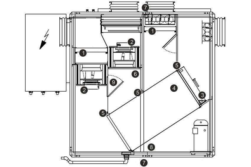
Supplemental directives

Customer service              The Menerga customer service team can be reached at the fol-
                              lowing phone number,

                              Telephone (DE)                     +49 208 9981-199
                              Telephone (GB)                     +44 121322 0258

                              or at the following Internet address: www.menerga.com/de/kontakt.

Applicable documents          The following documents are valid in addition to this transport and
                              assembly manual:
                              n Operating manual
                              n Cooling logbook (optional)
                              n Circuit diagram
                              n Unit drawing
                              n Description of the device division of device series 18/28
                                (optional, included as a separate document with the transport
                                and assembly manual)
                              n Order confirmation

4                                 Menerga devices                                      06.01.2021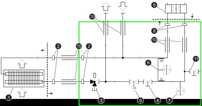
Table of contents

Table of contents
                    1    Safety................................................................................... 7
                         1.1    Explanation of symbols................................................. 7
                         1.2    Responsibility of the operator....................................... 8
                         1.3    Staff requirements....................................................... 10
                         1.4    Personal safety equipment and clothing..................... 11
                    2    Transport and storage...................................................... 13
                         2.1 Delivery.......................................................................     13
                         2.1.1 Type of packaging....................................................             13
                         2.1.2 Symbols on the packaging.......................................                   14
                         2.1.3 Accessories for device installation...........................                    16
                         2.1.4 Checking the delivery..............................................               16
                         2.2 Transporting the transport sections............................                     17
                         2.2.1 Safety notes on transport.........................................                17
                         2.2.2 Transport by means of fork-lift trucks.......................                     19
                         2.2.3 Transport with the crane..........................................                21
                         2.3 Storing transport sections...........................................               27
                         2.4 Unpacking transport sections.....................................                   28
                         2.5 Additional division of transport sections......................                     28
                         2.5.1 Separating/connecting the profile frame..................                         29
                         2.5.2 Dividing the device (device series 18/28)................                         30
                         2.5.3 Dividing the device (device series 19/29)................                         31
                         2.5.4 Dividing the device (device series 38/76)................                         34
                    3    Placement and assembly.................................................                 36
                         3.1 Safety notes on the placement and assembly............                              36
                         3.2 On-site requirements..................................................              36
                         3.2.1 Requirements for indoor and outdoor installation....                              36
                         3.2.2 Additional requirements for outdoor units................                         38
                         3.3 Setting up and assembling device components.........                                38
                         3.3.1 Connecting individual cubes....................................                   38
                         3.3.2 Tightening individual cubes......................................                 44
                         3.3.3 Installing individual cubes above one another.........                            46
                         3.3.4 Recuperator cube with horizontal splits between
                               cubes for device series 54/56/58 from size 25
                               (optional for smaller sizes).......................................               48
                         3.3.5 Assembling device components outdoors...............                              49
                         3.3.6 Assembling the thermal insulation layer..................                         55
                         3.3.7 Assembling the reverse osmosis system.................                            57
                         3.4 After the assembly......................................................            58
                    4    Installation.........................................................................   58
                         4.1 Safety notes on the installation...................................                 58
                         4.2 Connecting the air duct system..................................                    60
                         4.3 Connecting the drainage and overflow pipework........                               61
                         4.4 Connecting the air heater and air cooler.....................                       64

06.01.2021              Menerga devices                                                                           5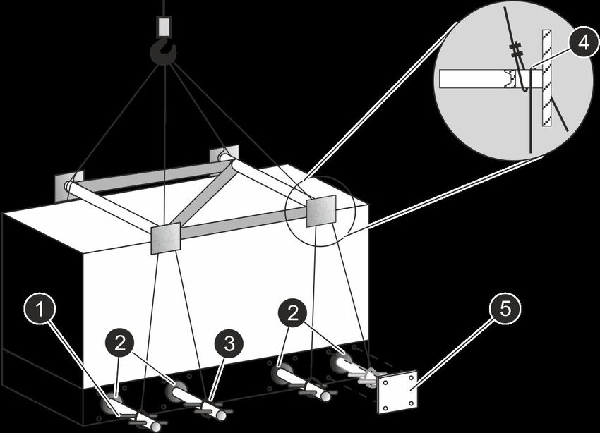
Table of contents

                             4.5 Connecting the pool water condenser........................                        66
                             4.6 Connecting the hot water condenser..........................                       68
                             4.7 Connecting the process water connection..................                          69
                             4.8 Connecting the adiabatic evaporative cooling............                           71
                             4.9 Connecting the sampling valve...................................                   73
                             4.10 Connecting the reverse osmosis system..................                           74
                             4.11 Connecting the building heat pump..........................                       77
                             4.12 Connecting the refrigerant sub-cooler......................                       80
                             4.13 Installing the combined circulation system...............                         81
                             4.14 Connecting the refrigerant lines................................                  84
                             4.15 Connect drainage pipe..............................................               85
                             4.16 Connecting the energy supply..................................                    86
                             4.17 After the installation..................................................          88
                        5    Removal/disassembly and disposal...............................                        89
                             5.1 Safety during the dismantling and disposal................                         89
                             5.2 Removal/disassembly.................................................               92
                             5.3 Disposal......................................................................     93
                        6    Index................................................................................... 94

6                           Menerga devices                                                            06.01.2021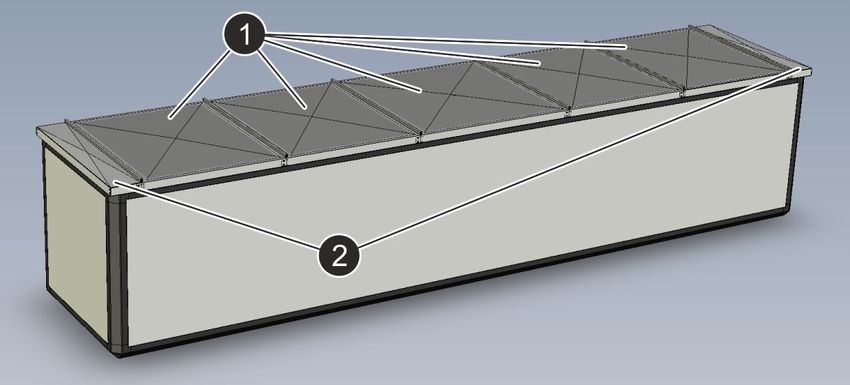
Explanation of symbols

1      Safety
1.1 Explanation of symbols
Safety notes
                                         DANGER!
                                         This combination of symbol and signal word indi-
                                         cates an immediate dangerous situation, leading to
                                         death or serious injury if not avoided.

                                         WARNING!
                                         This combination of symbol and signal word indi-
                                         cates a potentially dangerous situation which may
                                         cause serious or even fatal injuries if not avoided.

                                         CAUTION!
                                         This combination of symbol and signal word indi-
                                         cates a potentially dangerous situation which may
                                         cause minor or light injuries if not avoided.

                                         NOTICE!
                                         This combination of symbol and signal word indi-
                                         cates a potentially dangerous situation which may
                                         cause material damage and environmental
                                         damage if not avoided.

                                         ENVIRONMENT!
                                         This combination of symbol and signal word indi-
                                         cates possible hazards for the environment.

Tips and recommendations
                                         This symbol indicates tips and recommendations
                                         and information for efficient and fault-free opera-
                                         tion.

Special safety instructions   The following symbols are included with safety instructions in order
                              to make you aware of particular hazards:

                              Symbol                             Type of hazard
                                                                 Warning of dangerous electric
                                                                 voltage.

06.01.2021                        Menerga devices                                                      7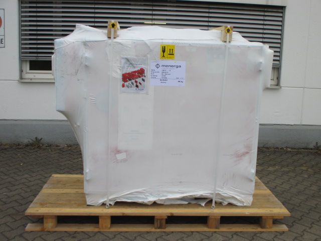
Responsibility of the operator

                                     Symbol                                 Type of hazard
                                                                            Warning of a potential danger.

Signs in this manual                 The following signs and emphases are used in this manual to
                                     denote instructions for use, descriptions of results, bulleted lists
                                     and references to other elements:

                                     Sign                Explanation
                                                         Step-by-step instructions
                                             ð           Results of actions
                                                         References to sections in this manual and
                                                         other valid documents.
                                                         Lists without defined sequence
                                            [Key]        Controls (e.g. button, switch)
                                        ‘Notification’   Screen elements (e.g. buttons, menus, assign-
                                                         ment of function keys)
                                      ‘Menu è Menu’ Menu path

1.2 Responsibility of the operator
User                                 The operator is the person who operates the device himself or her-
                                     self or makes it available to a third party for use/application and is
                                     legally responsible for the protection of the user, staff and third par-
                                     ties during the operation of the product.

User obligations                     The device is used in the commercial or private area. The operator
                                     of the device is subject to the legal obligations for occupational
                                     health and safety.
                                     In addition to the safety notes in these instructions, the regulations
                                     for safety, the prevention of accidents, hygiene and environmental
                                     protection valid for the operational area of the device must be fol-
                                     lowed.
                                     In particular the following applies:
                                     n The operator must clearly regulate and define the responsibili-
                                       ties for transport, placement and assembly, installation, decom-
                                       missioning, disassembly and disposal.
                                     n The required personal protection equipment must be provided
                                       and used for working on the device.
                                     n Maintenance platforms and safety harnesses must be provided
                                       for working on the device at a device height of over 3 m.
                                     n The country-specific statutory provisions must be followed.

8                                        Menerga devices                                         06.01.2021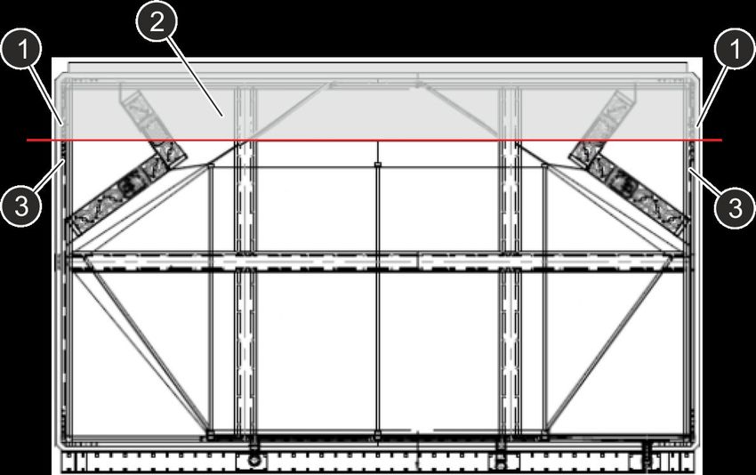
Responsibility of the operator

                                      n Suitable equipment must be provided.
                                      n The device must be properly incorporated into the on-site light-
                                        ning protection concept.
                                      n The device must be properly incorporated into the on-site fire
                                        prevention concept.
                                      n A lightning arrester must be fitted to devices for outdoor instal-
                                        lation.
                                      n Any electrical connections must be carried out by a qualified
                                        electrician.
                                      n All safety devices must be checked regularly to make sure that
                                        they are functional and complete.

Additional obligations of the oper-   The device may only be set up and operated in the explosion pro-
ator when using the device in an      tection area as described on the type plate and the order confirma-
area at risk of explosion             tion and in accordance with the ATEX guideline.
                                      Changes to the device are only to be carried out by qualified per-
                                      sons. After changes are made, a new conformity evaluation must
                                      be carried out in accordance with the ATEX guideline.
                                      The information in the operating manual of the device that causes
                                      the explosion-risk zone is also to be taken into account.
                                      Repairs and work on the electrical equipment may only be carried
                                      out by a specialist for explosion-risk areas or by the manufacturer.
                                      The obligations of the operator also include the following organisa-
                                      tional measures:
                                      n   Labelling of the explosion-risk zones
                                      n   Clear signs regarding all prohibitions
                                      n   Creation of explosion protection documents for every zone
                                      n   Issuing of an access prohibition for unauthorised persons

Additional operator duties when       In accordance with DIN 1946, Part 4, the unit is only authorised for
device is used in the health system   use in buildings and spaces that form part of the health system if
                                      the permit is certified explicitly in the Menerga GmbH order confir-
                                      mation and all hygiene regulations are complied with.

06.01.2021                                Menerga devices                                                         9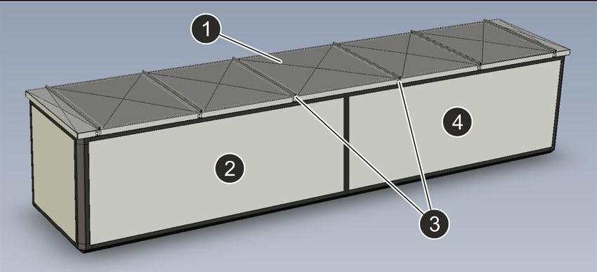
Staff requirements

1.3 Staff requirements

                                    WARNING!
                                    Risk due to inadequately qualified people!
                                    Inadequately qualified people may not appreciate
                                    the risks involved in dealing with the device and
                                    expose themselves and others to the risk of
                                    serious or fatal injury.
                                    –   All works should only be carried out by people
                                        qualified for those tasks.
                                    –   Keep inadequately qualified people away from
                                        the working area.
                                    –   The personnel must be familiar with and must
                                        follow the applicable provisions, hygiene
                                        requirements and permissible working proce-
                                        dures from the health sector.

                         These instructions make reference to the following staff qualifica-
                         tions for the various task areas:

                         Crane operator
                         The crane operator has to be physically and mentally capable of
                         operating a crane system autonomously within its service bounda-
                         ries and to perform maintenance tasks on the crane system.
                         The crane operator has been appropriately trained in operating and
                         maintaining a crane system and has demonstrated these skills to
                         the operator.
                         The crane operator shall reliably undertake the tasks entrusted to
                         them.
                         The crane operator will be assigned their tasks by the operator and
                         must be over 18 years of age.

                         Fork-lift driver
                         The fork-lift operator has to submit evidence to the operator
                         regarding their capability in operating fork-lift trucks, and has sub-
                         sequently been instructed in writing by the operator in accordance
                         with the guide.

                         Refrigeration technician
                         The refrigeration technician is trained and certified for the specific
                         task area in which he works and knows the applicable standards
                         and provisions. The certification includes the necessary compe-
                         tence in emission prevention, recovery of fluorinated greenhouse
                         gases and the safe handling of refrigeration equipment of the rele-
                         vant type and size.
                         The refrigeration technicians can perform works on refrigeration
                         systems due to their training and experience and recognise and
                         avoid possible hazards independently.

10                           Menerga devices                                        06.01.2021
Personal safety equipment and clothing
Skilled electricians
The electricians must be professionally trained in carrying out
works on electrical systems and have a good knowledge of the
pertinent standards and stipulations in order to recognise and
avoid possible dangers independently.
Technicians for sanitary, heating and
air conditioning engineering systems
The technicians for sanitary, heating and air conditioning systems
are trained for the specific task area in which they operate, and
perform their work in compliance with relevant regulations and
safety provisions independently according to documents and
instructions. The technicians for sanitary, heating and air condi-
tioning systems have in-depth knowledge and skills in the field of
air handling technology.
The technicians for sanitary, heating and air conditioning systems
can carry out work on these systems due to their training and
experience and their ability to recognise and avoid possible haz-
ards on their own.
1.4 Personal safety equipment and clothing
Personal safety clothing and equipment is used to protect staff
from hazards which could have an adverse effect on their safety or
health during work.
Staff must wear personal safety equipment and clothing when car-
rying out different types of work on and with the device. The indi-
vidual chapters contain the respective specific references. The fol-
lowing is an explanation of this personal safety equipment and
clothing:
n The personal safety equipment and clothing required in the
various chapters of these instructions must be applied before
performing the respective work.
n Adhere to the signs in the working area regarding personal
safety equipment and clothing.
Description of the personal safety
equipment and clothing
Ear protection
Ear protection is used to protect against hearing loss due to expo-
sure to noise.
Hard hat
Hard hats protect the head against falling objects, swinging loads
and bumping into fixed objects.
06.01.2021 Menerga devices 11Personal safety equipment and clothing
Occupational safety clothing (Personal Protection Equipment
- PPE)
Occupational safety clothing is close-fitting working clothing with
low resistance to tearing, with close-fitting sleeves and no pro-
truding parts.
Protective goggles
The protective goggles are used to protect the eyes from flying
parts and liquid splashes.
Safety gloves
Wear protective gloves to protect your hands from rubbing, abra-
sions, cuts or more severe injuries as well as before touching hot
or cold surfaces.
Safety harness
To reduce risk of falling a safety harness must be used. When cer-
tain heights are exceeded and the working location is not secured
by a railing a safety harness must be worn.
Fit the safety harness so that the safety rope is connected securely
to the fastening points. A shock absorber may also be fitted.
Safety harnesses must only be used by personnel with special
training.
Safety shoes
Safety shoes protect the feet against crushing, falling objects and
slipping on slippery surfaces.
12 Menerga devices 06.01.2021Delivery > Type of packaging
2 Transport and storage
2.1 Delivery
2.1.1 Type of packaging
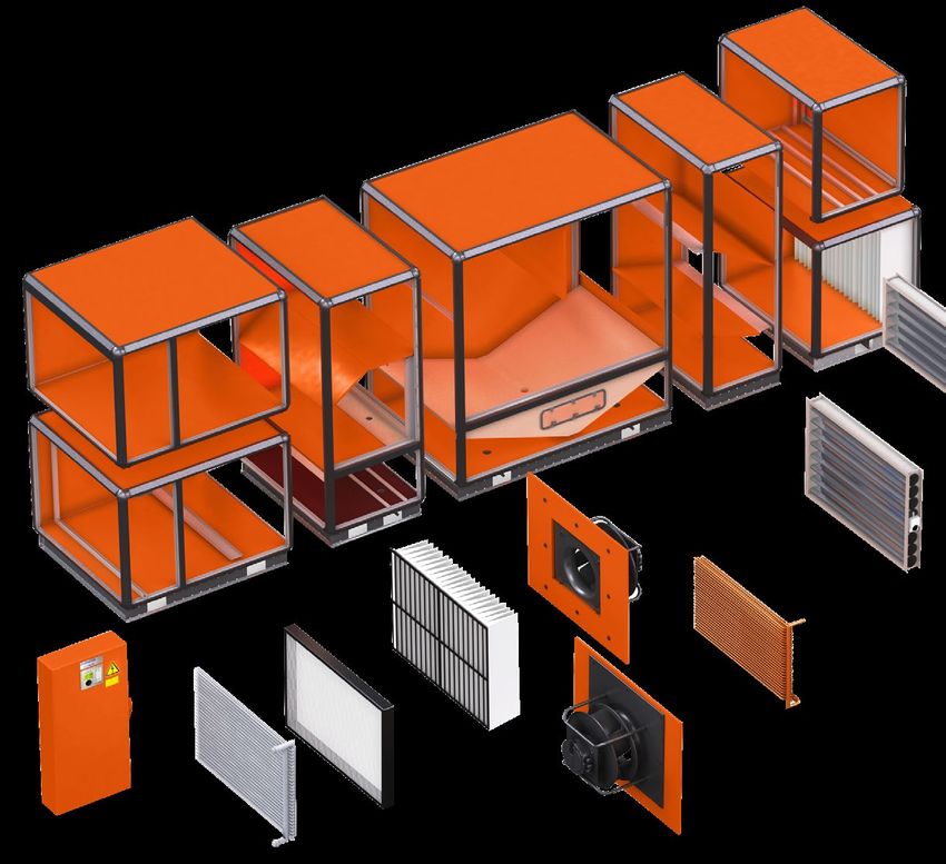
Fig. 1: Type of delivery (example)
The device is delivered divided into several transport sections or a
single piece depending on the size. (Fig. 1). The transport sections
are individually screwed to the base frame or delivered on wooden
pallets and wrapped in film. The wrapping protects the device from
marking during transport, corrosion and other damage. Therefore,
do not destroy the packaging and remove only shortly before
installation.
06.01.2021 Menerga devices 13Delivery > Symbols on the packaging
Fig. 2: Device drawing (example)
1 Cleaning drain (example)
2 Floor drain (example)
3 Condensate drain (example)
The division of the individual cubes of the device can be seen from
the unit drawing (Fig. 2). The transport section in the package is
indicated in the unit drawing with an “X”. In order to connect the
device with the correct terminals for installation, they are labelled in
the unit drawing marked as (Fig. 2/1+2+3). The unit drawing is
fixed to the outside of the transport section and is supplied as a
separate document with the operating manual.
2.1.2 Symbols on the packaging
The following symbols are visible on the packaging and instruc-
tions must be followed during the transportation of the unit sec-
tions.
There may be additional symbols, information and
instructions on the packaging. These must also be
followed.
14 Menerga devices 06.01.2021Delivery > Symbols on the packaging
Lifting points for fork-lift trucks and
lifting pipes
The symbol (Fig. 3) denotes the lifting points of the transport sec-
tion for inserting the forks of the fork-lift truck and for inserting the
lifting pipes to the transport section. If the unit section is marked
with this symbol, then only the lifting points marked with this
symbol may be used for transport (Ä 2.2.2 ‘Transport by means of
fork-lift trucks’ on page 19).
Fig. 3: Lifting points
Lifting points for lifting pipes
The symbol (Fig. 4) denotes the lifting points for the insertion of the
lifting pipes. If the unit section is marked with this symbol, then only
the lifting points marked with this symbol may be used for the
insertion of the lifting pipes. The transport must be fastened to the
lifting pipes (Ä 2.2.3 ‘Transport with the crane’ on page 21).
Fig. 4: Lifting points
Attaching tension belts
The symbol (Fig. 5) marks the points at which tension belts may be
placed on the transport sections while packaged. The attachment
points must be used for securing and fixing the transport units to
the transport vehicle.
Tension straps can be easily damaged by sharp-edged loads. Use
edge protection for this reason. The load is protected and the
forces acting on the belt are transferred in a better manner.
Fig. 5: Attachment points for tension Only use approved and undamaged tension belts.
belts
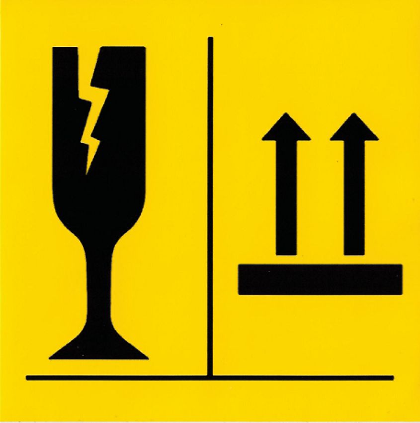
Fragile / top
The symbol (Fig. 6) marks transport units and packages with
fragile or delicate contents. It also marks the upright position of
transport units and packages.
Handle the transport sections and packages carefully; do not let
them fall or subject them to any shocks.
The transport units and packages must always be transported,
handled and stored in such a way that the arrows point upwards at
all times. Rollers, flaps, strong tilting as well as other forms of han-
dling not described herein must be avoided.
Fig. 6: Fragile / top
06.01.2021 Menerga devices 15Delivery > Checking the delivery
2.1.3 Accessories for device installation
The scope of delivery includes accessories which are stored in
separate packaging within the unit. The accessories are listed sep-
arately on the delivery note and are required for device installation.
The sticker (Fig. 7) marks the location at which the accessories are
stored in the device.
Fig. 7: Accessories
2.1.4 Checking the delivery
The delivery must be checked upon receipt and prior to unloading
for completeness and transport damages. Transport damages, or
an incomplete delivery, must be reported immediately to the ship-
ping agent and to Menerga GmbH. Missing parts must be noted on
the waybill and confirmed by the shipping agent making the
delivery.
If there is any transport damage identified, follow the points below:
Packaging is damaged n Photographically document the delivery in its packaged state in
the presence of the shipping agent.
n Unpack the delivery in the presence of the shipping agent and
record the damage on the shipping order.
n Document all damages with photographs and document the
facts in writing.
n Report the damage immediately to Menerga GmbH after identi-
fication.
Contents of the package are dam- n Document all damages with photographs and document the
aged facts in writing.
n Report the damage immediately to Menerga GmbH after identi-
fication.
After the delivery is checked, any opened packaging must be
sealed again.
16 Menerga devices 06.01.2021Transporting the transport sections > Safety notes on transport
2.2 Transporting the transport sections
2.2.1 Safety notes on transport
Improper transport
WARNING!
Fatal hazard due to improper transport!
If sections are moved and transported without
using the devices provided and sections are lifted,
or fall or topple during transport, then danger to life
and substantial material damage could occur.
– Ensure that doors, dampers and panels are
fixed and secured.
– Make sure that the control cabinet mounted on
the device is sufficiently secure and cannot
swing out.
– Vehicles must be designed for the weight of the
transport sections and approved for trans-
porting.
– Do not knot ropes, belts or chains or lay them
on sharp edges.
– Make sure that the ropes cannot twist.
– Fasten to the vehicle using only the designated
fastening points.
– The forks of the fork-lift truck must be longer
than the depth of the transport section.
– Transport sections without marked lifting points
or units with feet must only be lifted from
underneath.
– Ropes, belts or chains may not touch the
device during transport. Use suitable rope
spreaders or upper lifting beams.
– Do not place any pressure on handles, fluid
connections and protruding parts either directly
or indirectly.
– Do not use the transport itself as a means for
permanent device suspension.
– Transport sections may not be stacked.
– Make sure that there are no objects, people or
obstacles in the pivoting range of the transport
section while it is being moved.
– Never stand under suspended loads.
06.01.2021 Menerga devices 17Transporting the transport sections > Safety notes on transport
Off-centre centre of gravity
WARNING!
Risk of injury due to falling or toppling trans-
port sections!
Transport sections may not have a centralised
centre of gravity. If fastened incorrectly, the
package can topple and fall. Falling or toppling
transport sections can cause serious injuries.
– When using a crane to move the sections,
fasten the crane hook in such a way that it is
positioned above the centre of gravity of the
unit.
– Move the forks of the forklift under the
transport section in such a manner that it
cannot tip over.
– Align the means of transport (rope spreaders
and upper lifting beams) to the centre of gravity
for a balanced load distribution.
– Lift the transport sections carefully. If they start
to tilt, then stop the lift and change the fas-
tening.
Ambient temperatures
NOTICE!
Potential damage in extreme temperatures!
The movement of transport sections at high or low
ambient temperatures can cause considerable
damage to the device.
– Only move the transport sections in ambient
temperatures between -20 °C and +45 °C.
Tilting of transport sections
NOTICE!
Damage caused by high or low outdoor temper-
atures!
The tilting of transport sections can cause consid-
erable damage to the transport sections.
– Transport sections may only be tilted if this is
indicated in the unit drawing.
18 Menerga devices 06.01.2021Transporting the transport sections > Transport by means of fork-lift trucks
Mechanical load of the insulation
cover NOTICE!
Damage to property due to the mechanical load
of the insulation cover
The insulation covers that can optionally be
attached to the cubes may be damaged by
mechanical loads during transport.
– Proceed carefully when transporting the cubes.
2.2.2 Transport by means of fork-lift trucks
The transport sections can be transported on wooden pallets or
with the marked lifting points in the device base. Here, only the
marked lifting points may be used for the transport. For transport
sections with feet and without marked lifting points, the forks of the
fork-lift truck must be set below the unit base.
n Ä ‘Transport on a wooden pallet’ on page 19
n Ä ‘Transport using lifting points’ on page 20
Transport on a wooden pallet
Personnel: n Fork-lift driver
Protective equip- n Hard hat
ment: n Safety shoes
n Safety gloves
n Ear protection
n Occupational safety clothing (Personal
Protection Equipment - PPE)
The dimensions, weights and labelling of transport sections can be
taken from the unit drawing.
The unit drawing is fixed to the outside of the transport section of
the unit and can also be found in the operating manual; see
example Ä 2.1.1 ‘Type of packaging’ on page 13.
WARNING!
Risk of injury due to swinging control cabinet!
The pivoting of the control cabinet can cause
serious injuries and significant property damages.
1. For transport sections with assembled pivoting control cab-
inet, secure the control cabinet with tension belts.
06.01.2021 Menerga devices 19Transporting the transport sections > Transport by means of fork-lift trucks
Fig. 8: Pallets
2. Move the forks (Fig. 8/2) of the fork-lift truck apart up to the
cross-beam (Fig. 8/1) of the wooden pallet.
3. Insert the forks of the fork-lift truck all the way under the
wooden pallet.
WARNING!
Risk of injury due to falling or toppling trans-
port sections!
Falling or toppling transport sections can cause
serious injuries.
4. Make sure that the transport section with a non centralised
centre of gravity cannot tip over.
5. Lift the transport section slowly and start with transporting.
Transport using lifting points
Personnel: n Fork-lift driver
Protective equip- n Hard hat
ment: n Safety shoes
n Safety gloves
n Ear protection
n Occupational safety clothing (Personal
Protection Equipment - PPE)
The dimensions, weights and labelling of transport sections can be
taken from the unit drawing.
20 Menerga devices 06.01.2021Transporting the transport sections > Transport with the crane
The unit drawing is fixed to the outside of the transport section of
the unit and can also be found in the operating manual; see
example Ä 2.1.1 ‘Type of packaging’ on page 13.
WARNING!
Risk of injury due to swinging control cabinet!
The pivoting of the control cabinet can cause
serious injuries and significant property damages.
1. For transport sections with assembled pivoting control cab-
inet, secure the control cabinet with tension belts.
Fig. 9: Lifting points
2. Insert the forks (Fig. 9/2) of the fork-lift truck all the way into
the marked lifting points (Fig. 9/1) in the device base
(Fig. 9/3).
WARNING!
Risk of injury due to falling or toppling trans-
port sections!
Falling or toppling transport sections can cause
serious injuries.
3. Make sure that the transport section with a non centralised
centre of gravity cannot tip over.
4. Lift the transport section slowly and start with transporting.
2.2.3 Transport with the crane
The transport section can be lifted by crane in one of two ways.
Only the lifting points marked with this symbol may be used for
moving with lifting pipes. Transport sections without marked lifting
points must be transported by means of rope spreaders, ropes or
belts.
06.01.2021 Menerga devices 21Transporting the transport sections > Transport with the crane
n Ä ‘Transport with rope struts’ on page 22
n Ä ‘Transport with lifting pipes and rope spreaders’
on page 24
n Ä ‘Transport with lifting pipes and upper lifting beam’
on page 26
Transport with rope struts
Personnel: n Crane operator
Protective equip- n Hard hat
ment: n Safety shoes
n Safety gloves
n Ear protection
n Occupational safety clothing (Personal
Protection Equipment - PPE)
If the transport section stands on wooden blocks or on a pallet,
then the transport section can be transported below the base frame
by means of rope spreaders, ropes and belts. The dimensions,
weights and transport labelling of transport sections can be taken
from the unit drawing.
The unit drawing is fixed to the outside of the transport section of
the unit and can also be found in the operating manual; see
example Ä 2.1.1 ‘Type of packaging’ on page 13.
WARNING!
Risk of injury due to swinging control cabinet!
The pivoting of the control cabinet can cause
serious injuries and significant property damages.
1. For transport sections with assembled pivoting control cab-
inet, secure the control cabinet with tension belts.
22 Menerga devices 06.01.2021Transporting the transport sections > Transport with the crane
Fig. 10: Transport with rope struts
2. Lay ropes or belts around the device.
3. Lay ropes or belts in the upper part of the transport section
on the rope spreaders (Fig. 10/1) and keep them apart with
the rope spreaders. In doing so, ensure that the ropes or
belts have no direct contact with the device.
WARNING!
Risk of injury due to falling or toppling trans-
port sections!
Falling or toppling transport sections can cause
serious injuries.
4. Make sure that the transport section with a non centralised
centre of gravity cannot tip over.
5. Align the rope spreaders (Fig. 10/1) to the centre of gravity
for a symmetrical load distribution before transporting.
6. Lift the transport section slowly and start with lifting.
06.01.2021 Menerga devices 23Transporting the transport sections > Transport with the crane
Transport with lifting pipes and
rope spreaders
Personnel: n Crane operator
Protective equip- n Hard hat
ment: n Safety shoes
n Safety gloves
n Ear protection
n Occupational safety clothing (Personal
Protection Equipment - PPE)
Materials: n Silicone N Plus (Menerga part no.
171244)
Two lifting pipes (Fig. 11/5) for the transport of the device are
included in the scope of supply for use at the operator’s discretion.
Depending on the unit series, cover plates may also be included in
the scope of supply for covering the lifting points. The dimensions,
weights and transport labelling of transport sections can be taken
from the unit drawing.
The unit drawing is fixed to the outside of the transport section of
the unit and can also be found in the operating manual; see
example Ä 2.1.1 ‘Type of packaging’ on page 13.
WARNING!
Risk of injury due to swinging control cabinet!
The pivoting of the control cabinet can cause
serious injuries and significant property damages.
1. For transport sections with assembled pivoting control cab-
inet, secure the control cabinet with tension belts.
24 Menerga devices 06.01.2021Transporting the transport sections > Transport with the crane
Fig. 11: Transport with lifting pipes and rope spreaders
2. Insert the two lifting pipes (Fig. 11/5) into the marked lifting
points (Fig. 11/1) in the baseframe.
3. Secure both lifting pipes (Fig. 11/5) with locking pins
(Fig. 11/4) on both sides.
4. Fix the rope ends around the pipe ends between the locking
pins on both sides.
5. Lay ropes in the upper part of the transport section on the
rope spreaders (Fig. 11/2) and keep them apart with the rope
spreaders. In doing so, ensure that the ropes or belts have
no direct contact with the device.
WARNING!
Risk of injury due to falling or toppling trans-
port sections!
Falling or toppling transport sections can cause
serious injuries.
6. Make sure that the transport section with a non centralised
centre of gravity cannot tip over.
7. Align the rope spreaders to the centre of gravity for a bal-
anced load distribution.
8. Lift the transport section slowly and start with lifting.
After the transport 9. Remove the rope ends from the lifting pipes.
10. Remove the locking pins out of the lifting pipes and pull the
lifting pipes carefully out of the lifting points.
Optional 11. Apply Silicone N Plus for sealing the cover plates (Fig. 11/3).
12. Screw in cover plates to the lifting points in the device base.
06.01.2021 Menerga devices 25Transporting the transport sections > Transport with the crane
Transport with lifting pipes and
upper lifting beam
Personnel: n Crane operator
Protective equip- n Hard hat
ment: n Safety shoes
n Safety gloves
n Ear protection
n Occupational safety clothing (Personal
Protection Equipment - PPE)
Materials: n Silicone N Plus (Menerga part no.
171244)
The upper lifting beam, the four lifting pipes, ropes for the transport
of the device and the cover plates for the covering of the lifting
points are included in the scope of supply. The dimensions,
weights and labelling of transport sections can be taken from the
unit drawing.
The unit drawing is fixed to the outside of the transport section of
the unit and can also be found in the operating manual; see
example Ä 2.1.1 ‘Type of packaging’ on page 13.
WARNING!
Risk of injury due to swinging control cabinet!
The pivoting of the control cabinet can cause
serious injuries and significant property damages.
1. For transport sections with assembled pivoting control cab-
inet, secure the control cabinet with tension belts.
Fig. 12: Transport with upper lifting beam
2. Insert the four lifting pipes into the marked lifting points
(Fig. 12/2) in the unit baseframe.
26 Menerga devices 06.01.2021Storing transport sections
3. Secure the four lifting pipes on both sides with locking pins
(Fig. 12/1).
4. Lay the rope on the upper lifting beam between the locking
plate and the U-profile (Fig. 12/4).
5. Fix the rope ends around the pipe ends between the locking
pins on both sides (Fig. 12/3).
6. Ensure that the transport section is not damaged by the
ropes or the upper lifting beam.
WARNING!
Risk of injury due to falling or toppling trans-
port sections!
Falling or toppling transport sections can cause
serious injuries.
7. Make sure that the transport section with a non centralised
centre of gravity cannot tip over.
8. Lift the transport section slowly and start with transporting.
After the transportation 9. Remove the rope ends from the lifting pipes.
10. Remove the locking pins (Fig. 12/1) from the lifting pipes and
draw the lifting pipes carefully out of the lifting points
(Fig. 12/2).
For outdoor units 11. Apply Silicone N Plus for sealing the cover plates (Fig. 12/5).
12. Screw in cover plates to the lifting points in the device base.
2.3 Storing transport sections
The device must be stored under the following conditions:
n The ground must be even and horizontal.
n Transport sections may not be stacked.
n The device must be protected against ingress of dust and other
contaminants.
n The storage environment for the device must be dry.
n Penetration of moisture and condensation and high levels of air
humidity must be prevented.
n The devices must be protected from UV light while in storage.
n The fans and pumps must be rotated every three months when
stored for longer periods.
n If moisture, dust or dirt enters into the device during storage,
then the device must be cleaned and disinfected before com-
missioning.
n Minimum storage temperature ³ +5 °C
n Maximum temperature variation 20°C/h
n Maximum storage temperature £ +45 °C
n Air humidity < 55 % (non-condensing)
06.01.2021 Menerga devices 27Additional division of transport sections
2.4 Unpacking transport sections
Pivoting control cabinet
WARNING!
Risk of injury due to pivoting control cabinet!
The control cabinet is only held onto the device by
the packaging and the protective film. When
removing the packaging and the protective foil, the
control cabinet could swing out and cause serious
injuries and significant property damage.
– Ensure you properly secure the control cabinet
before removing the packaging and the protec-
tive film.
Removing packaging Remove the packaging from the transport units and packages.
Incorrect disposal
ENVIRONMENT!
Incorrect disposal poses a risk to the environ-
ment.
Packaging materials can be processed and recy-
cled in many cases. Incorrect disposal of packing
materials can cause environmental hazards.
– Dispose of packaging materials responsibly, in
accordance with the local disposal regulations.
– Optionally, commission a specialist company
for the disposal.
2.5 Additional division of transport sections
The device can be supplied as one transport section or in several
transport sections. For moving the unit into the installation location,
it may be possible to split the unit into sections for reassembly. In
order to divide the unit into transport sections, the connections on
the profile frame must be undone on each transport section. The
electrical cables are contained within the different transport sec-
tions. The optional refrigeration couplings for a refrigeration system
are also separate.
The division of the transport sections depends on the device
series. The procedure for separating the profile frames and special
features for the different device divisions are described below.
n Ä 2.5.1 ‘Separating/connecting the profile frame’ on page 29
n Ä 2.5.2 ‘Dividing the device (device series 18/28)’
on page 30
n Ä 2.5.3 ‘Dividing the device (device series 19/29)’
on page 31
n Ä 2.5.4 ‘Dividing the device (device series 38/76)’
on page 34
28 Menerga devices 06.01.2021Additional division of transport sections > Separating/connecting the profile frame
2.5.1 Separating/connecting the profile frame
Personnel: n Technicians for sanitary, heating and
air conditioning engineering systems
Protective equip- n Safety shoes
ment: n Safety gloves
n Ear protection
n Protective goggles
n Occupational safety clothing (Personal
Protection Equipment - PPE)
In order to separate the unit into transport sections, the connec-
tions of the profile frames must be undone.
The profile frames must be separated for devices in the following
device series:
n Device series 19/29
n Device series 38/76
Separating profile frame
Fig. 13: Profile separation
1. Unscrew and remove two Allen screws (Fig. 13/1) on both
sides on the coupling pieces of a profile frame (Fig. 13/2).
2. Pull the two profiled sections (Fig. 13/3) apart from each
another. The coupling pieces remain in the separated profile
frame on one side with a length of approximately 65 mm.
3. Transport the two profile frames separately.
Connecting the profile frames 4. Push the two profiled frames (Fig. 13/3) together with the two
coupling pieces.
5. Screw in the two Allen screws (Fig. 13/1) on the profile frame
(Fig. 13/3) on both sides within the coupling pieces
(Fig. 13/2).
06.01.2021 Menerga devices 29Additional division of transport sections > Dividing the device (device series 18/28)
2.5.2 Dividing the device (device series 18/28)
Personnel: n Technicians for sanitary, heating and
air conditioning engineering systems
Protective equip- n Safety gloves
ment: n Ear protection
n Protective goggles
n Occupational safety clothing (Personal
Protection Equipment - PPE)
The device from the device series 18/28 can optionally be divided.
This division may be necessary if there are bottlenecks on the way
to the device’s installation location. The factory will have prepared
the interior of the device for division.
The document on separating the devices in device
series 18/28 is supplied as a separate document
with the transport and assembly manual.
30 Menerga devices 06.01.2021Additional division of transport sections > Dividing the device (device series 19/29)
2.5.3 Dividing the device (device series 19/29)
Personnel: n Technicians for sanitary, heating and
air conditioning engineering systems
n Skilled electricians
Protective equip- n Safety gloves
ment: n Ear protection
n Protective goggles
n Occupational safety clothing (Personal
Protection Equipment - PPE)
Tool: n Pin punch
Materials: n Silicone N Plus (Menerga part no.
171244)
It is possible to request complete disassembly of the type 19 / 29
unit at the time of order. This division may be necessary if there are
bottlenecks on the way to the device’s installation location. The
factory will have prepared the interior of the device for division. The
electrical cables are retracted within the individual transport units
and the couplings for any optional refrigeration system (series 29)
are uncoupled.
WARNING!
Sharp edges, pointed corners and thin-walled
sheet metal parts on the device components
can cause abrasions and cuts into the skin.
Proceed with caution when working in the vicinity
of sharp edges, pointed corners and thin-walled
sheet metal parts.
06.01.2021 Menerga devices 31Additional division of transport sections > Dividing the device (device series 19/29)
Fig. 14: Division of series 19/29 (operating side)
1. Drive out the pins from the hinges of the doors on the oper-
ating side with a pin punch and remove the doors.
2. Remove the cover on the rear side of the device.
WARNING!
Risk of injury due to swinging control cabinet!
The pivoting of the control cabinet can cause
serious injuries and significant property damages.
3. If the control cabinet on the device is disassembled, it will
need to be held with a fork-lift truck and secured to prevent
falling (Ä 2.2 ‘Transporting the transport sections’
on page 17).
4. If the folding control cabinet is not disassembled for trans-
port, it will need to be secured with straps during transport to
prevent toppling.
5. To disassemble the control cabinet, loosen the screws
(M8x70) in the hinges, remove them and carefully lift off the
control cabinet.
6. Pull the return-air and outside-air filters (Fig. 14/1) out of the
filter rails towards the front.
32 Menerga devices 06.01.2021Additional division of transport sections > Dividing the device (device series 19/29)
7.
Action steps 7 to 9 are only required when
the fan motor units must be dismantled due
to weight.
Disconnect the two fan motor units (Fig. 14/2) electrically.
8. If necessary, remove the flap-actuating linkage on the air
recirculation flap (Fig. 14/9).
9. Pull out the fan motor units (Fig. 14/2) from the device.
10. Remove the evaporator (series 29) (Fig. 14/3) from the
plastic collar of the recuperator (Fig. 14/4).
11. Unscrew and remove the assembly screws (Fig. 14/5) of the
recuperator (Fig. 14/4) and take the recuperator out of the
device by removing it towards the rear.
12. On the device, separate the connections of the profile frames
(Fig. 14/7) and pull the profile frames apart (Ä 2.5.1 ‘Sepa-
rating/connecting the profile frame’ on page 29).
13.
WARNING!
Transport the device parts carefully. The
device parts can be unstable after separa-
tion.
Transport the device parts to the place of installation.
Assembly 14.
When pushing the profile frame together,
make sure that the cover seals are not
pushed out.
Push the profile frame of the device (Fig. 14/7) together and
connect to each other (Ä 2.5.1 ‘Separating/connecting the
profile frame’ on page 29).
15. Seal off the joint (Fig. 14/8) in the bottom cover with Silicone
N Plus.
16. Insert the recuperator (Fig. 14/4) into the device and screw
tightly with the assembly screws.
17. Assemble the evaporator (series 29) on the plastic collar of
the recuperator (Fig. 14/4).
18. Assemble fan motor units (Fig. 14/2).
19. If necessary, assemble the flap-actuating linkage again on
the air recirculation flap (Fig. 14/9).
20. Insert return-air and outside-air filter (Fig. 14/1).
21. Fit the control cabinet to the device. Fix the position of the
control cabinet; tighten the screws (M8x70) of the hinges.
22. Assemble doors and cover.
06.01.2021 Menerga devices 33Additional division of transport sections > Dividing the device (device series 38/76)
2.5.4 Dividing the device (device series 38/76)
Personnel: n Technicians for sanitary, heating and
air conditioning engineering systems
Protective equip- n Safety harness
ment: n Safety shoes
n Safety gloves
n Ear protection
n Protective goggles
n Occupational safety clothing (Personal
Protection Equipment - PPE)
Tool: n Pin punch
WARNING!
Risk of falling when working at great heights!
Working unsecured and without the use of suitable
climbing aids can cause a risk of falling from height
and falling materials. There is a risk of serious or
even fatal injuries.
– Use suitable climbing aids.
– Wear a safety harness.
– Secure tools and materials from falling.
WARNING!
Sharp edges, pointed corners and thin-walled
sheet metal parts on the device components
can cause abrasions and cuts into the skin.
Proceed with caution when working in the vicinity
of sharp edges, pointed corners and thin-walled
sheet metal parts.
NOTICE!
Property damage caused by transport sections
tilting!
The tilting of transport sections can cause consid-
erable damage to the transport sections.
– Transport sections may only be tilted if this is
indicated in the device drawing.
34 Menerga devices 06.01.2021Additional division of transport sections > Dividing the device (device series 38/76)
For the device series 38/76, the recuperator cube can optionally be
split horizontally by means of a profile separation. This split may be
necessary if there are bottlenecks on the way to the device’s instal-
lation location. The factory will have prepared the interior of the
device for splitting. For the transport, an additional transport frame
is supplied.
1. Remove the device cover on the operating side and back
side of the device.
Fig. 15: Horizontal split
2. Separate the profile frame (Ä 2.5.1 ‘Separating/connecting
the profile frame’ on page 29) on the top part of the recuper-
ator cube (Fig. 15/1).
3. Remove the top profile frame (Fig. 15/2).
4. Dismantle the projecting components such as flaps and
plates.
5. Set the supplied transport frame on the lower part of recuper-
ator cube (Fig. 15/3) and tighten.
6. Transport the recuperator cube
(Ä 2.2 ‘Transporting the transport sections’ on page 17).
7. Unscrew the assembly screws of the transport frame and
take down the transport frame.
8. Re-assemble the protruding components such as flaps and
plates.
9. Put the top profile frame (Fig. 15/2) onto the bottom profile
frame (Fig. 15/3).
10. Connect the profile frames together on the top part of the
housing (Ä 2.5.1 ‘Separating/connecting the profile frame’
on page 29).
06.01.2021 Menerga devices 35On-site requirements > Requirements for indoor and outdoor installation
3 Placement and assembly
3.1 Safety notes on the placement and assembly
Placement and assembly
WARNING!
Death can occur if the placement and assembly
fitting is off.
Incorrect installation and assembly of the device
and its components can lead to life-threatening sit-
uations and cause considerable material damage.
There is also the danger that the device will not
function correctly later on.
– Assign the placement and assembly of the
device and its components exclusively to a
technician for sanitary, heating and air-condi-
tioning systems.
Working at a great height
WARNING!
Risk of falling when working at great heights!
Working unsecured and without the use of suitable
climbing aids can cause a risk of falling from height
and falling materials. There is a risk of serious or
even fatal injuries.
– Use suitable climbing aids.
– Wear a safety harness.
– Secure tools and materials from falling.
3.2 On-site requirements
3.2.1 Requirements for indoor and outdoor installation
n The installation site must be clean, dry, frost-free and equipped
with a proper drainage.
n Aggressive substances which may cause damage to the
device may not be stored at the place of installation.
n The client must install fire and smoke dampers in the duct
system so that the device can be separated from the place of
installation.
n The local regulations for the minimum distance in front of con-
trol cabinets must be complied with in order to keep the escape
routes free.
n Suitable fall protection facilities must be provided.
36 Menerga devices 06.01.2021On-site requirements > Requirements for indoor and outdoor installation
n At the installation site, there must be sufficient space to carry
out the installation, operation, maintenance and service works.
n Access paths to the device for maintenance and service works
must be available and accessible.
n A clearance corresponding to the depth of the device must at
least be kept free from the operating side. If the depth of the
device is less than 1 m, then a clearance of at least 1 m must
be kept free from the operating side.
n All parts of the device must be accessible without putting per-
sonnel at risk.
n A clearance of a minimum of 50 mm must be kept free above
the device.
n For a sufficient cooling of the components in the control cab-
inet, the room temperature must not exceed 35 °C.
n For a sufficient ventilation of the control cabinet, the air slots on
the control cabinet may not be covered.
n The control cabinet must be erected in such a way that it is
protected from access by unauthorised personnel.
n The place of installation must be designed in accordance with
the valid building regulations, paying particular attention to the
specific functions of the installed technical systems.
n The place of installation must be secured in accordance with
the local regulations to prevent personnel and materials from
falling.
Foundation of the place of installa- n For protection from water damage, the floor at the installation
tion site must be sealed off from any rooms below it and must be
equipped with a sufficiently dimensioned floor drain.
n The location for erection must meet with the constructional
requirements for statics and acoustics.
n Never use the device as any part of the building structure or as
part of the building's roof.
n The ground must be even and horizontal so that device is
placed as flat as possible.
n In order to ensure fault-free operation, the device has to be
aligned horizontally over the entire device surface.
n The foundations must be designed to support the weight of the
device.
n For units fitted with the optional adjustable feet, these may be
adjusted to aid with levelling the unit.
n Sound transmission between the unit base frame and the foun-
dations must be prevented.
Additional requirements for use in If the installation site is in the Ex-protected area, the device must
an explosion-risk area comply with ATEX requirements.
06.01.2021 Menerga devices 37Setting up and assembling device components > Connecting individual cubes
Additional requirements for use in n In accordance with the hygiene requirements in DIN 1946, Part
the health system 1, the device must be easy to access at all times without
having to enter room air class 1.
n When used for operating theatres the unit should preferably be
installed one floor above or in the immediate vicinity of the
operating theatres it is serving.
3.2.2 Additional requirements for outdoor units
n The cabling between the device and the external control cab-
inet must be laid properly and take into consideration external
influences such as rain, snow, wind and direct sunlight.
n All cable runs and associated device components must be
frost-proof and installed taking external influences, such as
rain, snow, wind and direct sunlight, into consideration.
n If the design includes an operator walkway, then it must be
frost-proof and equipped with suitable heating system.
n Comply with the maximum permitted roof loads and external
influences such as rain, snow, wind and direct sunlight.
n A sealing layer of rubber has to be applied between the device
base and the on-site base.
n The roof of the unit is not to be used as structural support for
access, climbing or storage.
n The roof of the unit must not be altered in any way including
drilling of holes, attaching fasteners.
3.3 Setting up and assembling device components
3.3.1 Connecting individual cubes
Fig. 16: Individual cubes (example)
The device is delivered in individual transport sections or com-
pletely assembled. The individual cubes of the split device
(Fig. 16/1–5) must be connected together after the transport.
The positions of the individual cubes can be taken from the device
drawing. The device drawing is placed on the outside of the trans-
port section and can also be found within the operating manual.
38 Menerga devices 06.01.2021Setting up and assembling device components > Connecting individual cubes
Firstly, connect the adjoining low level cubes, then continue to join
with each of the cubes above. To connect the individual cubes,
three types of connections are available.
n Ä 3.3.1.1 ‘Connect together each cube with connection bolts’
on page 40
n Ä 3.3.1.2 ‘Connect individual cubes with connection threading’
on page 42
n Ä 3.3.1.3 ‘Connect individual cubes with angle brackets’
on page 43
06.01.2021 Menerga devices 39Setting up and assembling device components > Connecting individual cubes
3.3.1.1 Connect together each cube with connection bolts
Personnel: n Technicians for sanitary, heating and
air conditioning engineering systems
Protective equip- n Safety shoes
ment: n Ear protection
n Protective goggles
n Safety gloves
n Occupational safety clothing (Personal
Protection Equipment - PPE)
Tool: n Screw clamp
Materials: n Acetone
n Self-adhesive sealing tape (Menerga
material No. 171535)
n Connection bolts (Menerga material No.
847147)
n Grub screw M12x20 (Menerga material
No. J300073)
Fig. 17: Connection bolts
1. Check, whether the sealing tape (Fig. 17/2) of the profile
frame (Fig. 17/7) is adhered.
2. If the sealing tape is not bonded to the profile frame, clean
and degrease the profile frames with acetone on the bonding
points before applying the self-adhesive sealing tape
(Fig. 17/3). Next, use the self-adhesive sealing tape on the
adhesive joints on the profile frame ensuring the frame is fully
covered.
3. Insert the connecting bolts (Fig. 17/1) into the openings at the
four corners of the profile frame (Fig. 17/6).
40 Menerga devices 06.01.2021Setting up and assembling device components > Connecting individual cubes
4. Screw in grub screws (Fig. 17/5) at the four corners of the
profile frame (Fig. 17/4) and then fix the connecting bolts.
5. Tighten cubes, (Ä 3.3.2 ‘Tightening individual cubes’
on page 44).
6. Hold the two profile frames (Fig. 17/7+9) together using a
screw clamp.
7. Screw in grub screws (Fig. 17/5) at the four corners of the
profile frame (Fig. 17/4) and thus fix the connecting bolts.
8. Remove screw clamps from the profile frame.
ð Connect individual cubes with one another.
06.01.2021 Menerga devices 41You can also read