USER MANUAL Cloudburst - SW Cloudburst - Datamars | Textile ID
←
→
Page content transcription
If your browser does not render page correctly, please read the page content below
Cloudburst
SW Cloudburst

                USER MANUAL
                 Software Version 2.4.0

                                           textile-id@datamars.com
                                          www.textile.datamars.com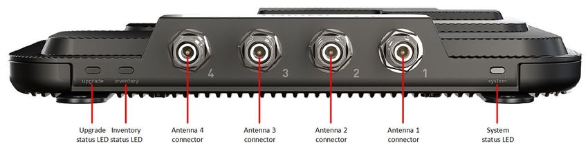
Cloudburst User Manual

Table of contents
1      Introduction .................................................................................................................................................... 3
2      Getting started with Cloudburst ..................................................................................................................... 4
    2.1       Connection through the Ethernet interface ........................................................................................... 4
    2.2       Installation of Cloudburst on the Speedway Revolution Readers (R420/R220/R120) ........................... 6
    2.3       Installation of Cloudburst on the R700 reader ....................................................................................... 9
    2.4       Access Cloudburst Web GUI and first reading ...................................................................................... 12
    2.5       Cloudburst license ................................................................................................................................. 15
3      Network configuration .................................................................................................................................. 16
4      Web GUI description ..................................................................................................................................... 17
5      Operating modes .......................................................................................................................................... 18
6      Interfacing Cloudburst .................................................................................................................................. 19
    6.1       Cloudburst messages and data ............................................................................................................. 19
    6.2       Physical interfaces ................................................................................................................................. 20
    6.3       Protocols and data formats available over the physical interfaces ...................................................... 20
    6.4       JSON data format .................................................................................................................................. 21
    6.5       JSON data format in HTTP POST ........................................................................................................... 21
    6.6       RAW string data format ........................................................................................................................ 22
    6.7       Form encoded RAW string in HTTP POST.............................................................................................. 22
    6.8       FTP file transfer ..................................................................................................................................... 23
7      Communication error .................................................................................................................................... 24
8      Command Line Interface ............................................................................................................................... 25
9      Cloudburst logs ............................................................................................................................................. 26
10         Hardware accessories and combo installation ......................................................................................... 27
    10.1      P-UHF-CBO (Art. N.: 800 3075-967) ...................................................................................................... 27
    10.2      P-UHF-RS232 (Art. N.: 800 3075-969) ................................................................................................... 28
    10.3      P-UHF-SRMIX (Art. N.: 400 5009-358) ................................................................................................... 28
Appendix A - Impinj Speedway Revolution readers ports and LEDs ..................................................................... 29
Appendix B - Impinj Speedway Revolution readers GPIO pinout configuration................................................... 30
Appendix C - Impinj Speedway Revolution readers LEDs status ........................................................................... 32
Appendix D - Impinj R700 reader ports and LEDs ................................................................................................. 33
Appendix E - Impinj R700 reader GPIO pinout configuration ............................................................................... 34
Appendix F - Impinj R700 readers LEDs status ...................................................................................................... 36
Appendix G - Troubleshooting .............................................................................................................................. 37

UM001671                                                             Page 2 / 38                                                          Rev. 7.0 – 10 Nov 2021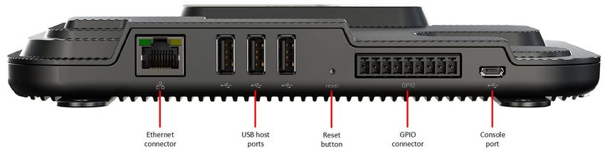
Cloudburst User Manual

1     Introduction
Datamars Cloudburst is a licensed software that runs on the Impinj Speedway® Revolution readers and the
Impinj R700 reader. Cloudburst reduces the overall complexity related to RFID implementation while maximizing
the reader performances in a laundry environment.

Cloudburst enables laundry managers to quickly deploy the RFID system. Web oriented, it simplifies integration
with cloud-based ERP software and allows to easily integrate UHF readers with no need for software
development and deep RFID knowledge.

The reader’s activity and parameters setting are managed through a simple yet powerful Web based GUI.

It comes with pre-configured reading modes that optimize RFID reading performances depending on the reading
station. Cloudburst also provides autonomous start-reading and a set of parameters to control its functionality
that are automatically restored at power up.

Cloudburst supports Ethernet, RS-232 and USB keyboard wedge hardware interfaces. It handles WebSocket,
HTTP POST, RAW TCP/IP socket and FTP protocols and provides flexible and customizable data formats.

The Cloudburst software is also aimed to control the UHF hardware in combination with existing LF and HF
installations, allowing a smooth transition between the three RFID technologies.

UM001671                                     Page 3 / 38                                  Rev. 7.0 – 10 Nov 2021
Cloudburst User Manual
2 Getting started with Cloudburst
2.1 Connection through the Ethernet interface
By default, the Impinj Speedway Revolution and the R700 readers have DHCP client enabled. The IP address
given by the DHCP server or the host name of the reader is needed to reach it via Ethernet interface.
The default hostname of your Speedway Revolution reader is speedwayr-XX-XX-XX where XX-XX-XX shall be
replaced with the last 6 digits of the reader’ MAC address (e.g., speedwayr-11-4b-73).
The default hostname of the R700 reader is impinj-XX-XX-XX where XX-XX-XX shall be replaced with the last 6
digits of the reader’ MAC address (e.g., impinj-13-9c-b0).
Alternatively, if the reader is connected directly to a PC set to automatically obtain an IP address, the reader can
usually be reached at the 169.254.1.1 IP address. Follow the next steps to properly set the configuration of the
Ethernet adapter of your Windows based PC for a direct connection before connecting the reader.
Any other operating system can be configured to properly connect to the reader, please refer to the
documentation of your operating system to know how to change the network settings.
Press the +R keys on the keyboard to show the Run window. Type ncpa.cpl and click “OK” to open the Network
Connections window.
Figure 1 - Open Network Connections
UM001671 Page 4 / 38 Rev. 7.0 – 10 Nov 2021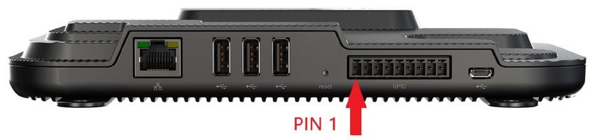
Cloudburst User Manual

Right click on the Local Area Connection icon and then click on Properties.

                                           Figure 2 - Local Area Connection

Select the Internet Protocol Version 4 (TCP/IPv4) item and click on the Properties button.

                                      Figure 3 - Local Area Connection Properties

UM001671                                       Page 5 / 38                                   Rev. 7.0 – 10 Nov 2021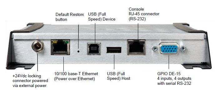
Cloudburst User Manual

Make sure that “Obtain an IP address automatically” is selected in the Internet Protocol Version 4 (TCP/IPv4)
Properties window.

                                Figure 4 - Internet Protocol Version 4 (TCP/IPv4) Properties

Connect the RFID reader directly to the PC with an Ethernet cable and power it up plugging in the power supply
plug.

2.2   Installation of Cloudburst on the Speedway Revolution Readers (R420/R220/R120)

Please note that the following instructions are needed only if Cloudburst is not installed already or in case of a
Cloudburst software update is required. If Cloudburst is already installed on the RFID reader proceed to chapter
2.4.

Download Cloudburst from the Datamars Textile ID website clicking the “Download” button at the following
address https://www.textile-id.com/cloudburst and unzip the downloaded file.

Make sure the UHF reader is ready. It takes about 45 seconds to boot up after power up, it is ready when both
Power LED Status LED are solid green.

Open a web browser (e.g., Google Chrome), type http:// followed by the IP address (e.g., http://169.254.1.1) or
the host name (e.g., http://speedwayr-11-4b-73.local) in the address bar and press Enter.

UM001671                                         Page 6 / 38                                   Rev. 7.0 – 10 Nov 2021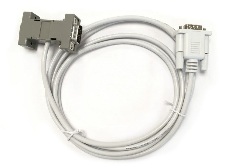
Cloudburst User Manual

Once the connection is established the reader prompts for username and password. Default Username is: root.
Default password is: impinj. Click on the Sign in button.

                       Figure 5 - Impinj Speedway Revolution reader Web management interface login

Cloudburst is tested and validated on Speedway revolution readers running a Software version 7.6.0.240. Please
check it on the “Software Version” in the “Details” section. Running Cloudburst on a reader with a different
software version is still possible although not officially validated, in case of doubts, please contact Datamars
support.

                         Figure 6 - Impinj Speedway Revolution reader Web management interface

UM001671                                        Page 7 / 38                                          Rev. 7.0 – 10 Nov 2021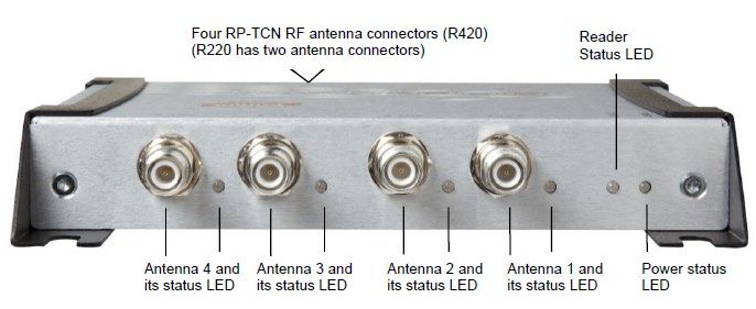
Cloudburst User Manual
Click the “Browse…” button in the “Reader Upgrade” section. Make sure to select the .upg file (e.g.,
Cloudburst_2_4_0_0.upg) in the unzipped folder of the previously downloaded file and click “Open”.
Figure 7 - Select the .upg file
Click on the “Upgrade []” button. The reader uploads Cloudburst and then commits the SW image. The process
is shown in the “Last Operation Status” in the “Reader Upgrade” section, and it lasts about 30 seconds.
When the “Last Operation Status” turns to “Waiting for manual reboot” click on the “Reboot ” button in the
“Reader Reboot” section and then click “OK” in the pop-up window.
Figure 8 - Reboot
UM001671 Page 8 / 38 Rev. 7.0 – 10 Nov 2021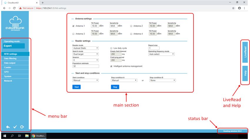
Cloudburst User Manual

The reboot process takes about 1 minute. Wait until the reader is rebooted and the web management interface
is reloaded. If the web page is not automatically refreshed, try refreshing it manually.

When the Web management interface is reloaded you can verify if the installation was successful by checking
the “Application SW Version” shown in the “Details” section of the Web page. The version number must match
the Cloudburst version just installed.

                                      Figure 9 - Verify Cloudburst installed version

If Cloudburst is correctly running the Status LED of the Speedway Revolution reader blinks green.

2.3   Installation of Cloudburst on the R700 reader

Please note that the following instructions are needed only if Cloudburst is not installed already or in case of a
Cloudburst software update is required. If Cloudburst is already installed on the RFID reader proceed to chapterr
2.4.

Download Cloudburst from the Datamars Textile ID website clicking the “Download” button at the following
address https://www.textile-id.com/cloudburst and unzip the downloaded file.

Make sure the UHF reader is ready. It takes about 45 seconds to boot up after power up, it is ready when the
System LED is solid blue.

Open a web browser (e.g., Google Chrome), type http:// followed by the IP address (e.g., http://169.254.1.1) or
the host name (e.g., http://impinj-13-9c-b0.local) in the address bar and press Enter.

UM001671                                        Page 9 / 38                                 Rev. 7.0 – 10 Nov 2021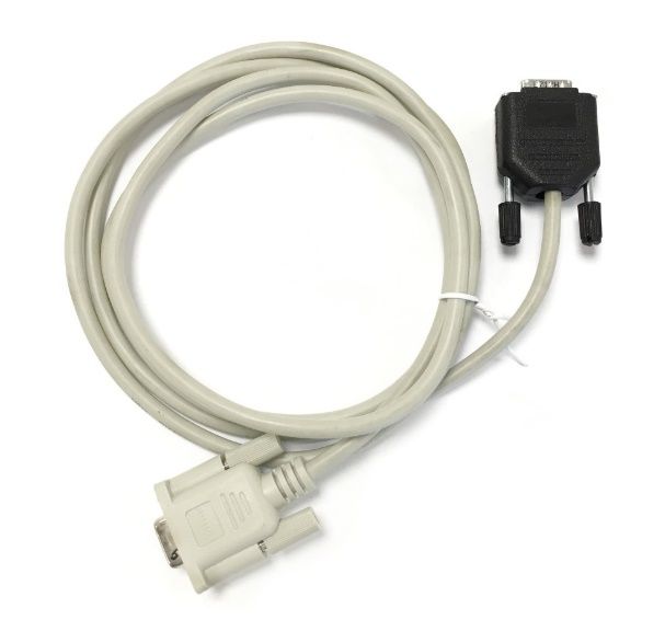
Cloudburst User Manual

Once the connection is established the reader prompts for username and password. Default Username is: root.
Default password is: impinj. Click on the Sign in button.

                             Figure 10 - Impinj R700 reader Web management interface login

Cloudburst is tested and validated on the R700 reader running a Software version 7.6.0.240. Please check it on
the “Software Version” in the “Details” section. Running Cloudburst on a reader with a different software version
is still possible although not officially validated, in case of doubts, please contact Datamars support.

                                Figure 11 - Impinj R700 reader Web management interface

UM001671                                       Page 10 / 38                                  Rev. 7.0 – 10 Nov 2021
Cloudburst User Manual
Click the “Browse…” button in the “Reader Upgrade” section. Make sure to select the .upgx file (e.g.,
Cloudburst_2_4_0_0.upgx) in the unzipped folder of the previously downloaded file and click “Open”.
Figure 12 - Select the .upgx file
Click on the “Upgrade []” button. The reader uploads Cloudburst and then commits the SW image. The process
is shown in the “Last Operation Status” in the “Reader Upgrade” section, and it lasts about 30 seconds.
When the “Last Operation Status” turns to “Waiting for manual reboot” click on the “Reboot ” button in the
“Reader Reboot” section and then click “OK” in the pop-up window.
Figure 13 - Reboot
UM001671 Page 11 / 38 Rev. 7.0 – 10 Nov 2021Cloudburst User Manual
The reboot process takes about 1 minute. Wait until the reader is rebooted and the web management interface
is reloaded. If the web page is not automatically refreshed, try refreshing it manually.
When the Web management interface is reloaded you can verify if the installation was successful by checking
the “Application SW Version” shown in the “Details” section of the Web page. The version number must match
the Cloudburst version just installed.
Figure 14 - Verify Cloudburst installed version
If Cloudburst is correctly running the Inventory LED of the R700 reader blinks blue.
2.4 Access Cloudburst Web GUI and first reading
The Web GUI (Graphical User Interface) allows to configure Cloudburst, manually start, and stop the reading
and check the tag codes read by the reader.
Make sure the UHF reader is ready. It takes about 45 seconds to boot up after power up. The Speedway
Revolution reader is ready when the Power LED is solid green, and the Status LED blinks green while the R700
reader is ready when the System LED is solid blue.
Open a web browser (e.g. Google Chrome), type https:// followed by the IP address (e.g. https://169.254.1.1)
or the host name (e.g. https://speedwayr-11-4b-73.local for the Speedway Revolution readers or https://impinj-
13-9c-b0.local/ for the R700 reader) in the address bar and press Enter.
Depending on the browser privacy settings a security warning may show up. It is totally safe to proceed and
accept the security exception.
UM001671 Page 12 / 38 Rev. 7.0 – 10 Nov 2021Cloudburst User Manual
Figure 15 - Security warning
Click on the advanced button (depending on the browser the security warning may be different from the one
shown here) and then click on the “Proceed to 169.254.1.1”. The security exception can also be permanently
stored to avoid the message showing up every time. Additional information can be found in the browser help
section.
Now the Cloudburst login page is shown. The default password is: password
Figure 16 - Cloudburst login page
Type the password and click the “Login” button. The Cloudburst Web GUI (Graphical User Interface) shows up.
UM001671 Page 13 / 38 Rev. 7.0 – 10 Nov 2021Cloudburst User Manual
Figure 17 - Cloudburst Web GUI
Connect an antenna to the ANT1 connector on the RFID reader and put an RFID tag on the antenna.
Click on the “LiveRead” button on the right side of the page and then click on the “Start” button. The LiveRead
allows to immediately see the EPC (Electronic Product Code) of the RFID tags read.
Figure 18 - LiveRead test
UM001671 Page 14 / 38 Rev. 7.0 – 10 Nov 2021Cloudburst User Manual
2.5 Cloudburst license
Without a valid license file provided by Datamars, Cloudburst allows to read approximately 1000 tags for
evaluation purpose. After 1000 tags read, Cloudburst stops working and a valid license file is required to unlock
all the Cloudburst functionalities.
The license file can be loaded in the “System” tab of the Web GUI. The license file name is the serial number of
the reader the license has been generated for (e.g.: 37015110056.clf).
Depending on the options included in the purchased license, Cloudburst unlocks additional features. The list of
enabled options is shown on the Web GUI.
Figure 19 – System tab, license loaded
UM001671 Page 15 / 38 Rev. 7.0 – 10 Nov 2021Cloudburst User Manual
3 Network configuration
The network configuration of the reader can be changed in the “Network” tab of the Cloudburst Web GUI.
Any changes to the “Network” tab will automatically reboot the reader after the new settings are applied. When
the reboot process completes the Cloudburst Web GUI shall be manually reloaded with the new IP address or
hostname.
In case of static address mode, remember to double check that all the settings are correct before applying the
new changes. In case of a mistake, the reader could potentially be not reachable anymore through the ethernet
interface. If this happens, please refer to Appendix D.
None of the network settings are saved in the Cloudburst configuration file. The network configuration is stored
and managed by the operating system running on the reader.
Figure 20 – Network configuration
UM001671 Page 16 / 38 Rev. 7.0 – 10 Nov 2021Cloudburst User Manual
4 Web GUI description
The Cloudburst Web GUI has four sections, the menu bar on the left, the main section in the middle, the LiveRead
and Help tabs on the right and the status bar in the bottom left corner.
Figure 21 - Cloudburst Web GUI sections
The menu bar allows to select the operating mode, navigate through the different tabs and at the bottom there
are three buttons to discard changes, apply changes and log out.
The main section shows the settings and the parameters available depending on the selected tab.
The LiveRead and Help tabs on the right side of the page allow to open the LiveRead tab and see the online Help.
The online Help provides detailed description of every parameter and functionality.
The status bar provides information on the current status of the reading window.
UM001671 Page 17 / 38 Rev. 7.0 – 10 Nov 2021Cloudburst User Manual 5 Operating modes The Operating modes are Datamars made pre-sets to allow easier and quicker RFID setup without requiring deep RFID knowledge. Depending on the license and the reader Cloudburst is installed on, some operating modes are not available. The full list of available modes is: - Disabled - Expert - S-UHF-LITECAB - S-UHF-CAB - S-UHF-PORTAL - S-UHF-PORTAL+ - TableTop - S-UHF-ARCH - RoF - S-UHF-TUNNEL The Disabled operating mode allows to establish an LLRP connection to the RFID reader with an external application without having to remove Cloudburst. The disabled operating mode is not permanently saved, the previous Cloudburst configuration will be restored after reboot. If the LLRP connection is not available (because the external application is still connected) Cloudburst will refuse to switch to back to another operating mode. The Expert operating mode allows to set every parameter of the reader. It is intended for installations where a standard setup is not applicable. The Datamars reading systems work properly only if the appropriate Operating mode is selected. Please visit Datamars Textile ID website for more information about our reading systems: https://www.textile- id.com/textile-id-rfid-products UM001671 Page 18 / 38 Rev. 7.0 – 10 Nov 2021
Cloudburst User Manual

6     Interfacing Cloudburst
6.1   Cloudburst messages and data

Cloudburst data output is flexible and customizable. The Web GUI allows to specify which information shall be
included in the output simply dragging and dropping tokens in the desired order.

                                         Figure 22 - Tag data output format

Tag data include:

-     EPC (HEX format, supports any EPC length e.g. 96 or 128 bits, customizable length filter to cut the EPC)
-     Timestamp (Date and time or UNIX format)
-     Antenna port
-     RSSI
-     Customizable prefix and suffix (in standard ASCII characters or HEX format for special characters)

Cloudburst also allows to send some status messages to indicate the status of the system and ongoing
operations. They can be enabled if needed.

The following messages are currently available:

-      sent every time a reading window begins. It is guaranteed that all the tag codes belonging the
      just started reading window are sent after the  message.
-      sent every time a reading window ends. It is guaranteed that all the tag codes belonging to the
      just ended reading window are sent before the  message.
-      sent when the reading has been stopped due to a failure or a misuse of the reading system.
      EPCs of the current acquisition should be discarded.
-      sent when a cart enters the S-UHF-PORTAL+ on side A.
-      sent when a cart enters the S-UHF-PORTAL+ on side B.
-      periodically sent to allow the upper SW layers to check if the RFID system and the physical
      link is alive.
-      sent every time the status of a GPI changes. X represents the logic level of the respective GPI
      and it can be 0 or 1, e.g.

Every message is followed by a new line character(s).

Please note that other messages can be added in the future. The upper SW layer shall be able to handle
“unexpected” messages.

UM001671                                     Page 19 / 38                                  Rev. 7.0 – 10 Nov 2021
Cloudburst User Manual
6.2 Physical interfaces
Cloudburst manages the following physical interfaces of the RFID reader:
- Ethernet
- RS-232 serial port
- USB keyboard wedge (HID)
6.3 Protocols and data formats available over the physical interfaces
Over the Ethernet interface the following protocols and data formats are available:
- WebSocket (client and server)
- JSON
- RAW string
- HTTP POST
- JSON
- Form encoded RAW string
- RAW TCP/IP socket (server)
- RAW string
- FTP (client)
- CSV file containing RAW string
The WebSocket server uses Ping/Pong frames. Cloudburst periodically send a Ping frame every 60 seconds. The
client shall respond with a Pong frame. After five consecutive missing Pong frames, Cloudburst closes the
WebSocket connection.
When using the HTTP POST data output and the transfer condition is set to “Minimum POST period”, it is
important to remember that the HTTP POST data transmission cannot always be immediate. Only the first POST
message is sent as soon as (at least) one message is available. Consecutive messages are periodically sent on a
configurable time base if EPCs come faster than the minimum POST period.
Independently from the selected HTTP POST transfer condition, Cloudburst can buffer up to 5000 EPCs between
two consecutive messages. If the buffer fills up a data loss will occur. It is user responsibility to prevent this.
If an HTTP POST fails, Cloudburst re-tries to send the message up to five times with one second delay between
each attempt. EPCs in the buffer are discarded if the HTTP POST doesn’t succeed (after the fifth attempt),
resulting in a data loss.
Up to five simultaneous RAW TCP/IP connections can be established. When the limit is reached, Cloudburst will
not allow new connections to be established, automatically closing them.
Then using FTP, cloudburst can buffer up to 5000 EPCs between two consecutive file transfers. If the buffer fills
up a data loss will occur. It is user responsibility to prevent this. If a file transfer fails, Cloudburst re-tries to send
the file up to five times with one second delay between each attempt. EPCs in the buffer are discarded if the file
transfer doesn’t succeed (after the fifth attempt), resulting in a data loss.
Over the RS-232 serial interface the RAW string is the only format available.
UM001671 Page 20 / 38 Rev. 7.0 – 10 Nov 2021Cloudburst User Manual
Over the USB keyboard wedge interface, the RAW string is the only format available. Some special characters
may not be supported by the keyboard wedge, this also depends on the keyboard layout. A “_” character is
typed if the corresponding character is not supported. The New line character(s) does not apply to keyboard
wedge, at the end of every line the virtual keyboard simulates an “Enter” key.
6.4 JSON data format
The JSON format is the following:
{
antennaPort:integer
epc:string
timestamp:string
peakRssi:integer
statusMessage:string
}
Please note that the content of the structure is dynamic, it depends on the configuration in the tag data output
format.
Here are two examples of how JSON messages look like:
{
antennaPort:1
epc:“300ED89F3350008CCCD5387D”
timestamp:“27.11.2018 09:15:52”
peakRssi:-32
}
{
statusMessage:“”
}
6.5 JSON data format in HTTP POST
The following is an example of a JSON message in the HTTP POST:
{
reader_name:"test“
mac_address:“00:16:25:11:4B:73“
tag_reads[
{
antennaPort:1
epc:“300ED89F3350008CCCD5387D”
timestamp:“27.11.2018 09:15:52”
peakRssi:-32
}
{
antennaPort:2
epc:“300ED89F3350008CCCD47A20”
timestamp:“27.11.2018 09:15:52”
peakRssi:-41
}]
}
UM001671 Page 21 / 38 Rev. 7.0 – 10 Nov 2021Cloudburst User Manual
6.6 RAW string data format
In the RAW string format, the information is sent out as a regular string terminated by a configurable new line
character(s).
The string content and format as well as the separator and the new line character(s) are widely customizable
through Cloudburst Web GUI.
Strings are sent out over the selected output interface(s) one after the other when tags are read.
The following picture show some RAW strings collected with a terminal emulator.
Figure 23 - RAW string data format example
6.7 Form encoded RAW string in HTTP POST
The form encoded RAW string is available only for HTTP POST. RAW strings are encoded in the form of the POST
message.
The following is an example of how an HTTP POST message looks like:
Details
-------
ID: 1620001
Timestamp: 2018-11-13 17:27:18.766579 +0000 UTC
Method: POST
IP: 46.140.130.59
Headers
-------
Accept: */*
Content-Length: 490
Content-Type: application/x-www-form-urlencoded
Host: ptsv2.com
X-Cloud-Trace-Context: b5801757a8a3dfbffcec2133c48a6924/12616760292335380827
X-Google-Apps-Metadata: domain=gmail.com,host=ptsv2.com
Parameters
----------
reader_name="test“
mac_address=“00:16:25:11:4B:73“
field_delim=,
field_names=epc,timestamp,antenna_port,peak_rssi
field_values:300ED89F3350005001116B74,27.11.2018 09:15:03,1,-15
UM001671 Page 22 / 38 Rev. 7.0 – 10 Nov 2021Cloudburst User Manual 300ED89F3350004001116BFB,27.11.2018 09:15:03,1,-20 300ED89F3350008CCCD53759,27.11.2018 09:15:03,1,-38 300ED89F3350008CCCD5387D,27.11.2018 09:15:03,1,-32 300ED89F3350004001116B3C,27.11.2018 09:15:03,1,-24 300ED89F3350004001116B96,27.11.2018 09:15:03,1,-48 Body ---- No body Files ----- No files Multipart Values ---------------- No Multipart Values 6.8 FTP file transfer Cloudburst allows to save on an FTP server a .csv file containing the EPCs and status messages. The supported FTP protocols are: FTP, FTPS and SFTP. There are three conditions that trigger the file transfer: - End of reading window - Timeout - Number of tag observations The file name header is customizable, and it is followed by the timestamp and the .csv extension e.g.: filename_20190809153423.csv When FTP is enabled, keep alive can be used to periodically verify that a file can be written on the server. Every time the keep alive is triggered a “.keepalive” file is saved on the FTP server. The FTP output protocol is optional, it is not included in the basic license. UM001671 Page 23 / 38 Rev. 7.0 – 10 Nov 2021
Cloudburst User Manual

7     Communication error
When HTTP POST or FTP output interfaces are enabled Cloudburst can trigger a communication error.

The communication error is shown in the status bar of the Web GUI. The communication error state can also be
linked to a GPO allowing to turn on a physical alert (e.g., a buzzer or an LED) whenever a communication error
occurs.

The HTTP POST set the communication error when a POST does not end up successfully.

The FTP set the communication error only when the keep alive is enabled (keep alive period different from 0).
If a keepalive message cannot be successfully saved on the FTP server the communication error is set.

The communication error is cleared as soon as the POST or FTP communication is restored or when they are
disabled in the configuration.

UM001671                                    Page 24 / 38                                 Rev. 7.0 – 10 Nov 2021
Cloudburst User Manual

8     Command Line Interface
Cloudburst offers a Command Line Interface. It is available over the RAW TCP/IP socket, WebSocket (server) and
RS-232 serial.

Commands may be implemented in the upper SW layer to control the reader operation. For example, start
reading when the user clicks a button on the SW’s GUI.

Commands must be followed by the enter key to be accepted.

Depending on the selected Operating mode, some commands may not be available, or their behaviour might be
different.

The currently available commands are listed in the following table.

               command                  syntax              n parameter            x parameter

        start reading              *d                -                      -

        stop reading               *i                -                      -

        set a GPO                  *go[n][x]         GPO number             active level (0 or 1)

A terminal emulator (e.g. Putty) can be used to manually send commands to the Cloudburst’ Command Line
Interface.

UM001671                                         Page 25 / 38                             Rev. 7.0 – 10 Nov 2021
Cloudburst User Manual
9 Cloudburst logs
Cloudburst allows to log useful information to help checking the status of the system and make troubleshooting
easier in case of problems.
Logs are saved on the reader’s memory, additionally, the address of a syslog server can also be specified. Syslog
is a standard and widely used protocol to manage logs.
Local logs can be downloaded directly from the Cloudburst Web GUI.
Figure 24 – System tab, syslog settings
UM001671 Page 26 / 38 Rev. 7.0 – 10 Nov 2021Cloudburst User Manual
10 Hardware accessories and combo installation
One of the main features of Cloudburst is the Combo mode. It allows to connect together LF, HF and UHF readers
through the serial interface to make the coexistence of different RFID technologies easy and to simplify the
migration between different technologies.
Special cables are needed to connect the LF and HF readers to the UHF reader.
When in combo mode the Impinj Speedway Revolution reader can act as a master, collecting the data from the
LF or HF reader connected to it and sending the tag ID codes of both systems on the selected communication
interfaces. An example is an LF and UHF combo installation, the tagIDs and the EPCs are collected by Cloudburst
and sent over the Ethernet interface.
Several settings and combo modes are available in Cloudburst. Refer the online Help in the Web GUI for more
information.
10.1 P-UHF-CBO (Art. N.: 800 3075-967)
The P-UHF-CBO cable allows to connect an LF or HF reader to the UHF reader and take advantage of the combo
mode available in Cloudburst.
With this special cable LF/HF data is sent to the UHF reader and it still allows, depending on Cloudburst settings,
to combo codes to the PC via serial port if needed. It is important to note that when this cable is used, the
Cloudburst Command Line Interface over serial port is not accessible anymore.
Connect the male DB-9 connector to the serial port of the LF or HF reader. Connect the HDB-15 connector to the
GPIO port of the UHF reader. The female DB-9 connector allows to connect the PC.
Figure 25 - P-UHF-CBO cable
When using the system in combo mode the baud rate of the UHF reader shall match the one of the LF or HF
reader.
Using this cable and the combo mode continuous reading is allowed without any risk of data collision.
UM001671 Page 27 / 38 Rev. 7.0 – 10 Nov 2021Cloudburst User Manual
10.2 P-UHF-RS232 (Art. N.: 800 3075-969)
To connect the UHF RFID reader via RS-232 interface, the P-UHF-RS232 is needed. Connect the HDB-15
connector to the GPIO port of the UHF reader and the DB-9 connector to the PC.
Figure 26 - P-UHF-RS232 cable
10.3 P-UHF-SRMIX (Art. N.: 400 5009-358)
The P-UHF-SRMIX cable allows to connect an LF or HF reader and the UHF reader to a PC via RS-232 interface.
With this special cable LF/HF data and UHF data is mixed and sent to the PC directly. It is important to note that
it is not possible to read at the same time LF/HF and UHF codes, only single readings are allowed. A collision
would make impossible to correctly receive the tag codes.
The Cloudburst combo mode does not work with this cable.
Connect the male DB-9 connector to the serial port of the LF or HF reader. Connect the HDB-15 connector to the
GPIO port of the UHF reader. The female DB-9 connector allows to connect the PC.
Figure 27 - P-UHF-SRMIX cable
When using this cable, the baud rate of the UHF reader shall match the one of the LF or HF reader.
UM001671 Page 28 / 38 Rev. 7.0 – 10 Nov 2021Cloudburst User Manual
Appendix A - Impinj Speedway Revolution readers ports and LEDs
The Impinj Speedway Revolution reader is equipped with standard communication interfaces like Ethernet, USB
and RS-232.
It offers four General Purpose Inputs (GPI) and four General Purpose Outputs (GPO) which allow to integrate its
operation in automated systems or connect sensors and actuators to it.
Four, two or one antenna ports are available depending on the model of the reader (SR420 / SR220 / SR120).
See “Appendix B - Impinj Speedway Revolution readers GPIO pinout configuration” for functional and electrical
specifications and details for each pin of the GPIO DE-15 connector.
Status LEDs are also available, see Appendix C for details about LEDs status meaning.
Figure 1.A - Impinj Speedway Revolution reader interfaces
Figure 2.A - Impinj Speedway Revolution reader antenna ports and status LEDs
UM001671 Page 29 / 38 Rev. 7.0 – 10 Nov 2021Cloudburst User Manual
Appendix B - Impinj Speedway Revolution readers GPIO pinout configuration
Speedway R420 / R220 / R120 include a multipurpose I/O port that contains an RS-232 serial port, four opto-
isolated inputs, four opto-isolated outputs and a +5V supply. They can be accessed through a DE15 connector
mounted on the side of the Reader.
The reader considers an input of 0-0.8V as a logic 0, and an input of 3-30V as a logic 1 on the GPIs. The four opto-
isolated inputs allowed voltage range is 0-30V DC.
The reader also provides four opto-isolated DC outputs. An external provided supply must be connected
between V+ and V-. The maximum allowed voltage is 30V DC.
When the user configures a GPO to logic 0, an isolated FET switch within the reader effectively shorts that output
to V- with a current sink capability of up to 100mA. When the user configures a GPO to logic 1, the selected
output is pulled to V+ through a 10K resistor. If GPIO isolation is not required, the reader provides a +5V supply
and a ground pin on the DE-15 that can be connected to V+ and V-.
Figure 1.B - GPIO connector pin numbering
Pin I/O Name I/O Function
1 +5V Supply Reader supplied (not isolated) power source
2 RS-232 RX For auxiliary serial port functions
3 RS-232 TX For auxiliary serial port functions
4 Processor Reset Reserved for future use. Do not connect this pin to any signal
5 V+ Power source for isolated outputs
6 V- Return for isolated inputs and outputs
7 Ground Reader (not isolated) return
8 User OUT 1 Isolated output 1 (active pull down to V-)
9 User OUT 2 Isolated output 2 (active pull down to V-)
10 User OUT 3 Isolated output 3 (active pull down to V-)
11 User OUT 4 Isolated output 4 (active pull down to V-)
12 User IN 1 Isolated input 1
13 User IN 2 Isolated input 2
14 User IN 3 Isolated input 3
15 User IN 4 Isolated input 4
Table 1.B – DB15 connector pinout
UM001671 Page 30 / 38 Rev. 7.0 – 10 Nov 2021Cloudburst User Manual
Pin Parameter Description Min Max Unit Conditions
+5V Supply IO Output current 200 mA
User IN 1-4 VIH HIGH level input voltage 3 30 V
User IN 1-4 VIL LOW level input voltage 0 0.8 V
User IN 1-4 VLI Input current 5 mA 24V input
User IN 1-4 VI Input voltage range 0 30 V No damage
User Out 1-4 VOH Output high voltage V+* V 10kΩ pull-up
User Out 1-4 VOL Output low voltage (V-)+0.5 V 100mA load
V+* IO Input voltage range 0 30 V
Table 2.B – GPIO interface, electrical specification
* User-supplied voltage.
UM001671 Page 31 / 38 Rev. 7.0 – 10 Nov 2021Cloudburst User Manual
Appendix C - Impinj Speedway Revolution readers LEDs status
The following table describes the LEDs behavior for various reader states:
Reader operation LED Expected behaviour
Power applied, Power Solid red
Attempting to start boot code Status Off
Start-up (power on) Bootloader calling firmware Power Solid green
normal completion image Status Off
Bootloader completed Power Solid green
successfully; Reader is ready Status Solid green
Default restore button Power Turns off
pressed Status Off
Blinks once (red), indicates a
Default restore button
Startup (reset) Power configuration default restore will
pressed for 3 seconds
normal completion occur
Blinks twice (red), indicates a factory
Default restore button default restore will occur. Resets
Power
pressed for 10 seconds reader configuration and removes CAP
(if present)
Hardware problems detected, Power Continuous blinking red
Startup (failure)
unable to boot Status Off
Upgrading the firmware
Upgrade activity Status Alternates between red and green
during boot process
Detects no activity on antenna
Antenna Off
Detection of antenna port
activity Detects antenna transmission
Antenna Solid green
activity on antenna port
Performing an inventory Blinks orange, blinks faster as tag
Inventory activity Status
operation volume increases
LLRP activity Active LLRP connection Status Double blink pattern (green)
LLRP activity Disconnect operation Status Single blink pattern (green)
Table 1.C – LEDs status description
UM001671 Page 32 / 38 Rev. 7.0 – 10 Nov 2021Cloudburst User Manual
Appendix D - Impinj R700 reader ports and LEDs
The Impinj R700 reader is equipped with standard communication interfaces like Ethernet and USB.
It offers two General Purpose Inputs (GPI) and three General Purpose Outputs (GPO) which allow to integrate
its operation in automated systems or connect sensors and actuators to it.
Four antenna ports are available.
See Appendix E “Impinj R700 reader GPIO pinout configuration”, for functional and electrical specifications and
details for each pin of the Phoenix Contact MC 1,5/ 9-G-3,81 modular connector.
Status LEDs are also available, see “Appendix F - Impinj R700 readers LEDs status” for details about LEDs status
meaning.
Figure 1.D – Impinj R700 reader interfaces
Figure 2.D – Impinj R700 reader antenna ports and status LEDs
UM001671 Page 33 / 38 Rev. 7.0 – 10 Nov 2021Cloudburst User Manual
Appendix E - Impinj R700 reader GPIO pinout configuration
The Impinj R700 reader includes a multipurpose I/O port that provides two general-purpose opto-isolated
inputs, three opto-isolated outputs, and a +5V supply. You access these features through a 9-pin connector
mounted on the side of the reader.
The reader considers an input of 0-0.8V as a logic 0, and an input of 3-30V as a logic 1 on the GPIs. The four opto-
isolated inputs allowed voltage range is 0-30V DC.
The reader also provides three opto-isolated DC outputs. An external provided supply must be connected
between V+ and V-. The maximum allowed voltage is 30V DC.
When the user configures a GPO to logic 0, an isolated FET switch within the reader effectively shorts that output
to V- with a current sink capability of up to 1500mA. When the user configures a GPO to logic 1, the selected
output is pulled to V+ through a 10K resistor. If GPIO isolation is not required, the reader provides a +5V supply
and a ground pin on the connector that can be connected to V+ and V-. The +5V pin is current limited to 500mA,
max.
Figure 1.E GPIO connector pin numbering reference
Pin I/O Name I/O Function
1 +5V Supply Reader supplied (not isolated) power source, 500 mA max
2 Chassis ground Reader (not isolated) return
3 User IN 1 Isolated input 1
4 User IN 2 Isolated input 2
5 User OUT 1 Isolated output 1 (active pull down to V-)
6 User OUT 2 Isolated output 2 (active pull down to V-)
7 User OUT 3 Isolated output 3 (active pull down to V-)
8 V- Return for isolated inputs and outputs
9 V+ Power source for isolated outputs
Table 1.E GPIO connector pinout
UM001671 Page 34 / 38 Rev. 7.0 – 10 Nov 2021Cloudburst User Manual
Pin Parameter Description Min Max Unit Conditions
+5V Supply IO Output current 500 mA
User IN 1-2 VIH HIGH level input voltage 3 30 V
User IN 1-2 VIL LOW level input voltage 0 0.8 V
User IN 1-2 VLI Input current 5 mA 24V input
User IN 1-2 VI Input voltage range 0 30 V No damage
User Out 1-3 VOH Output high voltage V+* V 10kΩ pull-up
User Out 1-3 VOL Output low voltage (V-)+0.5 V 100mA load
V+* IO Input voltage range 0 30 V
Table 2.E GPIO interface, electrical specification
* User-supplied voltage.
UM001671 Page 35 / 38 Rev. 7.0 – 10 Nov 2021Cloudburst User Manual
Appendix F - Impinj R700 readers LEDs status
The following table describes the LEDs behaviour for various reader states:
Upgrade LED patterns:
LED state Reader state
OFF FW upgrade inactive or FW upgrade fail
Blinking blue FW upgrade in progress
Solid blue (until next reboot) FW upgrade successful
Table 1.F – Upgrade LED patterns
Inventory LED patterns:
LED state Reader state
OFF RO spec disabled (IDLE)
Blinking blue RO spec inactive (ARMED)
Solid blue RO spec active (RUNNING)
Table 2.F – Inventory LED patterns
System LED patterns:
LED state Reader state
OFF Power not applied
Blinking yellow Factory default restore detected
Solid yellow Power applied, booting
Solid blue Boot successful
Blinking red Boot error, USB upgrade error, other error
Table 3.F – System LED patterns
Inventory LED patterns:
LED state Reader state
OFF Antenna inactive
Solid blue Antenna active
Table 4.F – Inventory LED patterns
UM001671 Page 36 / 38 Rev. 7.0 – 10 Nov 2021Cloudburst User Manual
Appendix G - Troubleshooting
If any problem arises while using Cloudburst, the following table should help to correct the issue. If the problem
persists, contact Datamars support at support-tid@datamars.com or call the landline support at: +41 91 935 73
80.
Symptom Cause and/or corrective actions
• Is the reading running, check the status bar in the Web GUI?
• Open the LiveRead tab and check if EPCs are shown.
There are UHF transponder on the • Is the antenna connected to the right antenna port? (by
antenna but no EPCs are sent over the default, the antenna 1 is enabled and set to 16 dBm
interface transmitting power)
• Check if the Antenna 1 LED nearby the antenna connector is
light up in green/blue.
• If the reader is not connected to the LAN through the
Ethernet cable, Cloudburst could take about 2 minutes
Cloudburst is not running right after
before start-up. This behaviour can be avoided assigning a
power up
fixed IP to the Ethernet interface of the reader even if it is
not used or connecting it to the LAN.
• Restore the Default Configuration of the reader. The
procedure is explained in the next page.
• The network configuration can be change via console port. A
The network configuration is unknown, CISCO console cable is required for the Speedway Revolution
or the reader is not reachable through readers and a micro USB cable is required for the R700
Ethernet interface reader. For more information about the IP settings through
the console port see readers documentation available on the
Impinj website: https://support.impinj.com/hc/en-
us/categories/200156268-Readers
Table 1.G - Troubleshooting symptoms and actions
Restoring to the Default Configuration
If you are experiencing a problem with the reader and are having difficulty pinpointing the cause, it is useful to
return the reader to a known state. We recommend resetting to the default configuration. Then try the reader
again.
Please carefully read the whole paragraph before proceeding with this procedure. Important: Configuration
Default Restore returns the reader configuration to its default state. It leaves any custom applications, such as
Cloudburst, installed in the CAP (Custom Application Partition) intact. To restore the reader to its default state
and remove any CAP contents, use Factory Default Restore.
There are two ways to return a Speedway Revolution or R700 reader to its defaults:
- Issue an RShell command.
- Push the Default Restore button on the device.
UM001671 Page 37 / 38 Rev. 7.0 – 10 Nov 2021Cloudburst User Manual
To use RShell to return the Reader to its default configuration and leave CAP intact
1. At the RShell prompt, enter the following command: config image default
When the command completes successfully, the Reader automatically reboots and returns to the login
prompt.
2. Log in to the reader. The reader is now running with the default configuration. CAP applications are
intact.
To use the Default Restore button on the Reader to restore to its default configuration
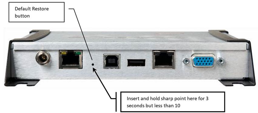
1. Use an object with a sharp tip, such as a probe or paper clip to press and hold the default restore button
on the back of the reader while applying power to the reader.
2. Continue holding the default restore button for 3 seconds after the power LED light turns off, but not
longer than 10 seconds.
3. Release the default restore button when the LED blinks red once. The reader will boot up normally with
the default configuration.
Figure 1.G - Speedway revolution reader default restore button timings
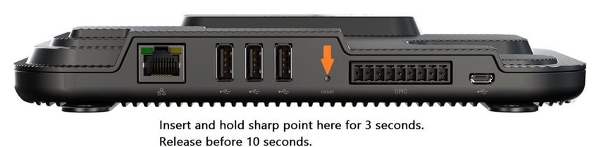
Figure 2.G - R700 reader default restore button timings
Warning: pressing the default restore button for 10 seconds or more will cause a factory default restore to
occur. The factory default restore removes the reader’s custom application partition (CAP) if one exists. The
reader returns to the original, factory shipped state. It is important to avoid accidentally removing the CAP,
although there may be situations where CAP removal is necessary.
UM001671 Page 38 / 38 Rev. 7.0 – 10 Nov 2021You can also read