VEHICLE SYSTEM INTERFACE MODULE (VSIM) - Ram Trucks
←
→
Page content transcription
If your browser does not render page correctly, please read the page content below
VEHICLE SYSTEM INTERFACE MODULE (VSIM)

     The Vehicle System Interface Module (VSIM) is specifically designed to make it easy to upfit RAM trucks. The VSIM has
     many hard wired inputs and outputs (through the VSIM jumper harnesses) . It also has J1939 communication bus output
     signals as well as input commands starting in 2019. The VSIM allows the upfitter turn on certain features or functions
     with hardwired or J1939 commands. It also a outputs signals and relay driver control circuits based on the vehicle
     information.
     The VSIM is required for PTO functionality but the PTO will not work unless there is PTO Prep on the truck. For 2019 the
     VSIM is standard on the Chassis Cabs. It is a stand alone option or part of a package on 2500 and 3500 pick ups, including
     box off pick ups. The VSIM cannot be added to the vehicle after assembly. It is not a dealer or after market installable
     feature and must be ordered from the factory as standalone option or part of a package or option on pick up trucks.

     All VSIM Inputs, Outputs and J1939 signals only function when the vehicle is awake and the vehicle communication bus
     is active except for Door Lock and Unlock inputs. The VSIM will not function with the key in the off position and the bus
     asleep except for those inputs. Outputs such as gear position, including Park Position will turn off when the VSIM goes
     to sleep (vehicle communication bus goes to sleep). An example would be turning the ignition off with no other feature
     keeping the vehicle awake.

      This document shows the following information:
      • Location of the VSIM ,which is new for 2019
      • Location of the VSIM Jumper Connectors (use caution to make sure they are plugged into the correct location)
      • VSIM Hardwired Input and Output information
      • VSIM J1939 SAE and Ram Specific Input Commands and Output Messages

                                                        VSIM General Information
                                                                                                                        All Rights Reserved
3/1/2019
                                                                                                                            1 of 16
FCA US LLC - Body Builder Instruction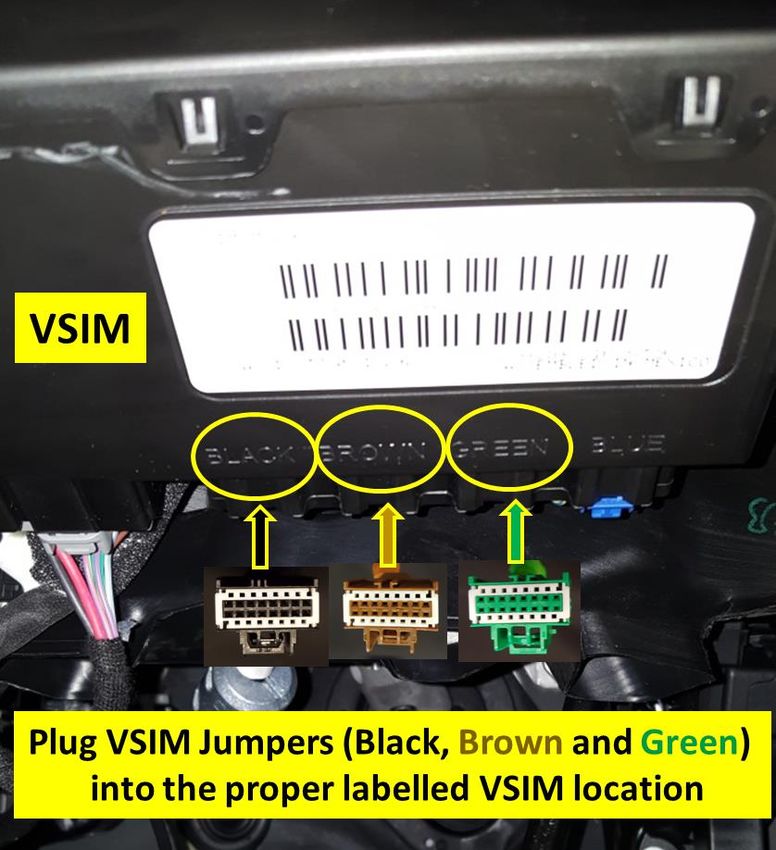
VSIM LOCATION

     The VSIM location changed for 2019. The VSIM is
     now located underneath the Steering Column behind
     the steering column trim cover (knee blocker).

                                                   VSIM Location
                                                                   All Rights Reserved
3/1/2019
FCA US LLC - Body Builder Instruction                                    2 of 16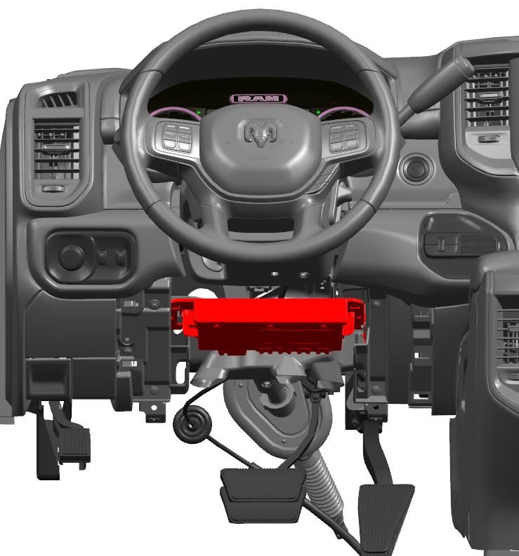
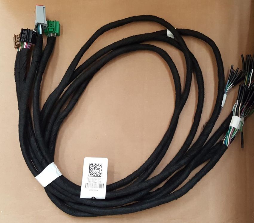
VSIM Jumper Harnesses

    The VSIM Jumper Harnesses with the
   Brown, Black, Green and Gray
   connectors and blunt cut wires on the
   opposite end. The Brown, Black and
   Green Connectors plug directly into the
   VSIM connectors. They must be
   plugged into the properly labeled
   connector. The Gray Connector plugs
   into the inline mating connector that is
   located above the accelerator pedal
   bracket.

   * It is recommended that when routing
   the harness additional harness
   protection such as convolute be used to
   protect the harness from abrasion.
                                              VSIM Jumper Harness
                                                                    All Rights Reserved
3/1/2019
FCA US LLC - Body Builder Instruction                                     3 of 16
VSIM Direct Connect Jumper Harnesses

                                                                                         All Rights Reserved

 3/1/2019                                        VSIM Direct Connect Jumper Connectors
FCA US LLC - Body Builder Instruction                                                          4 of 16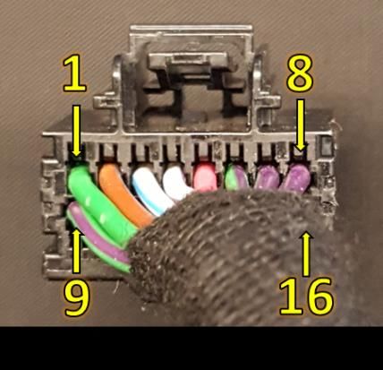
VSIM Gray 24 Cavity In-line Connector Jumper Harness

     The VSIM Gray 24 Cavity In-line mating connector
     is locate above the accelerator pedal bracket.

                                            VSIM Gray Jumper 24 Cavity In-line Connector Locations
                                                                                                     All Rights Reserved
3/1/2019
FCA US LLC - Body Builder Instruction                                                                      5 of 16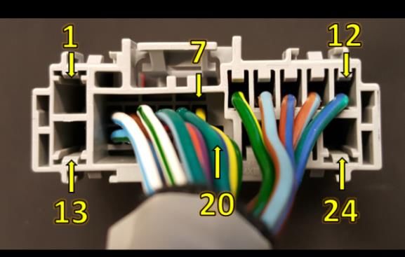
VSIM 16 - CAVITY BLACK CONNECTOR 2019

                                                                   Max

                                               Circuit
                                                         Wire
PIN           Upfitter VSIM Signal                               Current    Type of Signal                                                                      Function
                                                         Color
                                                                 (Amps)

1     Howler Siren disable                     W505       GN                  HSD Output        Open circuit when vehicle speed is below 25 MPH, battery positive voltage (+12V) when vehicle speed is 25 MPH or above.

2     Horn activation                          W513      BN/GY     0.5        HSD Output        Open circuit when horn not pressed (not energized), battery positive voltage (+12V) when pressed (energized).

3     Left Turn Signal                         W682      WH/BU     0.5        HSD Output        Open circuit when turn signals are off High Side (+12 V) turns on and off with left turn signal

4     High Beam                                W684      WH/VT     0.5        HSD Output        Open circuit when high beams off. High Side (+12 V) turns on when high beams are on.

5     Power feed "Off"                         W735       PK       0.5        HSD Output        Open circuit when key position is in "Accessory/Run/Start", battery positive (+12) when key is in off position.

                                                                                                Open circuit when the drivers seat belt is latched, battery positive voltage (+12V) when the drivers seat belt is not latched (key must be
6     Driver Seat Belt not latched             W710      GN/VT     0.5        HSD Output
                                                                                                in "run" position.

                                                                           Digital Signal LSD   Oil Pressure Signal: Pulse Width Modulated (PWM) between open circuit and ground, 100 Hz, linear with 0 % PWM = 0 PSI, and 100 %
7     Oil Pressure Warning Signal PWM          W707      VT/GY     0.1
                                                                           PWM Output           PWM = 147 PSI.

                                                                           Digital Signal LSD   Battery Voltage Signal: Pulse Width Modulated (PWM) between open circuit and ground, 100 Hz, linear with 0 % PWM = 5V, and 100 %
8     Voltage Gauge      PWM                   W733       VT       0.5
                                                                           PWM Output           PWM = 18V.

                                                                                                Open circuit when front airbags have not deployed during current key on cycle, battery positive (+12V) upon front airbag deployment
9     Airbag Deployed                          W685      GN/VT     0.5        HSD Output
                                                                                                during current key on cycle.

                                                                                                Open circuit when Vehicle Theft Alarm (VTA) is not alarming. When VTA is armed and alarming (horn sounding and lamps blinking),
10    Vehicle Theft Alarm (active- alarming)   W515      VT/BU     0.5        HSD Output
                                                                                                there is a battery positive voltage (+12V).

                                                                                                Open circuit when Service Brake Pedal is not active, battery positive voltage (+12V) when the Service Brake Pedal is active (key may be
11    Service Brake Pedal depressed            W726      DG/OG    0.25        HSD Output
                                                                                                in any position).

12    Power feed "Accessory"                   W734      PK/GY     0.5        HSD Output        Open circuit when key position is in "Off/Run/Start", battery positive (+12) when key is in "Accessory" position.

13    Power feed "Run/Start"                   W736      PK/YE     0.5        HSD Output        Open circuit when key position is in "Off/Accessory", battery positive (+12) when key is in "Run or Start" position.

                                                                           Digital Signal LSD   Fuel Level Signal: Pulse Width Modulated (PWM) between open circuit and ground, 100 Hz, linear with 0 % PWM = empty tank, and 100
14    Fuel Level Signal PWM                    W538      DB/GN     0.1
                                                                           PWM Output           % PWM = full tank.

                                                                           Digital Signal LSD   Engine RPM Signal : Pulse Width Modulated (PWM) between open circuit and ground, 0.2 HZ/RPM (12 pulses per minute per 1 RPM)
15    Engine RPM Signal      PWM               W744      BN/WT    0.25
                                                                           PWM Output           @50% duty cycle.

                                                                           Digital Signal LSD   Vehicle Speed Signal: Modulation between open circuit and ground, output with 10 Hz/MPH (600 pulses per minute per 1 MPH) @50%
16    Vehicle MPH speed signal PWM             W524      BN/YE     0.1
                                                                           PWM Output           duty cycle.

                                                                                       VSIM Jumper 16 Cavity Black Connector 2019
                                                                                                                                                                                                                    All Rights Reserved
3/1/2019
FCA US LLC - Body Builder Instruction                                                                                                                                                                                     6 of 16
VSIM 16 - CAVITY BROWN CONNECTOR 2019

                                                                                  Max

                                                              Circuit
                                                                        Wire
PIN                  Upfitter VSIM Signal                                       Current       Type of Signal                                                                       Function
                                                                        Color
                                                                                (Amps)

                                                                                          Digital Signal LSD PWM   Uses the vehicles instrument cluster dimmer control - will dim auxiliary lighing: PWM between open circuit and ground, output with,
 1     Cluster/Auxiliary lighting dimmer                      W521      OG/GY     --
                                                                                          Output                   100Hz, linear with 0% PWM = zero intensity, and 100% PWM = full intensity.

 2     Door Unlock (All) function OUTPUT - "Unlock" all       W722      DG/BG     --             LSD Output        Relay driver, mirrors vehicle unlock All request with a ground potential for 500 ms. The vehicle need not be awake.

       Auxiliary upfitter added flashing light front output                                                        Relay driver for front auxiliary light(s), open circuit when W500 is "OFF", grounded on (flash) on/off at 80 flashes per minute (1.333Hz
 3                                                            W503      BG/VT     --             LSD Output
       (Front Wig Wag)                                                                                             square wave @ 50% duty cycle) when W500 is on.

                                                                                          Digital Signal Input
 4     Door Lock request Input                                W686      BG/DG     --                               Locks Doors when grounded.
                                                                                          Switch to Ground

                                                                                          Digital Signal Input
 5     Door Unlock request Input                              W687      BG/BU     --                               Unlocks Doors when grounded.
                                                                                          Switch to Ground

                                                                                          Digital Signal Input      Mutes the vehicle radio when grounded. Limited availability -- works on sales code UA1, UAV and UAX radios. Currently does not
 6     Radio mute signal - digital input                      W640      GY/DG     --
                                                                                          Switch to Ground         function UAA and UAM radios.

                                                                                          Digital Signal Input
 7     Engine Shutdown Timer Disable                          W688      DB/GN      -                               Disables the engine shutdown timer when grounded.
                                                                                          Switch to Ground

 8     Not Used

 9     Door Lock double lock function OUTPUT "Lock" all       W721      GN/BG     0.5            LSD Output        Relay Driver, mirrors vehicle lock request with a switched ground for 500ms. The vehicle need not be awake.

       Auxiliary upfitter added flashing lights rear output                                                        Relay Driver for rear auxiliary light(s), open circuit when W501 is "OFF", grounded (flash) on/off at 80 flashes per minute (1.333 Hz
10                                                            W502      BG/BN    0.25            LSD Output
       (Rear Wig Wag)                                                                                              square wave @ 50% duty cycle) when W501 is "ON"

11     Park Brake applied - LSD output                        W725      DG/WH     0.5            LSD Output        Relay driver, open circuit when park brake not set, grounded when park brake set.

                                                                                          Digital Signal Input     When grounded, actuates front Wig Wag lamps, vehicle front high beams, 80 flashes per minute (1.3 Hz square wave @ 50% duty
12     Wig Wag switch signal front lights digital, input.     W500      BN/OG     --
                                                                                          Switch to Ground         cycle), also actuates circuit W503. Vehicle needs to be awake for this to funtion.

                                                                                                                   When grounded mutes the horn during panic alarm, vehicle theft alarm and normal horn function. Does not mute horn during RKE
13     Panic alarm and Horn switch mute - digital input.      W537      DB/YE     --
                                                                                                                   locking function muting the horn during RKE locking can be turned on through the vehicle settings menus.

                                                                                          Digital Signal Input     When groundes, actuates rear wig wag function. Vehicle needs to be awake for this to function. Also activates rear wig wag VSIM
14     Wig Wag Rear Input                                     W501      BN/VT     --
                                                                                          Switch to Ground         output circuit W502 as well.

15     Not Used

16     Ground - ground return                                 W709       BK       --      Signal Ground Return     A source for signal or switch ground (low current) - for use on VSIM switched digital inputs only

                                                                                                 VSIM Jumper 16 Cavity Brown Connector 2019
                                                                                                                                                                                                                                   All Rights Reserved
      3/1/2019
      FCA US LLC - Body Builder Instruction                                                                                                                                                                                               7 of 16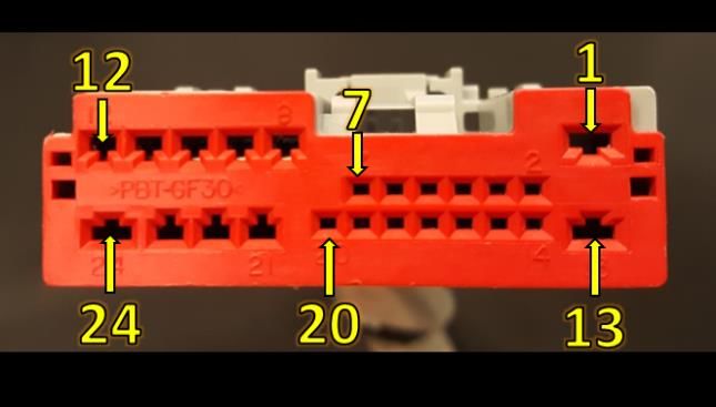
VSIM 16 - CAVITY GREEN CONNECTOR 2019

                                                                   Max

                                               Circuit
                                                         Wire
PIN              Upfitter VSIM Signal                            Current    Type of Signal                                                                        Function
                                                         Color
                                                                 (Amps)

 1    Not Used                                                     --                             Not Used

                                                                           Digital Signal Input
 2    Split Shaft PTO - digital input          W544       GY       --                             When grounded, signals the controller it's ok to initiate split shaft PTO.
                                                                           Switch to Ground

 3    Not Used                                                     --

      Rear Bulb Out Detection off - digital                                Digital Signal Input   When grounded, turns off rear (Turn/Tail/Brake/License/Reverse/CHMSL/Cargo) bulb fault detection: allows the use of rear LED's in
 4                                             W509      WH/BN     --
      input                                                                Switch to Ground       place of incandescent bulbs. May be grounded before or after disconnecting the vehicles OEM incandescent bulbs.

                                                                                                  NOTE: vehicle must have been built with PTO Prep option sales code LBN or LBV for this feature to operate. When grounded sets the
                                                                           Digital Signal Input   PTO Remote 1 RPM ( Set the desired RPM for this ciruit by using the instrument cluster programing screen, select: PTO/Remote/RPM
 5    PTO engine speed 1 - digital input       W541      GY/OG     --
                                                                           Switch to Ground       Preset 1 - then set the desired RPM); speed 1 overrides F425 @ 900 RPM and speeds 2 & 3: RPM up/down ramp rate is is
                                                                                                  programmable in commercial settings. If not programmed the default ramp rate is 200 RPM/sec.

                                                                                                  NOTE: vehicle must have been built with PTO Prep option sales code LBN or LBV for this feature to operate. When grounded sets the
                                                                           Digital Signal Input   PTO Remote 1 RPM ( Set the desired RPM for this ciruit by using the instrument cluster programing screen, select: PTO/Remote/RPM
 6    PTO engine speed 3 - digital input       W543      GY/YE     --
                                                                           Switch to Ground       Preset 1 - then set the desired RPM); speed 1 overrides F425 @ 900 RPM; is overridden by speeds 1 or 2; RPM up/down ramp rate is
                                                                                                  programmable in the settings. If not programmed the default ramp rate is 200 RPM/sec.

 7    Low Beam active signal - HSD output      W683      WH/BN     0.5         HSD Output         High side output is on when low beams are active

 8    Not Used                                                                                    Not Used

      E-Stop Signal (Vehicles with Remote                                  Digital Signal Input   On vehicles with Remote Ignition function activated, when this signal wire is connected to 12V+ will stop a running engine. **This
 9                                             W555      GN/DB
      Ignition feature turned on)                                          Switch to 12V Batt     input signal is not intended to prevent engine cranking or engine attempting to start by the key or remotely**

10    Not Used                                                                                    Not Used

                                                                                                   When grounded it commands the vehicle A/C system to be activated. If the A/C isn't on, this input will activate the A/C compressor
      HVAC - upfitter remote A/C select -                                  Digital Signal Input   and turn the vehicle HVAC blower to Low speed Once this circuit is activated (grounded) the vehicles blower speed control can be
11                                             W656       BU       0.5
      digital input                                                        Switch to Ground       used to control but the blower - A/C system cannot be turned completely off. When this circuit is deactivated (un-grounded), the
                                                                                                  vehicles A/C controls returns to normal operation.

      Separated rear tail lighting - digital                               Digital Signal Input
12                                             W546      BG/GY     --                             When grounded rear stop/turn lamps become turn on only (via CAN message)
      input                                                                Switch to Ground

                                                                                                  NOTE: vehicle must have been built with PTO Prep option sales code LBN or LBV for this feature to operate. When grounded sets the
                                                                           Digital Signal Input   PTO Remote 2 RPM ( Set the desired RPM for this cicuit by using the instrument cluster programing screen, select: PTO/Remote/RPM
13    PTO engine speed 2 - digital input       W542      GY/BN     --
                                                                           Switch to Ground       Preset 2 - then set the desired RPM); speed 2 overrides F425 @ 900 RPM and speed 3 but is overridden by speed 1; RPM up/down
                                                                                                  ramp rate is programmable in the settings. If not programmed the default ramp rate is 200 RPM/sec.

      Engine running Hour Meter - HSD
14                                             W522      DB/BG     0.5         HSD Output         Open circuit when engin RPM < 450, battery postive voltage (+12V) when RPM > 450.
      output

15    Park Lamp on HSD Output                  W699      WH/GN     0.5         HSD Output         Open circuit when Park Lamps are not on, battery postive voltage (+12V) when Park Lamps are on.

16    Not Used                                                                                    Not Used

3/1/2019                                                                                 VSIM Jumper 16 Cavity Green Connector 2019
                                                                                                                                                                                                                         All Rights Reserved

FCA US LLC - Body Builder Instruction                                                                                                                                                                                          8 of 16
VSIM Jumper 24 - CAVITY GRAY IN-LINE CONNECTOR                                           2019
                                                                               Max

                                                             Circuit
                                                                       Wire               Type of
 PIN                   Upfitter VSIM Signal                                  Current                                                                              Function
                                                                       Color              Signal
                                                                             (Amps)
  1    Not Used                                                                                         Not Used

  2    Hazard indicator on                                   W719      WH/BU    0.5     HSD Output      Open circuit when hazard flashers are off, battery positive voltage (+12V) when hazard flashers are selected.

  3    Transmission out of "Park"                            W504       BN      0.5     HSD Output      Open circuit when gear selector is in Park , battery positive voltage (+12V) when the gear selector is in any other position.

  4    Right Turn Signal on                                  W681      WH/DG    0.5     HSD Output      High side relay driver output on and blinks when right turn signals are on.

  5    PTO on indicator                                      W743      VT/BG     1      HSD Output      Open circuit when PTO circuit is not energized, battery positive voltage (+12V) when PTO circuit is energized.

  6    MIL lamp on                                           W540       DG      0.5     HSD Output      Open circuit when MIL is not illuminated battery positive voltage (+12V) when MIL is illuminated.

  7    Transmission "Park" position                          W700      YE/DB    0.5     LSD Output      Open circuit when gear selector is not in Park, grounded when in Park.

  8    Transmission "Neutral" position                       W701      DG/YE    0.5     LSD Output      Open circuit when gear selector is not in Neutral, grounded when in Neutral.

  9    HVAC - A/C Clutch engaged                             W652      BU/BN    0.5     LSD Output      Open circuit when A/C Clutch is not engaged, grounded when engaged.

 10    ** CAN communication CAN + 250 Kbaud J1939            W533      BN/DB            J1939 Bus (+) 125 Kbaud CAN+, use in conjunction with W534*, refer to J1939 spreadsheet for available messages.

 11    ** CAN communication CAN - 250 Kbaud J1939            W535      BN/BU    0.5     J1939 Bus (-)   125 Kbaud CAN-, use in conjunction with W532*, refer to J1939 spreadsheet for available messages.

 12    Transmission "Reverse" Position                       W702      DG/DB    0.5     LSD Output      Open circuit when gear selector is not in Reverse, grounded when in Reverse.

 13    Not Used                                                                                         Not Used

 14    HVAC - when A/C is selected via the dash switch       W689      BU/DG    0.5     LSD Output      Open circuit when A/C has not been selected, grounded when A/C has been selected.

 15    Not Used                                                                                         Not Used

 16    Transmission "Drive" Position                         W703      DG/BU    0.5     LSD Output      Open circuit when gear selector is not in Drive, grounded when in Drive.

 17    Any Door Ajar                                         W720      VT/OG    0.5     HSD Output      Open circuit when all the doors are closed, battery voltage (+12V) when any door is ajar.

 18    Passenger Seat Belt Not Latched - Only on 2500 (DJ)   W706      DG/GY    0.5     LSD Output      Open circuit when passenger seat belt is latched, grounded when passenger seat belt is not latched.

 19    Passenger Seat Occupied Signal - Only on 2500 (DJ)    W554      DG/VT    0.5     LSD Output      Open circuit when passenger seat is non occupied, grounded when passenger seat is occupied.

 20    Not Used                                                                                         Not Used

 21    Not Used                                                                                         Not Used

 22    Not Used                                                                                         Not Used

 23    Not Used                                                                                         Not Used

 24    Not Used                                                                                         Not Used

3/1/2019                                                                       VSIM Jumper 24 – Cavity In-Line Gray Connector 2019                                                                                All Rights Reserved

FCA US LLC - Body Builder Instruction                                                                                                                                                                                    9 of 16
2019 RAM Heavy Duty Truck - SAE J1939 Output Messages
  Parameter
                                                     Suspect                                               Transmission
    Group                                                                                        Source
            Parameter Group Name                    Parameter      Suspect Parameter Name                   Repetition  Transmission Type                    Ram Specific Information
   Number                                                                                        Address
                                                   Number (SPN)                                              Rate (ms)
    (PGN)
                                                                                                                                             ASR is RAM equivalent of Electronic Stability Control.
    61441   Electronic Brake Controller 1              561         ASR Engine Control Active       11          100            Cyclic         There is no differentiation between engine and braking
                                                                                                                                             control, both signals will be active at the same time.

                                                                                                                                             ASR is RAM equivalent of Electronic Stability Control.
    61441   Electronic Brake Controller 1              562         ASR Brake Control Active        11          100            Cyclic         There is no differentiation between engine and braking
                                                                                                                                             control, both signals will be active at the same time.

    61441   Electronic Brake Controller 1              563          Antilock Braking Active        11          100            Cyclic
                                                                                                                                             This signal will be active lamp indicator check that occurs
    61441   Electronic Brake Controller 1             1438        ABS Amber Warning Signal         11          100            Cyclic
                                                                                                                                             at key on from off.
    61443   Electronic Engine Controller 2             91         Accelerator Pedal Position 1     0           50             Cyclic
                                                                                                              speed
    61444   Electronic Engine Controller 1             190               Engine Speed              0                          Cyclic
                                                                                                            dependent
    61445   Electronic Transmission Controller 2       523        Transmission Current Gear        3           100            Cyclic         Functions only on Aisin Transmissions.
            Beltlock and Airbag Deactivation
    64791                                             4952          Driver Belt Lock Status        53          250            Cyclic
            Switch Information
            Beltlock and Airbag Deactivation
    64791                                             4953        Passenger Belt Lock Status       53          250            Cyclic
            Switch Information
    64932   PTO Drive Engagement                      3948        At Least One PTO Engaged         0           100            Cyclic
            Operators External Light Controls
    64972                                             2875            Hazard Light Switch          33         1000      Cyclic & On Change
            Message
    65088   Lighting Command                          2348        High Beam Headlight Data         33         1000      Cyclic & On Change

    65088   Lighting Command                          2350         Low Beam Headlight Data         33         1000      Cyclic & On Change

    65088   Lighting Command                          2368           Left Turn Signal Lights       33         1000      Cyclic & On Change

    65088   Lighting Command                          2370          Right Turn Signal Lights       33         1000      Cyclic & On Change

    65088   Lighting Command                          2372              Left Stop Light            33         1000      Cyclic & On Change

    65088   Lighting Command                          2374              Right Stop Light           33         1000      Cyclic & On Change

3/1/2019                                                                           VSIM J1939 SAE Output Messages                                                                           All Rights Reserved

FCA US LLC - Body Builder Instruction                                                                                                                                                           10 of 16
2019 RAM Heavy Duty Truck - SAE J1939 Output Messages
Parameter Suspect Source Transmission
Parameter Group Name Suspect Parameter Name Transmission Type Ram Specific Information
Group Parameter Address Repetition
65088 Lighting Command 2376 Center Stop Light 33 1000 Cyclic & On Change
65088 Lighting Command 2378 Tractor Marker Light 33 1000 Cyclic & On Change
65088 Lighting Command 2382 Tractor Clearance Light 33 1000 Cyclic & On Change
Back - Up Light and Alarm
65088 Lighting Command 2392 33 1000 Cyclic & On Change
Horn
65088 Lighting Command 2404 Running Light 33 1000 Cyclic & On Change
High Resolution Total Vehicle
65217 High Resolution Vehicle Distance 917 33 1000 Cyclic & On Change
Distance
Flash Malfunction Indicator
65226 Active Diagnostic Trouble Codes 3038 (flash) 0 100 Cyclic
Lamp
Malfunction Indicator Lamp
65226 Active Diagnostic Trouble Codes 1213 (on/off) 0 100 Cyclic
Status
65248 Vehicle Distance 245 Total Vehicle Distance 33 100 Cyclic
Vehicle Identification
65260 Vehicle Identification 237 33 ~ 300 Cyclic Timing is not exact due to bus translations.
Number (VIN)
65262 EngineTemperature 1 110 Engine Coolant Temperature 0 500 Cyclic
65263 Engine Fluid Level/Pressure 1 100 Engine Oil Pressure 0 200 Cyclic
Engine Speed, will not reflect actual PTO shaft speed when
65264 Power Takeoff Information 186 Power Takeoff Speed 0 100 Cyclic
the torque converter is unlocked.
65265 Cruise Control/Vehicle Speed 70 Parking Brake Switch 0 100 Cyclic
65265 Cruise Control/Vehicle Speed 84 Wheel-Based Vehicle Speed 0 100 Cyclic
The last set speed value is broadcast in this message
65265 Cruise Control/Vehicle Speed 86 Cruise Control Set Speed 0 100 Cyclic
whether the cruise control is active or not.
When the value of this signal is '01' cruise control system
65265 Cruise Control/Vehicle Speed 595 Cruise Control Active 0 100 Cyclic
is actively controlling vehicle speed.
When the value of this signal is '01' the cruise control
65265 Cruise Control/Vehicle Speed 596 Cruise Control Enable Switch 0 100 Cyclic
enable switch is depressed.
65265 Cruise Control/Vehicle Speed 597 Brake Switch 0 100 Cyclic
VSIM J1939 SAE Output Messages All Rights Reserved
3/1/2019
FCA US LLC - Body Builder Instruction 11 of 162019 RAM Heavy Duty Truck - SAE J1939 Output Messages
Parameter Suspect Source Transmission
Parameter Group Name Suspect Parameter Name Transmission Type Ram Specific Information
Group Parameter Address Repetition
When the value of this signal is '01' the cruise control
65265 Cruise Control/Vehicle Speed 596 Cruise Control Enable Switch 0 100 Cyclic
enable switch is depressed.
65265 Cruise Control/Vehicle Speed 597 Brake Switch 0 100 Cyclic
65265 Cruise Control/Vehicle Speed 599 Cruise Control Set Switch 0 100 Cyclic
65265 Cruise Control/Vehicle Speed 600 Cruise Control Coast Switch 0 100 Cyclic
Cruise Control Resume
65265 Cruise Control/Vehicle Speed 601 0 100 Cyclic
Switch
Cruise Control Accelerate
65265 Cruise Control/Vehicle Speed 602 0 100 Cyclic
Switch
Power Takeoff Governor
65265 Cruise Control/Vehicle Speed 976 0 100 Cyclic
State
65266 Fuel Economy (Liquid) 183 Engine Fuel Rate 0 100 Cyclic
65269 Ambient Conditions 108 Barometric Pressure 33 100 Cyclic
65269 Ambient Conditions 171 Ambient Air Temperature 33 100 Cyclic & On Change
Engine Air Intake
65269 Ambient Conditions 172 33 100 Cyclic
Temperature
65271 Vehicle Electrical Power 1 167 Charging System Potential 33 1000 Cyclic & On Change
Transmission Oil
65272 Transmission Fluids 1 177 3 1000 Cyclic & On Change
Temperature
65274 Brakes 619 Parking Brake Actuator 33 1000 Cyclic
65276 Dash Display 96 Fuel Level 33 1000 Cyclic & On Change
64933 Door Control 2 3412 Lock Status Of Door 1 33 100 Cyclic
64933 Door Control 2 3413 Open Status Of Door 1 33 100 Cyclic
64933 Door Control 2 3415 Lock Status Of Door 2 33 100 Cyclic
64933 Door Control 2 3416 Open Status Of Door 2 33 100 Cyclic
VSIM J1939 SAE Output Messages All Rights Reserved
3/1/2019
FCA US LLC - Body Builder Instruction 12 of 162019 RAM Heavy Duty Truck - SAE J1939 Output Messages
Parameter
Suspect Transmission
Group Source
Parameter Group Name Parameter Suspect Parameter Name Repetition Transmission Type Ram Specific Information
Number Address
Number (SPN) Rate (ms)
(PGN)
64933 Door Control 2 3418 Lock Status Of Door 3 33 100 Cyclic
64933 Door Control 2 3419 Open Status Of Door 3 33 100 Cyclic
64933 Door Control 2 3421 Lock Status Of Door 4 33 100 Cyclic
64933 Door Control 2 3422 Open Status Of Door 4 33 100 Cyclic
64933 Door Control 2 3424 Lock Status Of Door 5 33 100 Cyclic
64933 Door Control 2 3425 Open Status Of Door 5 33 100 Cyclic
Illumination Brightness
53248 Cab Illumination Message 1487 33 1000 Cyclic & On Change
Percent
Aftertreatment 1 Diesel Exhaust Fluid Aftertreatment 1 Diesel
65110 1761 0 1000 Cyclic & On Change
Tank 1 Information Exhaust Fluid Tank 1 Level
Engine Oil Pressure Low
64773 Direct Lamp Control Data 1 5099 33 1000 Cyclic
Lamp Data
65266 Fuel Economy (Liquid) 184 Instanteneous Fuel Economy 0 100 Cyclic
65253 Hours 247 Eng Total Hours Of Operation 0 1000 Cyclic
65254 Time/Date 961 Hour 33 1000 Cyclic
65254 Time/Date 960 Minutes 33 1000 Cyclic
Used to indicate the actual
65102 Position of Doors 1821 33 100 Cyclic
position of the doors.
All Rights Reserved
3/1/2019 VSIM J1939 SAE Output Messages
FCA US LLC - Body Builder Instruction 13 of 16New for 2019 J1939 RPM control: RPM can now be controlled over CAN using through the J1939 VSIM interface while PTO is active. Signal information is
in the chart below. This can be done following these steps:
o PTO must be in remote mode with J1939 selected as the RPM control
o PTO is still enabled though F425 circuit
o RPM is commanded through PGN 0, Torque/Speed Control 1 (TSC1)
TSC1 message definition follows SAE standard for J1939
SPN 695 shall be set to 0x1 when control of RPM is desired, and 0x0 otherwise
SPN 898 shall be set to the desired RPM within 900-2000 for AUX drive and 1200-2400 for Split Shaft.
Input values are handled as follows
Aux Drive
o 0x0000 - 0x0384 = 900 RPM
o 0x0384 – 0x07D0 = desired RPM from 900-2000
o 0x07D0 – 0xFFFE = 2000 RPM
o 0xFFFF = 900 RPM
Split Shaft
o 0x0000 - 0x04B0 = 1200 RPM
o 0x04B0 – 0x0960 = desired RPM from 1200-2400
o 0x0960 – 0xFFFE = 2400 RPM (2000 AUX drive)
o 0xFFFF = 1200 RPM
Maximum engine RPM/s response to requested set point is defined by the ramp rate selection in the Commercial Settings. See PTO menu
section.
All other SPNs that are part of PGN 0 are don’t care
o Vehicle status information such as current engine RPM can be obtained from the J1939 VSIM bus.
2019 RAM Heavy Duty Truck - SAE J1939 Input signal from external device to VSIM to vehicle systems
Parameter
Suspect Transmission
Group Source
Parameter Group Name Parameter Suspect Parameter Name Repetition Transmission Type Ram Specific Information
Number Address
Number (SPN) Rate (ms)
(PGN)
Engine Override Control Engine Override Control Mode: The override control mode defines
0 TSC1 695 N/A 1000 Cyclic & On Change which sort of command is used.
mode
Parameter provided to the engine from external sources in the
torque/speed control message. This is the engine speed which the
0 TSC1 898 Engine Requested Speed N/A 1000 Cyclic & On Change engine is expected to operate at if the speed control mode is active or
the engine speed which the engine is not expected to exceed if the
speed limit mode is active.
2019 RPM J1939 Signals/Commands from External Device to VSIM to Vehicle Systems (Input Signals)
All Rights Reserved
3/4/2019
FCA US LLC - Body Builder Instruction 14 of 162019 RAM Heavy Duty Truck Specific J1939 Signals from Vehicle Systems to VSIM to external device (output signals)
Parameter
Suspect Starting Transmission
Group Parameter Group Suspect Parameter Source Size Data Ram Specific
Parameter Position Data Description Data Resolution Repetition Rate Transmission Type Signal Description
Number Name Name Address (bits) Range Information
Number (SPN) (bit) (ms)
(PGN)
00' off Cyclic & On Active when A/C clutch is
65280 Chrysler Interior 100000 A/C Clutch Engaged 33 0 1 1 bit = 2 states 0 to 1 1000
01' clutch engaged Change engaged
Active when A/C is
00' off Cyclic & On
65280 Chrysler Interior 100001 A/C Select 33 1 1 1 bit = 2 states 0 to 1 1000 requested either by
01' A/C requested Change
VSIM, MTC or ATC HVAC
'000' IGN_LK
'011' IGN_OFF_ACC Provides status of
Cyclic & On
65280 Chrysler Interior 100002 Ignition Position 33 3 3 '100 'IGN_RUN 3 bits = 8 states 0 to 7 1000 igntition: off, accessory,
Change
'101' IGN_START run, start
'111' SNA
00' no Airbag
deployed Cyclic & On Follow "any impact"
65280 Chrysler Interior 100003 Air Bag Deployed 33 2 1 1 bit = 2 states 0 to 1 1000
01' any Airbag Change signal from ORC
deployed
00' not occupied
Follows Passenger
Passenger Occupant '01' occupied Cyclic & On Ram 1500 and
65280 Chrysler Interior 100004 33 6 2 2 bits = 4 states 0 to 3 1000 Occupant detect sensor
Detection System '10' error Change 2500 only.
Sts from ORC
'11' sna
If X = 0 then y = 0
If X=1 then y shall toggle
Chrysler Exterior Cyclic & On Follows duty cycle of Wig Wags
62581 100005 Front Wig Wag 33 0 1 between 1 and 0 with 1 bit = 2 states 0 to 1 1000 like VSIM output
Lights f=1.5Hz and duty cycle = Change
50 %
If X = 0 then y = 0
If X=1 then y shall toggle
Chrysler Exterior Cyclic & On Follows duty cycle of Wig Wags
62581 100006 Rear Wig Wag 33 1 1 between 1 and 0 with 1 bit = 2 states 0 to 1 1000 like VSIM output
Lights f=1.5Hz and duty cycle = Change
50 %
Chrysler Exterior 00' under 25 mph Cyclic & On Active when vehicle
65281 100007 Howler Siren Disable 33 3 1 1 bit = 2 states 0 to 1 1000
Lights and Horn 01' over 25 mph Change speed is over 25mph
Chrysler Exterior 00' Horn off Cyclic & On
65281 100008 Horn 33 2 1 1 bit = 2 states 0 to 1 1000
Lights and Horn 01' Horn on Change
00' no door lock
Chrysler Doors command Cyclic & On
65282 100009 Door Lock Command 33 0 1 1 bit = 2 states 0 to 1 1000 Follow VSIM Logic
and Locks 01' door lock Change
command active
00' no door unlock Input signal from
Chrysler Doors Door Unlock command external device
65282 100010 33 1 1 1 bit = 2 states 0 to 1 1000 Follow VSIM Logic
and Locks Command 01' door unlock to VSIM to
command active vehicle systems
All Rights Reserved
3/1/2019 2019 Ram Heavy Duty Truck Specific J939 Message from VSIM to External Device
FCA US LLC - Body Builder Instruction 15 of 162019 RAM Heavy Duty Truck Specific J1939 Input signal from external device to VSIM to vehicle systems (input signals)
Parameter
Suspect Starting Transmission
Group Parameter Group Suspect Parameter Source Size Data Ram Specific
Parameter Position Data Description Data Resolution Repetition Rate Transmission Type Signal Description
Number Name Name Address (bits) Range Information
Number (SPN) (bit) (ms)
(PGN)
Chrysler Interior 0 No Command Cyclic & On
65283
Command
2551 CHY_INT_CMD.ACSelect N/A 0 1 1 Command
1 bit = 2 states 0 to 1 1000 Command A/C select on
Change
Chrysler Interior 0 No Command Cyclic & On Command to mute all
65283
Command
2551 CHY_INT_CMD.RadioMute N/A 1 1 1 Command
1 bit = 2 states 0 to 1 1000 entertainment audio
Change
Chrysler Exterior
CHY_ExLH_CMD. 0 No Command Cyclic & On
65284 Lights and Horn 2551 RrWigWag
N/A 0 1 1 Command
1 bit = 2 states 0 to 1 1000 Command rear wig wags on
Command Change
Chrysler Exterior
CHY_ExLH_CMD. 0 No Command Cyclic & On
65284 Lights and Horn 2551 FtWigWag
N/A 1 1 1 Command
0 to 1 1000 Command front wig wags on
Command Change
RKE horn
function can
Chrysler Exterior
0 No Command Cyclic & On Command to mute all horn only be
65284 Lights and Horn 2551 CHY_ExLH_CMD.HornMute N/A 2 1 1 Command
1 bit = 2 states 0 to 1 1000 requests.
Command Change disabled via the
menu settings
in the Radio
Chrysler Doors CHY_DrLk. 0 No Command Cyclic & On
65285
and Locks
2551 LockCommand*
N/A 0 1 1 Command
1 bit = 2 states 0 to 1 1000 Command to lock door
Change
Chrysler Doors CHY_DrLk.. 0 No Command Cyclic & On
65285
and Locks
2551 UnLockCommand*
N/A 1 1 1 Command
1 bit = 2 states 0 to 1 1000 Command to unlock door
Change
2019 Ram Heavy Duty Truck Specific J1939 Signals/Commands from External
Device to VSIM to Vehicle Systems (Input Signals)
All Rights Reserved
3/1/2019
FCA US LLC - Body Builder Instruction 16 of 16You can also read