VENU1012V(A17) USER MANUAL - DIGITAL FLAT PANEL DETECTOR - KONICA MINOLTA HEALTHCARE
←
→
Page content transcription
If your browser does not render page correctly, please read the page content below
Digital Flat Panel Detector

Venu1012V(A17)
User Manual

Version   :A0
Doc ID    :060-201-03
Release Date::2020.12.30

Medical device registration certificate no:

Registered product standard no:

Before operating, please read this user manual and pay attention to all safety precautions.
Please ensure that this user's manual is properly maintained so that it can be accessed at any
time (reserve).
Please use it correctly on the basis of full understanding of the content.
To Customers

    To Customers
             Congratulations on your purchase of the Fixed Digital Flat Panel (hereinafter
             referred to as VENU1012V) which is manufactured by iRay Technology Co.Ltd.
             (Hereinafter referred to as iRay).

            Please take time to read this user guide in order to utilize the product effectively.
            We hope you enjoy the experience with iRay VENU1012V.

             If you have any questions or suggestions, please feel free to contact us.

                                             Service Office

                                         Tel: +86 21 50720560

                                         Fax: +86 21 50720561

                                    E-mail: service@iraygroup.com

                  Location: 2F, Building 9, No.590, Ruiqing Rd, Pudong, Shanghai,

Notes on usage and management of the equipment
                        1.   Read all of the instructions in the user guide before your operation.
                             Give particular attention to all safety precautions.

                        2.   Only a physician or a legally certified operator should use this
                             product.

                        3.   Maintenance personnel should maintain the equipment in a safe and
                             operable condition.

                        4.   Use only computers and image display monitors complying with IEC
                             60601-1 or IEC 60950-1. For details, consult our sales
                             representative or local iRay dealer.

                        5.   Use only the dedicated cables. Do not use any cables other than
                             those supplied with this product.

                        6.   Request your sales representative or local iRay dealer to install this
                             product。

Caring for your environment
           This symbol indicates that this product is not to be disposed of with your residential
           or commercial waste.

 User Manual of Venu1012V                                                                   1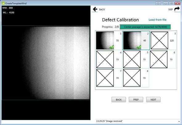
Flat Panel Detector Venu1012V

Recycling iRay Equipment
          Please do not dispose of this product with your residential or commercial waste.
          Improper handling of this type of waste could have a negative impact on health and
          on the environment. Some countries or regions, such as the European Union, have
          set up systems to collect and recycle electrical or electronic waste items. Contact
          your local authorities for information about practices established in your region. If
          collection systems are not available, call iRay Customer Service for assistance.

Disclaimer
          1.   iRay shall not be liable to the purchaser of this product or third parties for any
               damage, loss, or injury incurred by purchaser or third parties as a result of fire,
               earthquake, any accident, misuse or abuse of this product.

          2.   iRay shall not be liable to any damage, loss, or injury arising from unauthorized
               modifications, repairs, or alterations to this product or failure to strictly comply
               with iRay’s operating and maintenance instructions.

          3.   iRay shall not be liable for any damage or loss arising from the use of any
               options or consumable products other than those dedicated as Original iRay
               Products by iRay Technology.

          4.   It is the responsibilities of the user/attending physicians for maintaining the
               privacy of image data and providing medical care services. iRay shall not be
               responsible for the legality of image processing, reading and storage nor it
               shall be responsible for loss of image data for any reason.

          5.   Information regarding specification, compositions, and appearance of this
               product is subject to change without prior notice.

          6.   Venu1012V has no applied parts. Be sure to check the connection of all the
               parts are set properly & check the detector is kept in insulated cover that
               operator or patient can’t touch the detector directly before powered up.

          7.   The voltage DIP, interruption or variation of the system power supply may
               have impact on Venu1012V. So the uninterruptible power supply should be
               considered.

          8.   Venu1012V is forbidden to use under oxygen-enriched conditions.

          9.   Venu1012V is forbidden to use near flammable objects.

Copyright
          All rights reserved

          No part of this publication may be reproduced in any form or by any means without
          the written permission of iRay. The information contained herein is designed only
          for use with iRay Venu1012V.

Trademarks
          The iRay name and iRay logo are registered trademarks of iRay Technology Co.
          Ltd.

2                                                                           User Manual of Venu1012V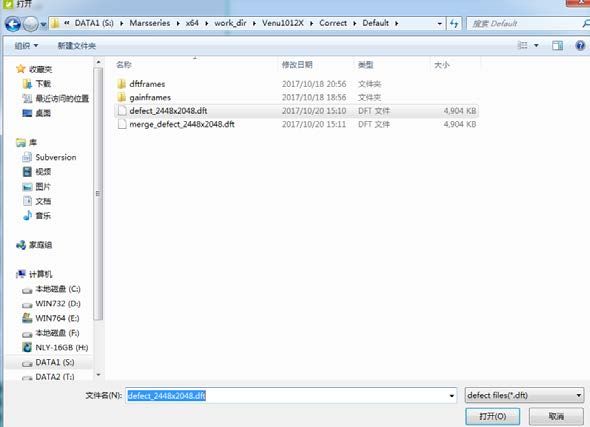
To Customers

Symbols and Conventions
The following symbols and conventions are used throughout the user guide.

                                   This symbol is used to identify conditions under
                                   which improper use of the product may cause death
                                   or serious personal injury.

                                   This notice is used to identify conditions under
                                   which improper use of the product may cause minor
                                    personal injury.

                                   This notice is used to identify conditions under
                                   which improper use of the product may cause
                                   property damage.

                                   This is used to indicate a prohibited operation.

                                   This is used to indicate an action that must be
                                   performed.

                                   This is used to indicate important operations and
                                   restrictions.

                                   This is used to indicate operations for reference and
                                   complementary information.

 User Manual of Venu1012V                                                                  3
Flat Panel Detector Venu1012V

Labels and markings on the equipment
The contents of the labels and markings on iRay Venu1012V product are indicated below:

          图 标                                        含 义

                        Caution: please refer to the instructions in the user manual.

                        This symbol is used to indicate that the equipment has passed

                        CE testing and it is followed by the CE Notified Body number.

                        This symbol is used to identify the manufacturer’s series
                        number which is after, below or adjacent to the symbol. The s
                        eries number of iRay products is usually made of thirteen digits
                        as shown below:

                         A1A2A3A4       C1C2 M     DD Y XXX

                                                                          Numerical Order

                                                                          Year

                                                                          Date

                                                                          Month

                                                                          Version

                                                                         Product Code

                        This symbol is used to indicate the name and address of the
                         manufacturer.

                        Manufacturing date of this product.

                        Expiring date of this product.

                        This symbol is used to indicate the name and address of iRay
                        authorized representative in the European region.

4                                                                          User Manual of Venu1012V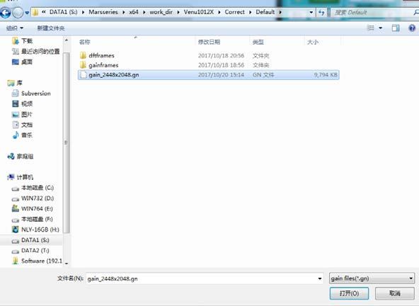
To Customers

                           This symbol is used to indicate consultation of the user guide
                           for general information.

                           This product is not to be disposed of with your residential or
                           commercial waste.

                           Safety Signs: please refer to the user guide for safety
                           instructions.

                           Safety Signs:Dangerous Voltage.

                           This symbol indicates load limit.

                           Handled with care.

                           This symbol is used to indicate the operational temperature
                           limits.

                           This symbol is used to indicate the storage temperature limits.

                           Package symbol, fragile.

                           Package symbol, keep away from sunlight.

                           Package symbol, keep dry.

                           Package symbol, this symbol is used to indicate the humidity
                           limits.

User Manual of Venu1012V                                                                     5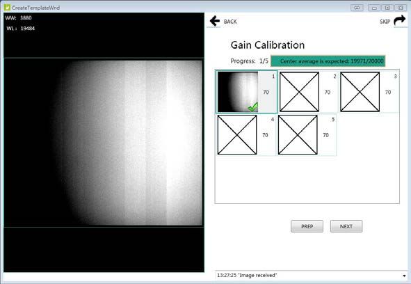
Flat Panel Detector Venu1012V

                      Package symbol, keep the equipment up right.

                      Package symbol, do not roll the transportation package.

                      Package symbol, this symbol is used to indicate stacking limit
                      number.

6                                                                       User Manual of Venu1012V
Contents

Contents

TO CUSTOMERS ................................................................................................................................ 1

CONTENTS ......................................................................................................................................... 7

1      SAFETY INFORMATION .......................................................................................................... 10

             1.1        SAFETY PRECAUTIONS ................................................................................................... 10
             1.2        NOTES FOR USING ......................................................................................................... 15

2      GENERAL DESCRIPTION ....................................................................................................... 18

             2.1        SCOPE ............................................................................................................................ 18
             2.2        MODEL ............................................................................................................................ 18
             2.3        CHARACTERISTIC............................................................................................................ 19
             2.4        INTENDED USE ................................................................................................................ 19
             2.5        PRODUCT SPECIFICATION .............................................................................................. 19
             2.6        ENVIRONMENT REQUIREMENTS...................................................................................... 20
             2.7        PRODUCT COMPONENTS................................................................................................ 21
             2.8        COMPONENTS DESCRIPTION.......................................................................................... 22

3      SOFTWARE INSTRUCTIONS ........................................................................................................... 26

             3.1        SYSTEM REQUIREMENT.................................................................................................. 26
             3.2        ENVIRONMENT ................................................................................................................ 26
             3.3        W IRED CONNECTION ...................................................................................................... 26
             3.4        NETWORK CONFIGURATION ........................................................................................... 29
             3.5        USER INTERFACE.................................................................................................................. 30
             3.6        CALIBRATION ...................................................................................................................... 31

4      OPERATION .............................................................................................................................. 41

             4.1        STEPS FOR ACQUIRING IMAGE................................................................................................. 41
             4.2        INNER MODE OPERATION............................................................................................... 41
             4.3        FREESYNC MODE OPERATION ....................................................................................... 44
             4.4        AFTER USE...................................................................................................................... 46

5      REGULATORY INFORMATION .............................................................................................. 48

             5.1        MEDICAL EQUIPMENT SAFETY STANDARDS .................................................................... 48
             5.2        GUIDANCE AND MANUFACTURE’S DECLARATION FOR EMC ......................................... 49
             5.3        PRODUCT LABEL............................................................................................................. 52

6      SERVICE INFORMATION ........................................................................................................ 54

             6.1        PRODUCT LIFETIME ........................................................................................................ 54

    User Manual of Venu1012V                                                                                                                       7
Flat Panel Detector Venu1012V

          6.2    REGULAR INSPECTION AND MAINTENANCE ................................................................... 54
          6.3    REPAIR............................................................................................................................ 54

APPENDIX A INFORMATION OF MANUFACTURES .................................................................. 56

8                                                                                                                  User Manual of Venu1012V
1. Safety Information
1 SAFETY INFORMATION
1.1 SAFETY PRECAUTIONS ................................................................................................... 10
1.2 NOTES FOR USING ......................................................................................................... 15
User Manual of Venu1012V 9Flat Panel Detector Venu1012V
1 Safety Information
1.1 Safety Precautions
Follow these safeguards and properly use the equipment to prevent injury and damage to
any equipment/data.
WARNING
Installation and Do not use or store the equipment near flammable
chemicals such as alcohol, thinner, benzene, etc.
environment of
use If chemicals are spilled or evaporate, it may result in fire or
electric shock through contact with electric parts inside the
equipment. Also, some disinfectants are flammable. Be
sure to take care when using them.
Do not connect the equipment with anything other than
specified.
Doing so may result in fire or electric shock.
All the patients with active implantable medical
devices should be kept away from the equipment.
Power supply Do not operate the equipment using any type of power
supply other than the one indicated on the rating label.
Otherwise, it may result in fire or electric shock.
Do not handle the equipment with wet hands.
You may experience electric shock that could result in
death or serious injury.
Do not place heavy object such as medical equipment
on cables and cords. Do not pull, bend, bundle, or step
on them to prevent their sheath from being damaged,
and do not alter them neither.
Doing so may damage the cords which could result in fire
or electric shock.
Do not supply power to more than one piece of
equipment using the same AC outlet.
Doing so may result in fire or electric shock.
Do not turn ON the system power when condensation
has formed on the equipment.
Doing so may result in fire or electric shock.
10 User Manual of Venu1012V1. Safety Information
Power supply Do not connect a multiple portable socket-outlet or
extension cord to the system.
Doing so may result in fire or electric shock.
To avoid the risk of electric shock, this equipment
must only be connected to power supply with
protective earth.
Not doing so may result in fire or electric shock.
Securely plug the power cord into the AC outlet.
If contact failure occurs, or if metal objects come into
contact with the exposed metal prongs of the plug, fire or
electric shock may result.
Be sure to turn OFF the power to each piece of
equipment before connecting or disconnecting the
cords.
Otherwise, you may get an electric shock that could result
in death or serious injury.
Be sure to hold the plug or connector to disconnect
the cord.
If you pull the cord, the core wire may be damaged,
resulting in fire or electric shock.
WARNING
Handling Never disassemble or modify the equipment. No
modification of this equipment is allowed. Parts of the
VENU1012V that are not serviced or maintained while
in use with the patient.
Doing so may result in fire or electric shock. Also, since the
equipment incorporates parts that may cause electric shock
as well as other hazardous parts, touching them may cause
death or serious injury.
Do not place anything on top of the equipment.
The object may fall and cause an injury. Also, if metal
objects such as needles or clips fall into the equipment, or if
liquid is spilled, it may result in fire or electric shock.
Do not hit or drop the equipment.
The equipment may be damaged if it receives a strong jolt,
which may result in fire or electric shock if the equipment is
used without being repaired.
Do not put the equipment and pointed objects
together.
The equipment may be damaged. If so, the equipment
should be used in bucky.
User Manual of Venu1012V 11Flat Panel Detector Venu1012V
Have the patient take a fixed posture and do not let the
patient touch parts unnecessarily.
If the patient touches connectors or switches, it may result
in electric shock or malfunction of the equipment.
When a problem Should any of the following occurs, immediately
unplug the power cord of Control Box, and contact
occurs your sales representative or local iRay dealer:
When there is smoke, an odd smell or abnormal sound.
When liquid has been spilled into the equipment or a metal
object has entered through an opening.
When the equipment has been dropped and damaged.
Maintenance and Please turn OFF the power of the equipment and
unplug the power cord of adaptor before cleaning.
inspection
NEVER use alcohol, ether and other flammable
cleaning agent for safety. NEVER use methanol,
benzene, acid and base because they will erode the
equipment.
DON'T dip the equipment into the liquid.
Please make sure that the equipment's surface & plugs
are dry before turning ON.
Otherwise, it may result in fire or electric shock.
Clean the plug of the power cord periodically by
unplugging it from the AC outlet and removing dust or
dirt from the plug, its periphery and AC outlet with a
dry cloth.
If the cord is kept plugged in for a long time in a dusty,
humid or sooty place, dust around the plug will attract
moisture; this could cause insulation failure that may result
in a fire.
For safety reasons, be sure to turn OFF the power to
each piece of equipment when performing inspections
indicated in this manual.
Otherwise, electric shocks may occur.
12 User Manual of Venu1012V1. Safety Information
CAUTION
Installation and Do not install the equipment in any of the locations
listed below. Doing so may result in failure,
environment of malfunction, equipment falling, fire or injury.
use
Close to facilities where water is used
Where it will be exposed to direct sunlight
Close to the air outlet of an air-conditioner or ventilation
equipment
Close to heat source such as a heater
Where the power supply is unstable
In a dusty environment
In a saline or sulfurous environment
Where temperature or humidity is high
Where there is freezing or condensation
In areas prone to vibration
On an incline or in an unstable area
Take care that cables do not become tangled during
use. Also, be careful not to get your feet caught by
cable.
Otherwise, it may cause a malfunction of the equipment or
injury of the user due to tripping over the cable.
Power supply Always connect the three-core power cord plug to a
grounded AC power outlet.
To make it easy to disconnect the plug at any time,
avoid putting any obstacles near the outlet. Otherwise,
it may not be possible to disconnect the plug in an
emergency.
Be sure to ground the equipment to an indoor
grounded connector. Also, be sure to connect all the
grounds for the system to a common ground.
Do not use any power source other than the one
provided with this equipment.
Otherwise, fire or electric shock may be caused due to
leakage.
User Manual of Venu1012V 13Flat Panel Detector Venu1012V
Handling Do not spill liquid or chemicals onto the equipment. In
case the patient is injured, it is not allowed to contact
with blood or other body fluids.
Doing so may result in fire or electric shock.
In such a situation, protect the equipment with a disposable
cover as necessary.
Turn OFF the power and pull out the plug to each piece
of equipment for safety when not used.
CAUTION
Handling Handle the equipment carefully.
Do not submerge the equipment in water.
The internal image sensor may be damaged if
something hits against it or it is dropped.
Do not place excessive weight on the equipment.
Be sure to use the equipment on a protected foam.
Otherwise, the internal image sensor may be damaged.
Be sure to securely hold the detector while using it in
upright positions. Otherwise, the detector may fall
over, resulting in injury to the user or patient, or may
flip over, resulting in damage to the inner device.
Keep the same load (same pressure) on the detector when
acquiring the image. Or the image will be incorrect.
CAUTION
Do not close to fire, do not use in high temperature
Do not invert positive and negative pole
Do not contact with metal in case of short circuit
14 User Manual of Venu1012V1. Safety Information
1.2 Notes for Using
When using the product, take the following precautions. Otherwise, problems may occur
and the product may not function correctly.
Before exposure
Be sure to check the connection of all the parts are set properly & check the
detector is kept in insulated cover that operator or patient can’t touch the
detector directly before powered up.
Be sure to check the product daily and confirm it work properly.
Sudden heating of the room in cold areas will cause condensation on the product.
In this case, wait until the condensation evaporates before performing an
exposure. If it is used when condensation is formed, problems may occur in the
quality of captured images. When an air-conditioner is used, be sure to
raise/lower the temperature gradually to prevent condensation.
The product should be warmed up for 15 minutes before exposure or updating the
gain map and defect map.
Make sure exposure rate is over 900nGy/s @70KV.
Make sure wave form of the energy going to the X ray tube is square not pulse.
Be cautious with circumstance that someone has radio isotope recently injected
into them, it may cause panel transmit image without x ray.
During exposure
Do not move Power Cable or Ethernet Cable during exposure, or it may cause
image noise or artifacts, even incorrect images.
Do not use the product near the equipment generating a strong magnetic field.
Otherwise, it may cause image noise, artifacts or even incorrect images.
After Usage
After every examination, wipe the patient contact surfaces with disinfectants such
as ethanol, to prevent the risk of infection. For details on how to sterilize, consult a
specialist.
Do not spray the product directly with disinfectants or detergents.
Wipe it with a cloth slightly damped with a neutral detergent. Do not use solvents
such as alcohol, benzene and acid. Doing so may damage the surface of the
product.
It’s recommended to use a waterproof non-woven cover as the isolated layer
User Manual of Venu1012V 15Flat Panel Detector Venu1012V
between product and the blooding patient.
16 User Manual of Venu1012V2. General Description
2 GENERAL DESCRIPTION
2.1 SCOPE ............................................................................................................................ 18
2.2 MODEL ............................................................................................................................ 18
2.3 CHARACTERISTIC............................................................................................................ 19
2.4 INTENDED USE ................................................................................................................ 19
2.5 PRODUCT SPECIFICATION .............................................................................................. 19
2.6 ENVIRONMENT REQUIREMENTS...................................................................................... 20
2.7 PRODUCT COMPONENTS................................................................................................ 21
2.8 COMPONENTS DESCRIPTION.......................................................................................... 22
User Manual of Venu1012V 17Flat Panel Detector Venu1012V
2 General Description
Venu1012V is a digital X-ray flat panel detector based on amorphous silicon thin-film
transistor technologies. It is developed to provide the highest quality of radiographic image,
which contains an active matrix of 2000×2400 with 125um pixel pitch.
2.1 Scope
This manual contains information about the Venu1012V. Information in the manual,
including the illustrations, is based on prototype. If your configuration does not have any of
these items, information about these items does not apply to your panel.
Figure 3.1.1
2.2 Model
Venu □ □ □
Model: TSI
Product Application: V series
Product dimension: 1012, 10inch×12inch
Product series: Venu
18 User Manual of Venu1012V2. General Description
2.3 Characteristic
Static flat panel detector used for general radiography.
Sync-shot exposure trigger
CsI scintillation screen
2.4 Intended use
Venu1012V serial Digital Flat Panel Detector is indicated for digital imaging solution
designed for providing general radiographic diagnosis for podiatry use. It is intended to
replace radiographic film/screen systems in general-purpose diagnostic procedures.
This panel is not intended for mammography, and prohibited for pregnant women and
children.
According to the Venu1012V intended use and the result of risk management, identifying
and describing the essential performance as the following:
a) To get image of dark field, the Venu1012V shall not be influenced to the imaging
acquisition;
b) To keep the data transmission function, the Venu1012V shall not be influenced to the
data and signal transmission.
2.5 Product Specification
Item Specification
Scintillator CsI-TSI
Effective area 250mm x 300mm
Pixel matrix 2048*2448 (row*column)
Pixel matrix (effective) 2000x2400 (row*column)
Pixel pitch (resolution) 125um
AD conversion 16bit
Trigger mode Inner, Freesync
The length of the X-ray window Typ. ≤ 1s
Image Acquisition Time Preview Time: Typ. 3s
Full image Time: Typ. 6s
Cycle Time 9s without image processing
Image Transfer Gigabit Ethernet
User Manual of Venu1012V 19Flat Panel Detector Venu1012V
Used kV 45kV to 55kV
Power Consumption Max. 20W
Weight 2.5kg
Degrees of protection provided by
IPX0
enclosure
2.6 Environment requirements
2.6.1 Operation requirements
Item Specification
Min 5 °C
Temperature
Max 35°C
Temperature variation Max ± 0.5 °C / min
Humidity Min 30 %RH
(no condensing) Max 80 %RH
Min 700 mbar
Pressure
Max 1060 mbar
Altitude Max 3000m
2.6.2 Transport and storage requirements
Item Specification
Min -10 °C
Temperature
Max 55°C
Temperature variation Max ± 1°C / min
Humidity Min 10 %RH
(no condensing) Max 90 %RH
Min 700 mbar
Pressure
Max 1060 mbar
Altitude Max 3000m
20 User Manual of Venu1012V2. General Description
2.7 Product Components
Item Description
1pcs
Venu1012V Detector
Main Unit
with Detector Cable
The Detector Cable is
replaceable.
Medical Adapter 1 pcs
DC 24V
Gigabit Ethernet 1pcs
Cable 3m
1 pcs
AC Power Cable
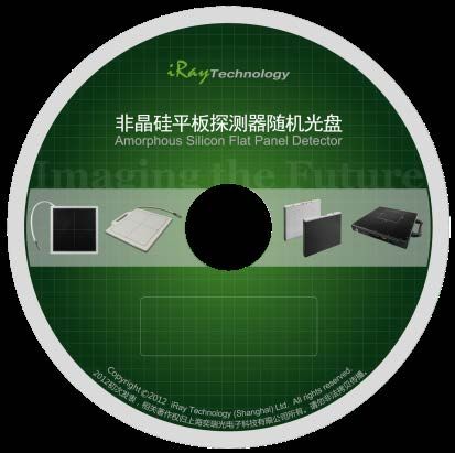
1pcs
Gain correction data
CD-Rom Defect correction map
SDK
Manual
User Manual of Venu1012V 21Flat Panel Detector Venu1012V
2.8 Components Description
2.8.1 Detector
Item Description Comment
L Length of Splitter Refer to 2.8.3
W Width of Splitter Refer to 2.8.3
H Height of Splitter Refer to 2.8.3
K Length of the cable ~ 3m
2.8.2 Detector Cable
The detector cable is replaceable and can be replaced if necessary. It is fixed to the
detector by two screws. So a screwdriver shows below or alike is available when needed.
screw hole
22 User Manual of Venu1012V2. General Description
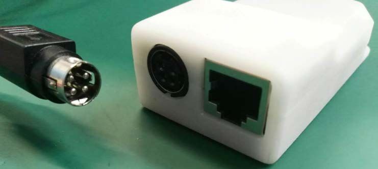
2.8.3 Splitter
The Splitter should be fixed steady.
LAN
Power
Item Dimension (mm) Item Dimension (mm)
A 3 L 92
B 11 W 50
C 23 H 25
D 12
2.8.4 LED Indicator
Once powered on, user can check the status through LED indicator.
STA MOD LIN PWR
Item Description
PWR Power Indicator
LIN Link Indicator
MOD Reserved
User Manual of Venu1012V 23Flat Panel Detector Venu1012V
STA Status Indicator
Power Indicator Lighting Status Description
OFF Power OFF
Green ON Power ON
Link Indicator Lighting Status Description
Power OFF
OFF
No connection
Physical layer connection is
Green ON
established
Status Indicator Lighting Status Description
Power OFF
OFF
Exposure Disable
Green ON Exposure Enable
Orange blinking Safe mode
Orange ON Error
2.8.5 Power Adapter
Item Specification
AC IN 100-240Vac., 50/60Hz 2.5A Max.
DC OUT 24.0Vdc 5.0A
24 User Manual of Venu1012V3. Software Instructions
3 SOFTWARE INSTRUCTIONS
3.1 SYSTEM REQUIREMENT.................................................................................................. 26
3.2 ENVIRONMENT ................................................................................................................ 26
3.3 W IRED CONNECTION ...................................................................................................... 26
3.4 NETWORK CONFIGURATION ........................................................................................... 29
3.5 USER INTERFACE.................................................................................................................. 30
3.6 CALIBRATION ...................................................................................................................... 31
User Manual of Venu1012V 25Flat Panel Detector Venu1012V
3 Software Instructions
Venu1012V provides SDK for user to integrate panel into their DR system. Additionally, it also
provides an application for demonstration, i.e. iDetector. User can use iDetector to control panel
without DR system.
For detailed introduction, please refer to “\Help\Doc”
903-341-13_SDK_ProgrammingGuide
903-341-14_iDetector_UserManual
3.1 System Requirement
iDetector is developed and deployed on Windows Operation System, it can be run on Windows
XP/Windows 7/Windows 8/Windows 10, OS should install latest service pack. The computer
should have at least 4 GB memory. In addition, the firewall should be shut down to avoid
communication issue.
3.2 Environment
Setup files and download url are included in SDK directory: Tools\env_setup
1. Please install Microsoft .NET Framework 4.5(Windows XP only can install V4.0 ). Download
from Microsoft web site, please.
2. Visual C++ redistributed package need to be installed: vcredist_x86_2013(or
vcredist_x64_vs2013).
3. For Windows XP, full path should be used in file “bind.txt”.
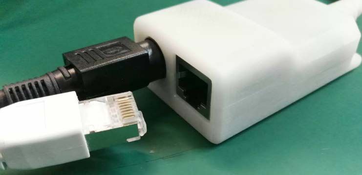
3.3 Wired Connection
Connect the power cable
26 User Manual of Venu1012V3. Software Instructions Connect the Ethernet cable 1. Wait until physical layer connection is established 2. Open local network management interface Double click “TCP/IPv4” User Manual of Venu1012V 27
Flat Panel Detector Venu1012V

1. Enter the IP address and
Subnet mask as follow:
     IP address: 192.168.8.188
     Subnet mask: 255.255.255.0
2. Click “OK”.

1. Open SDK
2. Click “Home”
3. Click “Venu1012V_1”
4. Click “Connect”

28                                User Manual of Venu1012V
3. Software Instructions 3.4 Network Configuration 1. Wait until physical layer connection is established 2. Open local network management interface Double click “TCP/IPv4” User Manual of Venu1012V 29
Flat Panel Detector Venu1012V

1. Enter the IP address and
Subnet mask as follow:
     IP address: 192.168.8.188
     Subnet mask: 255.255.255.0
2. Click “OK”.

5. Open SDK
6. Click “Home”
7. Click “Venu1012V_1”
8. Click “Connect”

3.5 User Interface
SDK supply iDetector as tool software:
32-bits iDetector.exe: Tools\iDetector\w32
64-bits iDetector.exe: Tools\iDetector\x64
Double click iDetector.exe to run the software. For different software version, the UI maybe have
little difference. If change, forgive us for not issuing a separate notice.

30                                                                            User Manual of Venu1012V
3. Software Instructions
Tab Function description
Tab Function description
Home Connect FPD and view the connect state
Acquire Acquire image, select correction mode, save image and process
image
SDK config.ini setting, log level setting
Detector Configurate parameters for detector.
Calibrate Generate calibration files and manage the calibration files
Local File Open and view local images.
3.6 Calibration
3.6.1 Generate Gain Template
1. Select HWPostOffset option on “Acquire” page. Otherwise, the generated gain template
maybe not good.
2. The FDD (Focus to Detector Distance) should be higher than 1.2m. Ensure the whole
active area is covered by the X-ray beam and no objects between the X-ray source and
Detector.
User Manual of Venu1012V 31Flat Panel Detector Venu1012V
3. Click arrow icon to enter Gain Calibration Interface.
4. Click “PREP” button.
5. Exposure and acquire images. If gray value of the image does not meet the
requirement, the mAs of X-ray generator need to be adjusted. A green tips box will be
displayed if the gray value is acceptable.
32 User Manual of Venu1012V3. Software Instructions
6. Repeat step 4, step 5 until all images are captured.
7. Generating Gain template file.
Note:
1. In order to achieve better performance, new gain template should be used when
the kV of the X-ray generator is changed.
2. In order to achieve better performance, new gain template should be used when
the position of the detector is changed.
3. In order to achieve better performance, new gain template should be used when
the FDD is changed.
3.6.2 Download Gain Template
1. Click “Gain”, then Click “DownloadFile” button.
User Manual of Venu1012V 33Flat Panel Detector Venu1012V 2. Click “...” to choose the path. 3. Select the “.gn”file and click “Open(O)” button. 4. Input the File Index. For example, input “1”. Click “OK” button until the file is downloaded successfully. 34 User Manual of Venu1012V
3. Software Instructions

5. Click “ReadStatus” button, choose the right index and click “SelectFile” button.

3.6.3 Generate Defect Template

1. Select SWPostOffset option on “Acquire” page.

2. The FDD (Focus to Detector Distance) should be higher than 1.2m. Ensure the whole
active area is covered by the X-ray beam and no objects between the X-ray source and
Detector.

3. Click arrow icon to enter Defect Calibration Interface.

User Manual of Venu1012V                                                               35
Flat Panel Detector Venu1012V

     4. Click “PREP” button.

     5. Exposure and acquire images. If gray value of image does not meet the requirement,
     the mAs of X-ray generator need to be adjusted. A green tips box will be displayed if the
     gray value is acceptable.

     6. Click “Next” button. Repeat step 4, step 5 until all images are captured.
     7. Click “Next” button(on right-top corner of window) to generate defect template file.
     Note: It is no necessary to update the defect template unless new defect point or defect
     line is found.

36                                                                           User Manual of Venu1012V
3. Software Instructions 3.6.4 Download Defect Template It is very similar to the steps about how to download gain template. 1. Click “Defect”, then Click “DownloadFile” button. 2. Select the “.dft” file and click “Open(O)” button. User Manual of Venu1012V 37
Flat Panel Detector Venu1012V

3. Input the File Index. For example, input “1”. Click “OK” button until the file is downloaded
successfully.

4. Click “ReadStatus” button, choose the right index and click “SelectFile” button.

38                                                                        User Manual of Venu1012V
3. Software Instructions

3.6.5 Pre-offset Template Update

     The pre-offset template can’t be updated automatically. And it may effect the uniformity
     of the corrected image when the pre-offset template is invalid. The operator can update
     the template within two steps.
     1. Select “HWPreOffset” in “Acquire” interface.

2.     Click “UpdateHWPreoffset” button and wait until the message box shows “Task
succeed”.

User Manual of Venu1012V                                                                39
Flat Panel Detector Venu1012V
4 OPERATION
4.1 STEPS FOR ACQUIRING IMAGE................................................................................................. 41
4.2 INNER MODE OPERATION............................................................................................... 41
4.3 FREESYNC MODE OPERATION ....................................................................................... 44
4.4 AFTER USE...................................................................................................................... 46
40 User Manual of Venu1012V4. Operation
4 Operation
4.1 Steps for acquiring image
Make sure the hardware is connected correctly and then power on.
Once powered off, please wait at least 60s before power on again
Wait until initialization is complete
Connect the software
choose the synchronization mode
Generate HWPreOffset, Gain and Defect template after the detector reaches
thermal equilibrium
Acquire images in the selected mode
To Acquire X-ray image is the main operation of Venu1012V. Most importantly,
detector should build synchronization with X-ray generator. Venu1012V has Inner
mode and FreeSync mode.
4.2 Inner Mode Operation
Workstation is a host PC device installed with iDetector and SDK. In Inner mode,
workstation does not control x ray generator. The operator should complete the exposure
within “Exposure Window Time”.
4.2.1 Parameters Setting
When connected, parameters can be set through “Detector” interface. Please DO NOT
change the parameters casually. Incorrect parameters may lead to bad image quality or not
work properly.
Item Description Default
Exposure window. For Inner mode,
exposure need be completed in
Exp Window Time 5000(ms)
exposure window. Otherwise, image will
loss dose.
The time span between the end of
Acquire Delay Time 10(ms)
exposure and the start of acquisition.
Exp Window Time(ms): t5-t1. The time span that detector can accept X-ray, can be set
from 1000ms to 5000ms.
User Manual of Venu1012V 41Flat Panel Detector Venu1012V
Acquire Delay Time(ms): t4-t3. The time span between the end of exposure and the start of
acquisition.
Actual Exposure Time
Actual Exposure Window
Setting Exp Window Time
4.2.2 Work Flow
When connected, select “HWPostOffset”, “HWGain” and “HWDefect”. Then image can be
acquired by clicking “Acquire” button.
Click “Acquire”button
Wait until the warning message change from
“Exposure Prohibit”to “Exposure Enable”
Shoot X- Ray in exposure window once X-Ray
generator is ready
The FPD will acquire image automatically when
detects the end of exposure
Wait until image transfer is complete
42 User Manual of Venu1012V4. Operation
4.2.3 Timing Setting
Process Clear Exposure Acquisition
Detector
2 3 9 10
Workstation
1 4 11 12
Xray Anode X ray Exposure
Generator
Exposure
Prohibited
5 Rotate 6 Exposure Enable 7 shooting 8 Prohibited
1. Workstation receives “Acquire” request and sends “Clear” to the panel.
2. Panel receives “clear” from Workstation, start clear operation. Meanwhile, panel would
send “Exposure Prohibited” to Workstation.
3. Panel finishes ”Clear” operation and send “Exposure Enable” to Workstation.
4. Workstation shows “Exposure Enable” on the iDetector’s message bar to tell user shoot
X ray.
5. User triggers x ray generator to initialize and do anode rotation to prepare for X ray
shooting
6. X-ray generator finishes preparation and reminds users.
7. X ray generator begins releasing x ray
8. X ray generator finishes x ray shooting.
9. X ray sensor in panel triggers panel to start image acquisition operation.
10. Panel completes image acquisition and begins to send data to Workstation.
11. Workstation starts receiving image data from panel.
12. Workstation receives preview image data from panel and display the preview image.
If Hardware Pre-offset and Hardware calibration is selected, image got is the final image.
If Software Pre-offet and Software Calibration is selected, image got would be raw image,
Workstation would finish image processing and image is shown on screen.
If Hardware Post offset and Hardware calibration is selected, image got from panel will be
preview image . After step12, panel would do another dark image acquisition. With both
light and dark image, panel completes correction and calibration process. Finally, panel
uploads processed image to Workstation and image is shown on screen.
User Manual of Venu1012V 43Flat Panel Detector Venu1012V
If Software Post offset and Software calibration is selected, image got from panel would be
preview image. After step12, Workstation sends another “clear Acquire” to panel , panel
would do dark image acquisition and uploads dark image to Workstation. With both light
and dark image, Workstation completes correction and calibration process. Finally,
processed image is shown on screen.
Hardware post offset, hardware gain and hardware defect should be selected in normal
operation .
However, software post offset should be selected when generate the defect template.
4.2.4 Abnormal Action
Action1: after Step4, if user wants to cancel X ray exposure cycle, iDetector provides an
“Abort Exp” function to close exposure window.
Action2: after Step4, if user does not shoot x ray until the exposure window time is run out,
panel would close exposure window automatically and send a message to Workstation that
waiting for X ray shooting is overtime. Meanwhile, panel would also start image acquisition.
After acquisition, panel sends image to Workstation.
4.3 Freesync Mode Operation
Workstation is a host PC device installed with iDetector and SDK. In Freesync mode,
workstation does not control x ray generator. The FPD will detect the start of X-Ray and
acquire the image automatically.
4.3.1 Parameters Setting
When connected, parameters can be set through “Detector” interface. Please DO NOT
change the parameters casually. Incorrect parameters may lead to bad image quality or not
work properly.
Item Description Default
When X-Ray is detected, the detector
Set Delay Time will start to acquire image after Set 1000(ms)
Delay Time.
Set Delay Time: Can be set to 1000 and 2000.
44 User Manual of Venu1012V4. Operation
XRay
Set Delay
Time
4.3.2 Work Flow
When connected, select “HWPostOffset”, “HWGain” and “HWDefect”. Once X-Ray is
detected, the FPD will acquire the image automatically.
Check SDK to make sure panel is ready
Shoot X-ray
X-ray sensor in panel triggers panel to stop flushing
After fixed time, panel starts image acquisition
Wait for image uploaded
4.3.3 Timing Setting
Workstation 2
3 4 5
Panel
1
X ray X
Anode Rotate
Generator Ray
1. X-ray generator is ready for X-ray shooting and begins to release X-ray.
2. Workstation receives “Exposure Prohibited” from Panel.
3. Panel starts uploading preview image to Workstation. If hardware offset is selected,
panel would do offset first, and then upload preview image (2X2 binning).
4. Panel starts uploading Post-dark image to Workstation. If hardware offset is chosen,
panel would do correction and calibration first, then upload processed image to Workstation.
5. Workstation receives “Exposure Enable” from Panel.
User Manual of Venu1012V 45Flat Panel Detector Venu1012V
4.4 After use
Disconnect the software
Power off
Keep it clean
Store under specified conditions
46 User Manual of Venu1012V5. Regulatory Information
5 REGULATORY INFORMATION
5.1 MEDICAL EQUIPMENT SAFETY STANDARDS .................................................................... 48
5.2 GUIDANCE AND MANUFACTURE’S DECLARATION FOR EMC ......................................... 49
5.3 PRODUCT LABEL............................................................................................................. 52
User Manual of Venu1012V 47Flat Panel Detector Venu1012V
5 Regulatory Information
5.1 Medical equipment safety standards
Medical equipment classification
Type of protection against External electrical power source equipment
electrical shock Class I Equipment
Degree of protection against
No Applied Parts.
electrical shock
Degree of protection against
IPX0
ingress of water
Mode of operation Continuous operation
Flammable anesthetics Not suitable for use in the presence of a flammable anesthetic
mixture with air or with oxygen or nitrous oxide
Not suitable for use in the oxygen rich environment
Product safety standards
MDD (93/42/EEC) Medical Device Directive
EN ISO 13485:2012/EN ISO Medical devices --- Quality management systems ---
13485:2012/AC:2012 Requirements for regulatory purposes
EN 60601-1:2006/A1:2013/ Medical electrical equipment -- Part 1: General requirements for
IEC 60601-1:2005/A1:2012 basic safety and essential performance
AAMI / ANSI ES60601- (Consolidated Text) Medical Electrical Equipment - Part 1:
1:2005/(R)2012+A1:2012, General Requirements For Basic Safety And Essential
C1:2009/(R)2012 Performance (Iec 60601-1:2005, Mod).
+A2:2010/(R)2012
Medical electrical equipment - Part 1: General requirements for
CAN/CSA-C22.2 NO. 60601- basic safety and essential performance (Adopted IEC 60601-
1:14 1:2005, third edition, 2005-12, including amendment 1:2012, with
Canadian deviations)
EN 60601-1-2:2015/ Medical electrical equipment – Part 1-2: Collateral standard:
IEC 60601-1-2:2014 Electromagnetic disturbances – Requirements and tests
CAN/CSA-C22.2 NO. 60601- Medical electrical equipment — Part 1-2: General requirements
1-2:16 for basic safety and essential performance — Collateral
48 User Manual of Venu1012V5. Regulatory Information
Standard: Electromagnetic disturbances — Requirements and
tests
EN 60601-2- Medical electrical equipment -- Part 2-54: Particular requirements
54:2009+A1:2015 for the basic safety and essential performance of X ray equipment
/IEC60601-2- for radiography and radioscopy
54:2009+A1:2015
Medical device – Application of risk management to medical
EN ISO 14971:2012
devices
Medical devices - Symbols to be used with medical device labels,
EN ISO 15223-1:2016 /ISO
labelling and information to be supplied - Part 1: General
15223-1:2016
requirements
5.2 Guidance and Manufacture’s Declaration for EMC
EMI & EMS Compliance Table
Table 1 - Emission
Phenomenon Compliance Electromagnetic environment
RF emissions CISPR 11 Professional healthcare facility environment
Group 1, Class B
Harmonic distortion IEC 61000-3-2 Professional healthcare facility environment
Class B
Voltage fluctuations IEC 61000-3-3 Professional healthcare facility environment
and flicker Compliance
EMS Compliance Table
Table 2 - Enclosure Port
Phenomenon Basic EMC Immunity test levels
standard Professional healthcare facility environment
Electrostatic IEC 61000-4-2 ±8 kV contact
Discharge ±2kV, ±4kV, ±8kV, ±15kV air
Radiated RF EM IEC 61000-4-3 3V/m
field 80MHz-2.7GHz
80% AM at 1kHz
Proximity fields from IEC 61000-4-3 Refer to table 3
RF wireless
communications
User Manual of Venu1012V 49Flat Panel Detector Venu1012V
equipment
Rated power IEC 61000-4-8 30A/m
frequency magnetic 50Hz or 60Hz
fields
Table 3 – Proximity fields from RF wireless communications equipment
Test frequency Band Immunity test levels
(MHz) (MHz) Professional healthcare facility environment
385 380-390 Pulse modulation 18Hz, 27V/m
450 430-470 FM, ±5kHz deviation, 1kHz sine, 28V/m
710 704-787 Pulse modulation 217Hz, 9V/m
745
780
810 800-960 Pulse modulation 18Hz, 28V/m
870
930
1720 1700-1990 Pulse modulation 217Hz, 28V/m
1845
1970
2450 2400-2570 Pulse modulation 217Hz, 28V/m
5240 5100-5800 Pulse modulation 217Hz, 9V/m
5500
5785
Table 4 – Input a.c. power Port
Phenomenon Basic EMC Immunity test levels
standard Professional healthcare facility environment
Electrical fast IEC 61000-4-4 ±2 kV
transients/burst 100kHz repetition frequency
Surges IEC 61000-4-5 ±0.5 kV, ±1 kV
Line-to-line
Surges IEC 61000-4-5 ±0.5 kV, ±1 kV, ±2 kV
Line-to-ground
Conducted IEC 61000-4-6 3V, 0.15MHz-80MHz
disturbances 6V in ISM bands between 0.15MHz and 80MHz
induced by RF fields 80%AM at 1kHz
Voltage dips IEC 61000-4-11 0% UT; 0.5 cycle
At 0º, 45º, 90º, 135º, 180º, 225º, 270º and 315º
50 User Manual of Venu1012V5. Regulatory Information
0% UT; 1 cycle
and
70% UT; 25/30 cycles
Single phase: at 0º
Voltage IEC 61000-4-11 0% UT; 250/300 cycles
interruptions
* Professional healthcare facility environment.
* A description of what the OPERATOR can expect if the ESSENTIAL PERFORMANCE is
lost or degraded due to EM DISTURBANCES
* WARNING: Use of this equipment adjacent to or stacked with other equipment should be
avoided because it could result in improper operation.
* A list of all cables and maximum lengths of cables (if applicable), transducers and other
ACCESSORIES that are replaceable.
Name Length Shielding or not Quantity Classify
AC Power Cable 1.8m No shielding 1 AC Power
Ethernet Cable 15m Shielding 1 Signal
* WARNING: Use of accessories, transducers and cables other than those specified or
provided by the manufacturer of this equipment could result in increased electromagnetic
emissions or decreased electromagnetic immunity of this equipment and result in improper
operation.
* WARNING: Portable RF communications equipment (including peripherals such as
antenna cables and external antennas) should be used no closer than 30 cm (12 inches) to
any part of the Venu012V, including cables specified by the manufacturer. Otherwise,
degradation of the performance of this equipment could result.
User Manual of Venu1012V 51Flat Panel Detector Venu1012V 5.3 Product Label 52 User Manual of Venu1012V
6. Service Information

6 SERVICE INFORMATION

         6.1    PRODUCT LIFETIME ........................................................................................................ 54
         6.2    REGULAR INSPECTION AND MAINTENANCE ................................................................... 54
         6.3    REPAIR............................................................................................................................ 54

User Manual of Venu1012V                                                                                                                 53
Flat Panel Detector Venu1012V 6 Service Information 6.1 Product Lifetime The estimated product lifetime is up to 7 years under appropriate regular inspection and maintenance. 6.2 Regular Inspection and Maintenance In order to ensure the safety of patients and operator, maintain the performance and reliability of the panel, be sure to perform regular inspection at least once a year. If necessary, clean up the panel, make adjustments or replace consumables such as fuses etc. There may be cases where overhaul is recommended depending on conditions. Contact iRay service office or local iRay dealer for regular inspection or maintenance. 6.3 Repair If problem cannot be solved even taking the measures indicated in troubleshooting, contact your sales representative or local iRay dealer for repairs. Please refer to the label and provide the following information: Product Name: Series Number: Description of Problem: as clearly as possible. 54 User Manual of Venu1012V
Appendix

APPENDIX
APPENDIX ......................................................................................................................................... 56

 User Manual of Venu1012V                                                                                                                 55
Flat Panel Detector Venu1012V

Appendix A Information of Manufactures

             Company: iRay Korea Limited

             ADDRESS: 1833, 18F, 5, Gasan digital 1-ro, Geumcheon-gu, Seoul, Republic of Korea
             08594

56                                                                       User Manual of Venu1012V
You can also read