Water Rockets A guide to building and understanding the physics of
←
→
Page content transcription
If your browser does not render page correctly, please read the page content below
A guide to building and
understanding the physics of
Water Rockets
Version 1.02
June 2007

Warning:
Water Rocketeering is a potentially dangerous activity and individuals following
the instructions herein do so at their own risk.

Exclusion of liability:
NPL Management Limited cannot exclude the risk of accident and, for this
reason, hereby exclude, to the maximum extent permissible by law, any and all
liability for loss, damage, or harm, howsoever arising.
Contents

WATER ROCKETS

SECTION 1: WHAT IS A WATER ROCKET?                                                   1
SECTION 3: LAUNCHERS                                                                 9
SECTION 4: OPTIMISING ROCKET DESIGN                                                 15
SECTION 5: TESTING YOUR ROCKET                                                      24
SECTION 6: PHYSICS OF A WATER ROCKET                                                29
SECTION 7: COMPUTER SIMULATION                                                      32
SECTION 8: SAFETY                                                                   37
SECTION 9: USEFUL INFORMATION                                                       38
SECTION 10: SOME INTERESTING DETAILS                                                40

Copyright and Reproduction
Michael de Podesta hereby asserts his right to be identified as author of this booklet.
The copyright of this booklet is owned by NPL. Michael de Podesta and NPL grant
permission to reproduce the booklet in part or in whole for any not-for-profit
educational activity, but you must acknowledge both the author and the copyright
owner.

Acknowledgements
I began writing this guide to support people entering the NPL Water Rocket
Competition. So the first acknowledgement has to be to Dr. Nick McCormick, who
founded the competition many years ago and who is still the driving force behind the
activity at NPL. Nick’s instinct for physics and fun has brought pleasure to thousands.

The inspiration to actually begin writing this document instead of just saying that
someone ought to do it, was provided by Andrew Hanson. Once I began writing, lots
of people assisted me, many from the NPL Water Rocket Helpers Team, but I would
particularly like to thank, Dave Lowe, Jaco Stander and Gergely Vargha for advice
about building launchers, permission to use photographs of their equipment, and for
generally putting me right on one or two finer points of rocket design.

Finally, the Water Rocket activity is supported by NPL’s management, and I am
grateful to both the organisation, and many individuals within them. Their support
for this kind of activity is one of the reasons that NPL is such a great place to work.

Thanks to all of you

Michael de Podesta

April 2006
Section 1: What is a water rocket?
At its simplest, a water rocket is
basically an upside down fizzy
drinks bottle, which has had a
‘nose’ cone and some fins added.

The nose cone
The job of the nose cone is to
make the rather snub-nosed end of
the fizzy drinks bottle more
aerodynamic. Also if you have
‘payload’ on your rocket, or a
parachute mechanism, this is
probably where it will be placed.

The fins
Others might disagree, but I think
the fins are the parts of a rocket
that really give a rocket its
character. Technically, the fins are
important for ensuring that the
rocket flies smoothly

Once we have added the fins and
the nose cone, we have something
which looks like a rocket. But how
do we make it go like a rocket?

First we need to add some water,
and some kind of release
mechanism, that will keep the
water in the bottle, until we
choose to release it. The water will
then leave the bottle through its
nozzle.

Typically the bottle will be
between about one quarter and one
third filled with water.

Launch
To launch the water rocket, we need to pump air into the rocket: this provides the
energy for the launch. As the air enters, it bubbles up through the water and
pressurises the ‘empty’ space above the water. You can see that the release
mechanism has to be really quite clever, allowing air into the rocket, while not
allowing the water to escape until we activate a trigger.

                                        1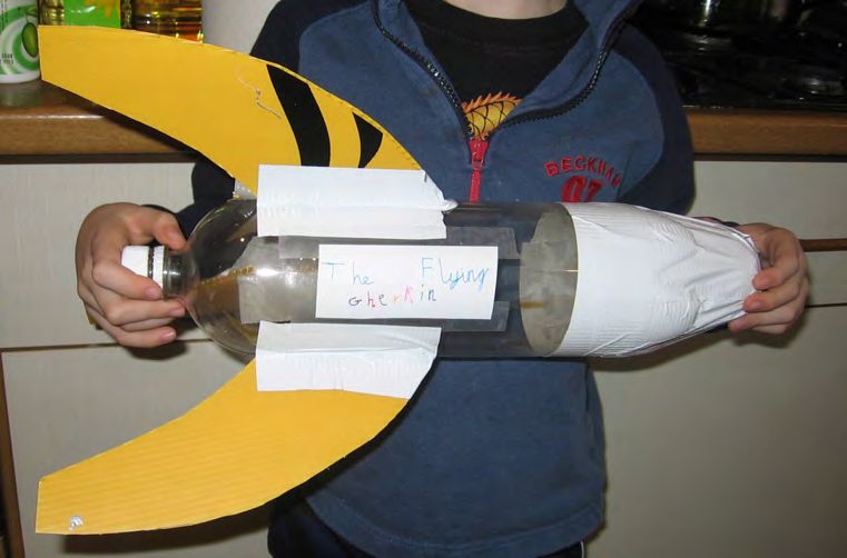
When the trigger activates the release mechanism, the pressurised air within the
rocket pushes the water rapidly out through the nozzle, sending the rocket rapidly into
the air.

Peak launch velocities can easily reach 30 metres per seconds (about 60 miles per
hour), and without too much difficulty its possible for a rocket to reach heights in
excess of 30 m. But launching a rocket straight up in the air can be dangerous…

                                          2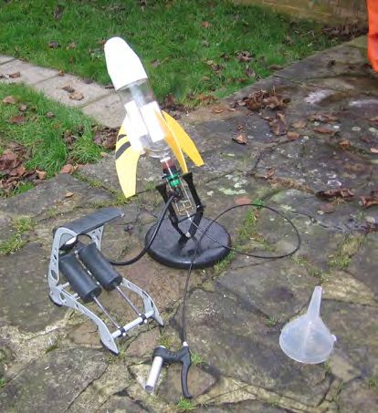
There are two ways to
                              make your water rocket
                              launch safe.

                              The first way is to use a
                              parachute or other similar
                              device to slow the
                              descent of the rocket.
                              Seeing a rocket launch,
                              reach its peak, deploy a
                              parachute and descend
                              gracefully to Earth, is a
                              really great sight.

                              Unfortunately, its not a
                              very common sight,
                              because     getting     a
                              parachute to open at just
                              the right time is very
                              tricky, and requires real
                              ingenuity.

                             The second way to safely
                             launch your water rocket
                             is to launch it an angle.
                             Of course, this makes it
                             safe    for    you,     but
                             potentially dangerous for
                             passers by!
One of the best features about launching at angle is that water rockets can travel really
impressive distances. Reaching 30 or 40 metres should be quite achievable, but
distances beyond 100 m are possible with some careful design.

The main problem with launching the rocket at an angle is that the rocket can no
longer stand on its own feet, and if it is supported entirely by its nozzle, then it tends
to flop over. This happens before launch, and most importantly, it happens just after
launch before the rocket has begun to move quickly.

                                            3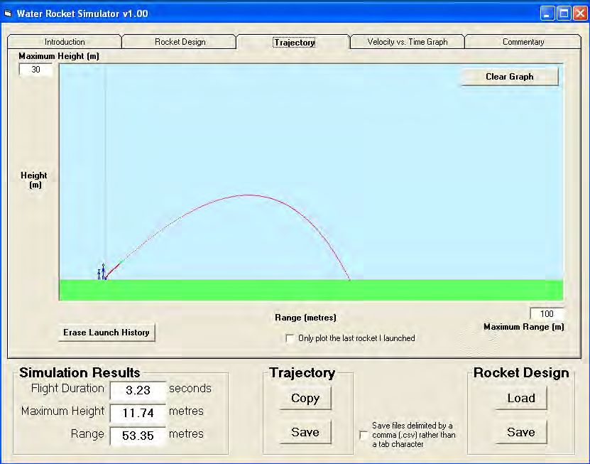
There are two standard ways to solve this problem: launch ramp and launch tubes.

Launch Ramps
A launch ramp supports the weight of the rocket before launch and just after launch,
until its speed has built up.

Launch Tubes
A launch tube is a tube that runs through the nozzle of the rocket. When the trigger
activates the release mechanism, the rocket slides along the launch tube before fully
attaining ‘free flight’. This has two advantages. The first and most obvious advantage
is that the launch tube stops the rocket from ‘flopping over’ just after launch. In this
respect it acts like a kind of ‘internal launch ramp’. The second advantage is not quite
so obvious. Once the trigger has been activated, the high pressure gas inside the
rocket expands, and pushes (as the middle section of the figure below shows) the
rocket along the launch tube. As it slides along the launch tube it accelerates, and it
can be moving quite fast when it leaves the launch tube. However, while it is on the
launch tube, it is not losing any water. This gives the rocket a kind of ‘moving start’
and allows it to use its charge of water more effectively. This can significantly
improve its performance.

                                           4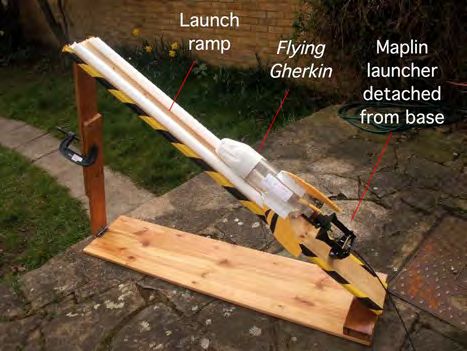
Why?
So now you know what a water rocket is. But perhaps the question still lingers:
What’s the point? The answer is very simple: building and launching rockets is just
enormously enjoyable. It combines the simple pleasure of watching in awe at the
power of a compressed gas, with the rather more subtle pleasure of mastering an
engineering problem. In short, its fun for all ages.
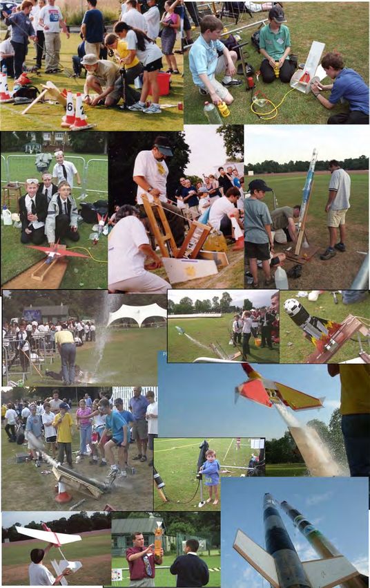
The challenge: Some teams, designs and launches from NPL’s Water Rocket Challenge
Photo Credits: Photos from the NPL Water Rocket Challenge Web Site. Thanks to Mike Parfitt, Steve Forrester, Clive Scoggins, Stuart Rogers
5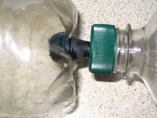
Section 2: How to make a basic water rocket

In Section 1, we saw what a water rocket was. In this section we’ll see in detail how
to make a basic water rocket that will fly pretty well in a wide range of conditions.
We’ll cover how to launch your rocket in Section 3.

2.1 A Basic Rocket

What you will need
  • A two-litre fizzy drinks bottle: this will form the main body of the rocket. Be
      sure only to use bottles that contained fizzy drinks: similar looking bottles
      which contained still drinks (cordial, milk drinks etc.) are not suitable. Fzzy
      drinks bottles are made from PET (short for Polyethylene Terephthalate), an
      enormously strong plastic.
  • A tennis ball, or rubber ball weighing about 60 g. This will form the main part
      of the nose.
  • Some corrugated cardboard, or better still, corrugated plastic. This will be
      used to make the fins.
  • ‘Duck’ tape or equivalent strong, sticky tape.
  • Scissors or a knife.
  • Time: Between 30 and 40 minutes

When completed it will look like…

Schematic                                     Actual

First of all…
…you start with a fizzy drinks bottle. You need to
empty out the fizzy drink, get rid of the labels, and
rinse it with water. Supermarkets sell ‘value’ ranges
of lemonade and fizzy water that cost only perhaps
20 pence per bottle so this shouldn’t cost too much.

Now you need to add a nose cone and some fins

                                          6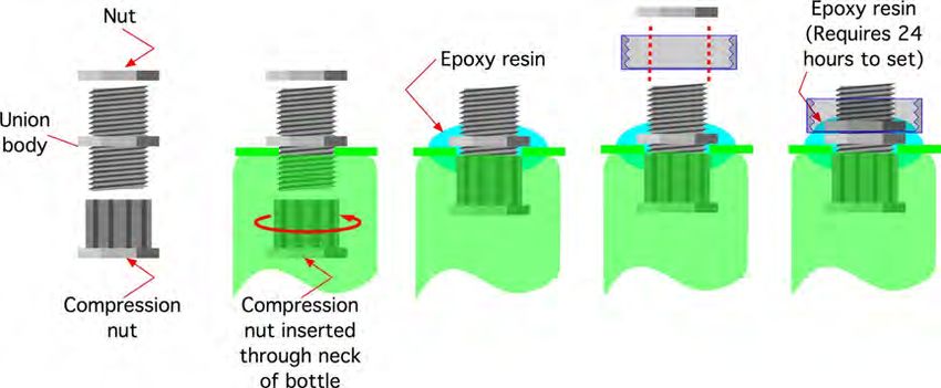
The nose cone
                      The nose cone needs to be slightly pointed, and
                      as we’ll see in Section 4, it’s also important to
                      have a little bit of weight towards the front of the
                      rocket.

                      My favourite way of achieving both these aims
                      is simply to tape a tennis ball to the end of the
                      bottle.

                      This might not look quite as aerodynamic as you
                      were hoping for, but trust me, it will fly!

The fins
These fins were cut out of an old
estate agent’s ‘For Sale’ board.
More         technically,     this
corrugated plastic (known as
Corriflute™) is waterproof, and
has excellent rigidity for its
weight. If you can’t find any old
‘For Sale’ signs, a source of
Corriflute is listed in Section 9.
However, then there are many
suitable alternatives.
Corrugated cardboard will do, but does tend to go soggy after a few launches. Also
many packaging materials have the same design requirements as water rocket fins
(high rigidity-to-weight ratio). One common choice is to cut up old CD’s to use as
fins. If you do this please then make sure you put tape over any sharp edges in case
your rocket should hit someone.
I’ve used three fins rather than four, because three fins means one less fin to cut out!
I’ve included a picture showing the actual dimensions I used on these fins, but this
design is far from optimal. I like this design because the rocket can stand on the fins

                                           7
(which is actually quite handy), and they make the rocket look a little bit like the
rockets from Tintin books.
The fins are simply taped to the side of the rocket. They need to be reasonably firmly
attached in order to stop them being ripped off during the launch. The fins will almost
certainly be damaged on landing, but then they will not be too difficult to repair.
Whether you use this fin design or your own, the important things about the fins are
that:
• All the fins should be the same as each other,
• They should be positioned towards the back of the rocket.
• They should arranged symmetrically around the rocket (every 120° if you
have three fins or every 90° if you have four)
• They should be thin when viewed ‘head on’
Decoration
Decorating and naming your rocket can give a disproportionate amount of pleasure
for the time it takes: I give you: The Flying Gherkin!
Critique
This rocket is not optimised in many ways, and in Section 4 we’ll see how to optimise
each part of the rocket, and discuss the different design compromises that you will
need to make. But you can probably already see that it could be made lighter, the nose
cone could be made more aerodynamic, and the fins could be reduced in size.
However, the aerodynamics are not too bad, and the weight and fin size are such as to
keep the rocket stable in flight. In short: it’s not a bad starting point.
Vital Statistics
Internal Volume 2 litres
Mass when empty 171 g (0.171 kg)
Length 45 cm (0.45 m)
Area of Fins 1200 cm2
Frontal Cross Sectional area 62 cm2
8Section 3: Launchers
Launchers are more complicated to build than rockets, and it will take you much
longer to build a launcher than it will to build a rocket. For this reason I think you
might like to consider investing in a commercial launcher. I tested the rocket
described in the previous section using a launch system available from Maplin
(Section 9).
The Maplin system uses a special nozzle which screws onto the bottle in place of its
cap. The nozzle is shaped to fit into normal garden hose fittings, and the system
comes with a quick release based on normal garden hose connectors, and activated by
a neat system based on a bicycle brake cable mechanism.
Right: details of
the special
nozzles used by
the Maplin
Launcher
Far Right: The
nozzle screwed
onto the rocket.
Right: The rocket
The Flying
Gherkin installed
on the Maplin
Launcher ready
for launch
Far Right: Filling
the rocket with a
measured charge
of water.
Personally, I have used parts of the
Maplin launcher mechanism, but
attached them to my own launch
ramp. It’s not the best design in the
world, but it is my design.
And it may be that you too long to
design and build your own launcher.
In which case, the following pages
may be of assistance.
9Making your own launcher
First of all, a confession: before I made the launcher shown on the previous page, I
made a launcher similar to those featured below. However it didn’t work very well.
So these instructions are not based on what I have done, but rather on what I would
have done if I had been clever enough to consult my colleagues before I started
building. Launchers are more complicated than water rockets, and if you are
attempting this, then you are probably quite good at DIY, and won’t need complete
instructions. So in this section I will only describe those parts that I think are not
obvious. I will describe two designs, one without a launch tube (Design A) and one
with a launch tube (Design B). If you attend any water rocket gathering, you will see
that these designs are simply two stars in a galaxy of possible designs.
When completed your launcher might look something like…
Below: Schematic of the main components of a launcher.
Below Left : A typical rocket launcher without a Below Right : A typical rocket launcher with a launch
launch tube: we’ll call this Design A. tube: we’ll call this Design B.
10The launching Mechanism
Connecting the rocket to the launcher and designing a launching mechanism is
probably the trickiest part of the construction. Let’s look at how the two designs
approach this.
Design A
Design A is Jaco Stander's version of the Ian Clark’s cable tie launcher (see Section 9
for a web link), and is constructed out of standard 15 mm copper plumbing tube
soldered together. Soldering is probably quite hard for beginners, so as an alternative,
the launcher could have been made using either compression fittings (which can be
made pressure tight with spanners) or ‘push fit’ fittings (which require no additional
tools). However, the design depends on small details of the fittings so you will need to
check what will and won’t work with the particular fittings you choose.
In this design, the screw thread on the outer Before Sanding After Sanding
part of the bottle is removed with sand paper
to make a smooth surface. This can be done
by hand, but a much better finish can be
achieved by spinning the bottle and applying
gentle pressure with sand paper.
The launcher and launching procedure is illustrated in the Figure below.
The launching technique for Design A (a) The bottle fits into a 28 mm to 28 mm ‘straight through’
connector, attached to a 28 mm to 15 mm reducing adapter, which in turn is attached to 15 mm
copper pipe. (b) The modified bottle-end is fitted snugly into the 28 mm throat of the adapter. The
pressurised seal is achieved by the use of a thin 28 mm diameter ‘O’ ring. Notice that at this point all
the pipework visible in the illustration will be filled with water. (c) The bottle is then locked in place by
cable ties, which in turn are held in place by large diameter plastic plumbing tube. At this point the
rocket can be pressurised, and will not launch until (d) the large diameter plumbing tube is pulled
away. This allows the cable ties to move outwards permitting the rocket to launch.
(a) (b) (c) (d)
The major problem with Design A is that the rocket is only supported at the neck, and
since a large rocket can weigh several kilograms when filled with water, this makes
the rocket liable to ‘sag’ before launch. This could be overcome by the addition of
either a launch ramp to support the rocket, or a launch tube. A photograph of the
launcher in action can be seen in the collection on Page 5 (one down from the top
right), where Jaco has used an improvised launch ramp.
11Design B
Design B is by Dave Lowe, and uses a launch tube to add support and give extra
momentum at launch. It is constructed out of two types of plumping pipe: standard
22 mm diameter plastic plumbing tube, and undersized 21.5 mm plastic ‘overflow’
pipe. It is assembled using simple push-fit plumbing connections.
In this design, a 22 mm diameter hole is drilled
through a standard bottle cap. Be careful when drilling
because any drilling operation could be hazardous!
The plastic of the cap is soft, and we recommend the
use of wood bit rather than a conventional high-speed
steel drill. The cap can now be slipped over the
21.5 mm overflow pipe trapping an ‘O’ ring between
the bottle top and the tube. This should form a
pressure-tight sliding seal against the wall of the tube.
• Standard 22 mm plumbing tube will not fit inside
the neck of PET bottle. To make sure you get the
correct type of pipe, take a bottle along to the shop
to check the pipe will fit before you buy it!
• If the bottle is a tight fit on the tube, reduce its
diameter slightly using sandpaper. One technique
is to fit the tube into a drill and rotate it, and hold
fine sand paper against the tube.
• You may need to add a small amount of
lubricating oil or grease to allow the bottle to slide
easily along the tube.
The launching technique for Design B (a) The bottle with its modified cap slips over a piece of
polished 22 mm plastic pipe. In this design, the pipework visible in the illustration extends far enough
into the bottle to prevent water overflowing into the pipes. (b) The bottle is then locked in place by
cable ties, which in turn (c) are held in place by large diameter plastic plumbing tube. At this point the
rocket can be pressurised, and will not launch until (d) the large diameter plumbing tube is pulled away.
This allows the cable ties to move outwards permitting the rocket to launch.
(a) (b) (c) (d)
12Designs A and B both use cable ties as a key component in the launching mechanism,
but as the photographs below show, they adopt a what I can only describe as different
design philosophies. Dave has gone for the minimum of three cable ties, and Jaco has
gone for the maximum number of cable ties that can be arranged around the rim of the
bottle. Which is better? I don’t know: they both work very reliably!
Photographs of Designs A and Design B
Details of the launch mechanism of Design A. Below.
The cable ties loosely arranged around the 28 mm to 15
mm plumbing adapter. Right. The large diameter
plumbing tube has been lifted up to clamp the cable ties
over the neck of the rocket.
Details of the launch mechanism of Design B.
Right. The arrangement of the bottle, the sealing
‘O’ ring and the modified cap used to clamp the ‘O’
ring against the launch tube.
Far Right. The three cable ties held loosely
arranged around the neck of a bottle. The large
diameter plumbing tube has not been lifted up
completely to clamp the cable ties over the neck of
the rocket. Notice that launch tube continues inside
the water rocket
2. Pressurised connections & the pumping valve
Both designs A and B use pipework systems that are readily available from plumber’s
merchants and DIY stores. However one part of a rocket launcher which is not
available from shops is a component to allow connection between these pipework
systems and a bicycle pump. Both designs tackle this by installing either a bicycle
tyre valve or a car tyre valve. The Figure over the page shows details of Design A’s
connector.
13Details of the pumping valve in Design A. Left. The valve is shown disassembled, showing (from left
to right) a standard 15 mm compression fitting (called a ‘union’); a car tyre valve; the compression nut.
Right. The valve shown assembled.
A similar arrangement can be made with 22 mm
plumbing fittings, but there it will be necessary to drill
a hole in an end-cap, and to fit the car tyre valve in
place. Glue or sealant should not be necessary, because
the tyre valve fitting is designed so that as the pressure
increases, the seal will improve. A similar design can
also be made using bicycle tyre valves
Pump types
One last feature of launcher design concerns the choice of pump used to pressurise the
water rocket. There are broadly three types of pumps available: Hand pumps, foot
pumps, and stirrup pumps. Any of these can be used, but the ‘must have’ feature for
any pump you choose is a pressure gauge: if the pump doesn’t have a pressure gauge
then you will have no idea how your rocket will perform and be unable get it to
behave reproducibly.
Having said that any type of pump can be used, I would definitely not recommend a
normal bicycle hand pump. The amazing performance of water rockets comes from
energy stored in the compressed air, and the source of the work required to compress
the air is your arms and legs. Aside, from normally lacking a pressure gauge, hand-
powered pumps are very hard work. Stirrup pumps (which allow the work to be
shared across both arms), and foot pumps (especially dual-piston pumps) are both
popular, but amongst the people who do a lot of rocketeering, the stirrup pump seems
to be the preferred choice.
14Section 4: Optimising Rocket Design
Aside from actually firing the rockets, designing the rocket itself is the part of
rocketeering I enjoy most. In this section we’ll look at some of the factors that you
will need to consider if you want to optimise the design of your rocket.
Design considerations
Size (Volume)
The first consideration is the size of the rocket you want to construct. Looking around
the shops, you will see a wide range of fizzy drinks bottles available, and any of them
can be modified to make a water rocket. It’s common to find 500 ml, 1 litre, 2 litre
and even 3 litre bottles. Larger bottles tend make more spectacular launches, but if
you want to go larger than three litres then you will need to construct a rocket by
joining together more than one bottle. There’s some tips on how to make multi-bottle
rockets later on in this section
The volume of the rocket determines the maximum amount of energy that can be
stored in the compressed gas. The energy is proportional to both the pressure and the
volume. There are limits to the pressure that the rocket can sustain (5 atmospheres [or
75 psi] appears to be a safe working limit) and so in order to increase the total amount
of energy available, it is necessary to use a larger rocket. With a little ingenuity it is
possible to increase the volume with relatively little cost in terms of added weight.
Weight
The lower the weight of your water rocket, the better it will fly. Most of the work of
designing a lightweight rigid structure has been done for you already by the
manufacturers of the fantastically strong PET bottles. In order to capitalise on the
strength-to-weight ratio of the bottles, you need to avoid adding too much weight as
you improve the aerodynamics of the bottle. It is also important to add the weight in
the correct places so that your rocket is aerodynamically stable. The distribution of
weight along the length of the rocket is one of the factors which determines whether it
will fly like rocket, or like a bottle. What’s the difference?
An aerodynamically stable rocket flies with its nose first, and should have a flight
trajectory like a beautiful smooth arc.
Right: An aerodynamically
stable rocket trajectory.
Notice that air-resistance
tends to make the
trajectory asymmetric, with
the rocket falling rather
more steeply than it
ascends.
An aerodynamically unstable rocket may start out with its nose first, but its flight will
quickly become unstable and it will flap and tumble in the air, and then simply fall to
Earth.
15Right: An aerodynamically
un-stable ‘bottle’ trajectory.
Several commercially sold
rocket systems have
rockets that perform in this
way.
In order to make your rocket fly ‘like a rocket’ rather than ‘like a bottle’, the weight
needs to be in the front half of the rocket. However depending on the design of your
fins, this may or may not be enough to ensure aerodynamically stable flight. One of
the most important properties of your rocket is the position of its centre of mass,
sometimes called its centre of gravity.
Estimating the position of the Centre of Mass
Since your rocket will spend most of its flight without any water in it, this makes it
easy to find its the centre of mass by simply tying a string around the rocket and
moving the suspension point along the rocket until you find the balance point. The
further forward this balance point, the more likely it is that your rocket will be stable
in flight.
Below: Finding the centre of mass of a rocket by suspending it from a thread.
Fins
The fins on a rocket provide a mechanism by which aerodynamically stable flight can
be ensured. To understand the role of the fins, it is necessary to consider the forces on
a rocket when it becomes slightly misaligned in flight. If these forces act to increase
the degree of misalignment, then the rocket will not fly well. If these forces act to
decrease the degree of misalignment, then the rocket will fly… like a rocket! We’ll
see how the fins help to achieve stability in the next section.
Aerodynamic stability
To understand aerodynamic stability we need to consider the forces which act on the
rocket both when it is flying correctly, and also when it is misaligned. Let’s consider
two different rockets (let’s call them Rocket A and Rocket B) which are the same
shape and have the same fins, but which have different weight distributions and so
have their centres of mass positioned at different places. In particular let’s assume that
Rocket B has its centre of mass much further back than in Rocket A.
16Rocket A Rocket B
Now let’s think about the forces when the
rocket is travelling in the direction of the
blue arrow.
The main drag forces act on all the
surfaces exposed to air moving past the
rocket. For a typical rocket oriented
‘correctly’, these forces act mainly on the
nose cone, because the fins are usually
very thin and expose very little cross
section to the air through which they
move.
Now consider what would happen if the
rocket became slightly misaligned. In this
case much more of the rocket would be
exposed, and the drag forces would
increase significantly.
The forces would act:
• on the nose of the rocket,
• along the exposed side of the
rocket,
• and on the fins.
The forces along each portion of the
rocket are difficult to calculate or
measure precisely, but there will be some
point on the rocket which is their
effective point of action. This point is
known as the centre of pressure, and is
marked with a purple dot in the figures
right and left.
Because the shapes of the two rockets are
the same, the centre of pressure lies in the
same place. But because the centre of
mass occurs in different places on each
rocket, the effect of the same drag forces
on each rocket is quite different.
17For Rocket A (left) the centre of mass lies
further forwards along the rocket axis
than the centre of pressure. The extra drag
forces therefore act more on the back end
of the rocket and tend to ‘push it back
into line’. Technically we say the drag
forces exert a torque which acts about the
centre of mass to restore optimal flight
attitude.
For Rocket B (right) the centre of mass
lies further backwards along the rocket
axis than the centre of pressure. The extra
drag forces therefore act more on the
front end of the rocket and tend to ‘push it
even further out of line’.
So it is the relative positions of the centre of mass and the centre of pressure that
determines whether a rocket is aerodynamically stable (like Rocket A) or unstable
(like Rocket B). We saw in a previous section how to determine the position of the
centre of mass, but how do we determine the position of the centre of pressure?
Estimating the position of the Centre of Pressure
Estimating the position of the centre of pressure turns out to be rather hard to do
accurately, but there is a simple technique which you can use to make a rough
estimate of its position. This involves making a flat ‘silhouette’ of your rocket. To
understand why this is relevant look at the photographs below which show what the
rocket would like if it became misaligned in flight.
Left: A photograph of the ‘Flying
Gherkin’ from directly above its nose
cone: this is what you would see if the
rocket were flying directly towards
you.
Right: Exposed surfaces of the
rocket: The circle shows the area of
the rocket exposed to the oncoming
air. The fins are rather thin and move
easily through the air.
Left: This picture shows the ‘Flying
Gherkin’ slightly misaligned: this is
what you would see if the rocket were
flying directly towards you, but its
back end had swung around slightly.
Right: In this attitude, additional
surfaces (outlined and shaded) are
exposed to the oncoming air. Some of
these surfaces are on the side of the
rocket and some are on the fins.
18The silhouette technique considers what would happen if for some reason your rocket
were flying through the air sideways. This is obviously a more extreme scenario than
the misalignments considered above, but let’s follow the logic through. If this were
happening then the surfaces of the rocket exposed to oncoming air would not form a
circle (as when the rocket is correctly oriented) but rather would look like a silhouette
of the entire rocket. The position of the centre of pressure of the rocket can be
estimated making a silhouette (or cut out) of the rocket, and then estimating the centre
of mass of the cut-out.
Illustration of the silhouette technique for
estimating the centre of pressure.
Above Left: Drawing around the rocket.
Above Right: Silhouette (cut out)of the rocket .
Right. Assessing the centre of mass of the rocket
and its silhouette together. We estimate the centre
of pressure of the rocket to be in roughly the same
relative position as the centre of mass of the
silhouette. Notice that the rocket design with its
large light, fins projecting back from the body of the
rocket help to keep the centre of pressure towards
the rear of the rocket. Also, extra weight in the
nose of the rocket (a tennis ball) helps to keep
centre of mass towards the front of the rocket.
As the photograph above shows, the centre of mass of the silhouette is much further
back along the rocket body than the centre of mass of the rocket itself. To the extent
that the centre of mass of the silhouette really is a good estimator for the centre of
pressure of the rocket, we can see immediately that The Flying Gherkin is
aerodynamically stable. If the Flying Gherkin were flying sideways, then the air
pressure would cause an effective force to act at the centre of pressure. Since the
centre of pressure lies further back along the rocket than the centre of mass, the air
pressure causes the rear of the rocket to be pushed backwards, and the nose of the
rocket to swing forward, restoring the correct flight attitude.
Tip: If your rocket is bigger than a sheet or two of A4 paper, then rather than drawing
around your rocket, you may find it easier to make a scale drawing of your rocket.
Drag
As the water leaves the rocket’s nozzle, it pushes the rocket forward. But this
acceleration is decreased because the rocket needs to push air out of the way. The
force required to push air out of the way is known as aerodynamic drag, and without
specialist facilities, it is rather difficult to measure.
19Travelling at just a few metres per second we are hardly aware of drag, but at higher
speeds, drag dominates the motion of projectiles. For the rocket-shaped projectiles we
are interested in, drag forces become significant above approximately 10 metres per
second. Just after launch, a water rocket might reach a maximum speed of 20 metres
per second, and a high-pressure rocket might reach 40 metres per second. At speeds
such as this it is essential to create a design with low drag. Assuming your design is
basically rocket shaped (pointy-nose, long body, fins) then you can minimise the drag
by considering the following points.
Nose: This nose needs to be :
• Cone shaped, but there is no need to make it excessively pointy. In fact, from
a safety point of view this is really quite undesirable.
• Weight may need to be placed in the nose. I am fond of using tape around a
tennis ball, but other designs use plasticine stuffed into a cardboard or plastic
nose cone.
Body: The body needs to be:
• As smooth as possible.
• For a given rocket volume, long thin rockets tend to have lower drag than
short fat rockets.
Fins: The fins need to be:
• Thin and light
• Arranged symmetrically around the body of the rocket: usually there are three
or four of them.
• Positioned as far back along the rocket as possible
Fairings
A fairing is defined in my online dictionary as:
fair·ing1 n
a streamlined structure added to an
aircraft, car, or other vehicle to reduce
drag. See also cowling
Fairings are used in two quite different ways. The first
technique is used when joining two bottles together: a mid-
section of a bottle is cut out and placed around the joint for
strength and streamlining (see Figure on page 22). The second
technique (see right) adds whole bottles or parts of bottles onto
the water rocket ‘engine’ to produce a longer rocket. This is a
useful way of moving the centre of mass forward along the
rocket to improve stability.
Nozzle
The nozzle is the ‘transducer’ which converts the energy of the expanding air into
linear momentum of the water exiting the back of the rocket. The efficiency of the
nozzle measures the extent to which energy is wasted in this process. Losses can
occur due to friction, viscosity, and off-axis acceleration of the water. You have rather
little control over the first two of these properties, but your design can affect the third
process.
20Consider the two bottles shown left and right: the left-hand figure
represents the standard fizzy drinks bottle, and gives acceptable
nozzle performance. However, the style of bottle shown right offers
improved nozzle performance. Its gently sloping ‘shoulders’ guide
water in just the right direction and little energy is wasted in
pushing the water ‘sideways’ towards the nozzle. Unfortunately this
style seems to be only available in one litre sizes.
One further parameter may be used to describe a nozzle: its flow impedance. This is
mainly determined by the minimum cross-sectional area: the larger the area, the lower
the impedance, and the quicker water comes out; the smaller the area, the higher the
impedance, and the slower water comes out. In the limiting case of a very high
impedance, water will simply trickle out the bottle, and it will not leave the ground.
Multibottle rockets
Joining two or more bottles together to make a pressure-tight joint is simple in
principle, but tricky in practice. The basic technique is to find a component (typically
a plumbing connector or valve) which will mechanically join the bottles, and then to
seal the component in place. Let’s look at a couple of similar techniques.
In the first technique one begins by drilling a hole in the
centre of the bottom of a bottle. The hole should be around
12.5 mm in diameter (a half-inch drill will be fine). A
wood drill will generally give a better result than a standard
high-speed steel drill.
Now one inserts a car tyre valve into the bottom of the
bottle. This is the same kind of valve that Jaco and Dave
used to make their pumping valve and is illustrated on
Page 14
Before inserting the valve into the bottle, the insides of the
valve need to be removed with needle-nosed pliers or
similar. This should result in a straight hole through the
centre of valve with a diameter of roughly 3 mm.
Now we need to attach another bottle to this valve. To do this we begin with a
standard bottle cap and drill a hole which will allow the stem of the tyre valve to
protrude as shown below. We now have to make the connection pressure tight.
To do this one first places a rubber washer over the valve stem, and squeezes it tightly
into place with a nut made from a cut down cap for a tyre valve. One then seals the
entire connection with silicone sealant and allows the assembly to set for 24 hours.
21The arrangement now looks like
the leftmost figure in the set right.
One can now screw a second
bottle into the first bottle to make
a pressure tight seal. The
resulting joint should be pressure
tight, but it is not very
aerodynamic, and will also be
rather fragile and flexible.
The last step is to add a fairing to
reduce drag. One clever way to
do this is to cut out the central
part of yet another bottle and slip
it over the combined bottles.
To do this you will find it convenient to slightly reduce the pressure in the combined
bottles by sucking on them. The combined bottles will crumple a little, but this does
not seem to affect their strength as long as the plastic is not creased. When re-
inflated, the fairing will be held firmly in place.
This process can then be repeated to make rockets as large as you have the patience to
create. Please note, however, that since the energy stored in a large rocket can be
considerable when pressurised, you should be sure to observe the pressure safety
precautions (Section 8).
Joining bottles together. Left: Bottle cap attached to the bottom of a bottle. Centre: Two bottles joined
together (the fairing is not yet in place) Far Right: There are many other ways of joining bottles together
using cable entry grommets or similar. Small hands are an advantage for this fiddly work.
Alternative technique: Using similar principles to those described above, a cable entry grommet for
electrical wiring (above right) can be used to make a large aperture bottle connector.
22Parachutes
I am not in a position to tell you how to get a parachute to deploy correctly, because I
have never managed to do it myself! Also, when I’ve asked people who have done it
what the secret is, they have been somewhat… secretive! But I can tell you why it is
so difficult, and I can pass on one or two hints given by some of the less secretive
rocketeers.
Generally its considered that the ideal time for deployment is when the rocket reaches
its maximum height (apogee). The problem is to tell when this occurs.
40
The Figure (right) shows Water expelled
the calculated speed of a
standard rocket as a 30 'Gas Blast' ends
function of time. From
this graph it is possible 20
to see why detecting the Horizontal velocity
Velocity (m/s)
apogee is a problem.
After the acceleration 10
phase, both the
horizontal and vertical 0
components of the
rocket velocity gently
-10 When the vertical velocity
decrease. At the apogee,
component is zero the rocket Vertical velocity
there is no change in the is at its maximum height
forces acting on the -20
rocket, and so it is hard 0 0.5 1 1.5 2 2.5 3 3.5
to detect. Time (s)
In order to arrange for the parachute to deploy correctly, I have seen only two generic
types of mechanism. The first detects the height of the rocket, and the second
activates at a pre-determined time. Another possibility would be to have a mechanism
based on the orientation of the rocket, but I have never seen this implemented.
The first height-detecting mechanism I have seen consisted of a piece of thread
attached to the ground: it broke during the rapid acceleration phase.
The second height-detecting mechanism consisted of a rocketeer with a radio-control.
The parachute was stowed in the nose of the rocket beneath a cover which was held in
place by nylon fishing line. The radio control activated a heater that melted the fishing
line, causing elastic bands to pull off the cover, allowing the parachute to deploy. This
ingenious mechanism worked perfectly. Most of the time. This type of deployment
mechanism could also be used with a timer.
The mechanisms based on timing involved a tiny clockwork timer (See Section 9)
which could be set to activate after periods of just a few seconds or so. Arranging for
the timer to be started on launch, and then deploy correctly proved very tricky. When
the mechanism worked, it worked perfectly, but frequently it deployed the parachute
on launch, or failed to deploy it all.
23Section 5: Testing your Rocket
The way you test your rocket is what distinguishes those who want to just have bit of
fun (which is great in itself) and those who want to understand and improve their
design (which the first step on the road to being a successful engineer). At the heart of
this test process is measurement. You need to:
• measure the properties of rocket before launch, and then
• measure the performance of rocket.
You then need to use your understanding of the launch process and flight dynamics to
try to work out which launch properties most significantly affect the performance of
the rocket.
Rocket Properties
Weight of Empty Rocket: This is (pretty obviously) the weight of the rocket without
the water in it. This will be the part of the rocket which makes the whole journey.
Using electronic kitchen scales it is not too difficult to measure to the nearest
gramme, which is more than accurate enough for our purposes.
Total Volume: If you have just a single bottle design, the total volume is likely to be
very close to the volume stated on the label. If you have constructed a multi-bottle
rocket, then you probably need to measure this. The easiest way is to weigh the rocket
empty (see above) and then weigh it full of water. Each gramme of excess weight
corresponds to 1 cubic centimetre of water. Or each kilogramme corresponds to 1 litre
of water.
Water Volume: This is something you can easily customise and which makes a big
difference to the performance. A good starting point is generally to fill with about one
quarter water. The optimum filling depends on a number of factors, but is generally in
the range from 20% to 30%. One thing you can do before you leave home, is to mark
the side of the rocket with tape to show where (say) the 20% or 25% mark is:
remember you will generally be filling the rocket when it is upside down so this mark
will generally be in a non-obvious position.
Launch Angle: If the rocket were an un-powered projectile with no aerodynamic
drag, then the angle to give the greatest range would be 45°. However, this is not the
case for a water rocket, although the optimum angle is unlikely to be very far from
45°. My feeling is that launching slightly more vertically than this gives the best
range, but you should check this for your rocket.
Launch Pressure: Increasing the pressure increases the stored energy at launch,
which increases the maximum speed attained by the rocket, and this increases the
launch range, flight time, and maximum height. However, you will find that
increasing the launch pressure by a given amount (a) becomes harder to do and (b)
makes less and less difference. The reason is aerodynamic drag which increase very
rapidly with increasing launch speed, and ‘steals’ all the kinetic energy imparted to
the rocket. If you have a launch pressure of 5 atmospheres (75 psi) and are still
looking for improvements, then its better to try reducing drag rather than increasing
the pressure further.
Other features: You need to note how you have set the fins, or whether you are
trying any other interesting alterations either to the rocket or to the launcher.
Rocket Performance
Ground Range: This is the distance between the launch point and the point where the
rocket hits the ground. When you begin rocketeering, increasing the range is simplest
24and most obvious measure of success, but as you get better, you will find that
increasing the range is not so obviously a good thing. The first problem is that once
the range becomes long (beyond 100 m or so) it takes a long time to measure the
range and retrieve your rocket. Secondly, depending on the kind of space you have
available to launch into, it becomes increasingly difficult to ensure that your rocket
will not hit a passer by, or leave the field or park where you are practicing. At the
extremes of the range — over 200 m — it simply becomes impossible to find
anywhere to safely launch!
The best way to measure the range is probably with a wheel-based odometer.
However, for most practical purposes, counting an adult’s purposeful strides to the
landing point will suffice for comparative measurement. If you want to go one step
better than this (no pun intended), the adult can calibrate their stride by walking 10
purposeful paces, and measuring the distance travelled. From this you can work out
the actual length of each stride in metres.
Height: This is a really interesting property of the rocket’s trajectory, but
unfortunately one that is very hard to measure. If you really want to know how high
the rocket goes, then I would recommend a straight up launch (see Page 3 for
warning!) with a long length of sewing thread attached to the tail of the rocket. The
thread should be laid out on the ground, so that as the rocket increases in altitude it
can lift the thread off the ground. If you want to measure the height for a non-vertical
launch, then (aside from complicated triangulation from analysis of multiple video
films) the only way I know of is to use an altitude data logger available from model
aircraft shops (See Section 9).
Time in the air: The length of time spent in the air is a good measure of rocket
performance, and is probably best measured with a sports stopwatch. With a little
practice you should be able to measure this to the nearest tenth of a second or so. If
your rocket has no parachute, then your flight times are likely to be under 10 seconds,
but if you use a parachute, then flight times could be longer than a minute.
Launch Velocity: One very useful addition to your measurement armoury is the
advent of affordable digital cameras which will take video clips. Typically the
cameras can record at either 10 or 15 frames per second. By analysing video footage
frame by frame it is possible to make estimates of previously un-measurable
properties such as launch velocity. These measurements can be considerably
improved by placing a metre rule or other object of known size in the field of view
close to the rocket trajectory. It will also help to place the camera on a tripod so that
there is no shake at the moment of launch.
To analyse a movie frame by frame, the files produced by the movie can be viewed
with the Quicktime™ video player downloadable from the web (Section 9). The
figure overleaf shows five frames extracted from a movie (.avi format) from a typical
digital still camera operating in ‘movie mode’.
25t=0 t = 0.066 s t = 0.133 s t = 0.200 s t = 0.266 s
Between the second and third frame, the rocket travels approximately 1 bottle length
(roughly 0.4 metres) in 1/15th of a second, which corresponds to a speed of
approximately 6 metres per second. Between the third and fourth frame, the rocket
travels approximately 3 bottle lengths (roughly 1.2 metres) in 1/15th of a second,
which corresponds to a speed of approximately 18 metres per second (40 miles per
hour). The increase in speed from 6 metres per second to 18 metres per second takes
only 1/15th of a second, which corresponds to an acceleration of 12 × 15 = 180 metres
per second per second. Colloquially, this is around 18g, where g is the acceleration
due to gravity at the Earth’s surface.
Aside from quantitative results, viewing the movies is also instructive in showing how
the water leaves the rocket. In this case it is clear that the water really does move
mainly backwards along the axis of the rocket indicating a satisfactory nozzle design.
Testing Before you begin testing, please read Section 8 on Safety. Water rockets
are on the whole pretty safe, but the potential exists for a nasty accident
that will take all the pleasure out of the endeavour. So for your own sake,
and others, follow the safety guidelines.
Tips
• Bring enough water: a barrel used for brewing beer is helpful, having a tap at the
bottom. Plastic hose, funnels, and measuring cylinders are all likely to come in
handy.
• Try to get into the habit of recording what you do as you do it. Its amazing how
the process of simply writing down ‘what I tried: what happened’ can help to
clarify what may seem confusing results.
• Enter results on a laptop, or use a sheet such as the one on Page 28.
26• Try to use the computer model (Section 7) to estimate some of the relevant
parameters, and to predict what you think will happen.
• Don’t worry too much about precise measurements. Estimating most quantities to
within 5% to 10% is generally sufficient to gain a good understanding.
Ideas for experiments to try
• Try doing the same thing three times. This will allow you to assess the
reproducibility of your rocket’s performance. If you can’t get your rocket to do
roughly the same thing when you launch it in the same circumstances, then you
are not going to be able really optimise its performance in any meaningful way.
• Try launching with no water: This is a nice demonstration of the principle of
rocket propulsion. The rocket will still fly, but if you then add even a small
amount of water (perhaps just 5% filling of the rocket), you should see a dramatic
effect on the rocket’s performance.
• Launch in teams of at least two. Its good to talk about what’s happening as you
launch and to explain your ideas, and one person can act as Safety Marshal or
timer as the other launches.
• Try changing the launch angle and recording the range. You should find a
range of angles (probably close to 45°) where the range is insensitive to the
precise launch angle.
60
The graph right shows typical
50
results from the water rocket
simulator. It shows that 40
Range (metres)
changing the launch angle by
±5° around 45°, makes very 30
little difference to the range. 20
This makes this angle setting Range of angles
good for testing the dependence 10 with the same range
of range on other rocket
0
parameters, such as launch 0 20 40 60 80
pressure. Launch Angle (degrees)
• Try changing the launch pressure and recording the range. You should find
that increasing the launch pressure always increases the range, but by smaller and
smaller amounts.
35
The graph right shows typical 30 Increased range from
results from the water rocket increasing launch pressure
by 1 bar
Increased range (m)
25
simulator. It shows that at high
pressures, reducing the drag 20
factor of the rocket has an 15
increasing benefit rather than
simply using the ‘brute force’ 10
Increased range from
higher pressure approach. 5 reducing drag by 10%
0
0 1 2 3 4 5 6 7 8
Launch Pressure (bar)
27Water Rocket Test Sheet
Date Time Rocket Identifier
Launch Parameters
Launch Number
Rocket Mass
Rocket Volume
Filling Factor
Launch Mass
Launch Angle
Launch Pressure
Launch Results
Range
Time
Height
Video file
identifier
Other
Other Notes
28Section 6: Physics of a water rocket
This section is for people who want to understand in general terms what happens
during a rocket launch. The left hand column has the time before or after launch in
seconds; the middle column shows ‘what’s happening’; and the right hand column
contains my commentary. We assume a vertical launch of a two-litre rocket weighing
100 grammes when empty, and quarter filled with water at launch. The speeds and
heights quoted are those derived from the water rocket simulator software described
in Section 7. Further details of the calculations can be found in Section 10.
Time What’s happening? Comments
– 60 s The rocket is filled, and then placed on
its stand. Everyone nearby is warned that
the rocket is about to be pressurised, and
then pumping commences. As the air is
compressed it gets hot, and you should
be able to feel this near the exit of the
pump. However, as the air bubbles
through the water it cools down again,
so the air in your water rocket should be
close to the temperature of the water
– 30 s Your chosen launch pressure is reached.
To be specific, we’ll assume that the
gauge on the foot pump you have used
reads 3 atmospheres. Since the pressure
before you started was one atmosphere
the actual pressure of the air in the bottle
is now 4 atmospheres. 1 atmosphere –
sometimes called 1 bar, is roughly
equivalent to:
• 15 pounds per square inch (psi)
• 2 kilograms per square centimetre
• 100000 pascal (Pa)
The pressurised gas is the energy source
for the rocket. A good rocket design will
convert the maximum amount of stored
energy into kinetic energy of the rocket.
–5s The final launch warning is given and if
5...4…3…2…1…
everything is safe, the launch
mechanism is released.
Just before launch the force on the
nozzle is very large.
At this point the 500 ml of water
weighing 500 g (0.5 kg) makes up most
of the mass of the rocket.
29Time What’s happening? Comments
+ 0.01 s As the catch is released, the gas pushes
the water out through the nozzle, and the
rocket begins to lift off. The pressure of
the air begins to fall, and also its
temperature drops as the air expands.
After 10 milliseconds the speed is still
quite slow (around 1 metre per second)
because the rocket still has a heavy load
of water on board. The rocket has moved
less than a centimetre.
+0.1 s Just under half the water has now left the
rocket. The rocket has reached a height
of around 0.5 metres and is travelling
upwards at approximately 10 metres per
second. This corresponds to very large
acceleration of around 100 metres per
second per second, or roughly 10g.
If the nozzle causes water to be sprayed
sideways, then this adds nothing to the
lift forces.
Frame by frame analysis of a video
(Page 26) should show a ‘tube of water’
trailing behind the accelerating rocket.
+0.22 s Amazingly all the water has now left the
rocket. If you could just imagine
emptying 500 ml of water out of a bottle
it might easily take 10 seconds. It has
now all gone in just under a quarter of a
second! The rocket is now travelling at
around 26 metres per second.
The pressure has fallen to 2.4 bar from
its initial value of 4 bar.
As the air has expanded it cools and is
now at approximately –19 °C. But it is
still pressurised. However now that the
exit is not blocked by water, the air finds
it considerably easier to leave the rocket
than the water did.
30Time What’s happening? Comments
+0.25 s After another 30 milliseconds, the
pressurised air has left the rocket giving
the rocket a last boost. This boost can
have quite a considerable effect because
the rocket is now much lighter than it
was on launch. At the end of this phase,
the rocket is moving at its maximum
speed of around 35 metres per second.
The rocket now enters the ‘cruise’ or
‘ballistic’ phase of its flight.
+ 0.25 s In this phase of its flight, the only forces
to acting on the rocket are gravity, and the
+ 5.4 s aerodynamic drag force.
Gravity always acts vertically downward
on the rocket, and limits the maximum
height to around 34 metres. The rocket
then falls, striking the ground after
around 5.4 seconds at a speed of
approximately 20 metres per second
If the rocket is well designed, the
aerodynamic drag always acts to oppose
the direction of motion, so the drag acts
downwards as the rocket ascends, and
upwards, as the rocket descends.
If the rocket is not so well designed, the
aerodynamic forces can act on the rocket
in other directions and cause it to
tumble. If your rocket does this, look at
the Section 4 on aerodynamic stability.
31Section 7: Computer Simulation
Water rocket simulation software has been written to operate under the Windows™
operating system. The software can be downloaded from the NPL water rocket site at:
www.npl.co.uk/waterrockets
Disclaimer. This software has not been developed under NPL quality procedures and
is not warranted for any use whatsoever. Got that? I can’t be clearer. The software
comes with no guarantee that it will do anything at all. That said, we believe that it is
pretty Good for Nothing TM
Introduction
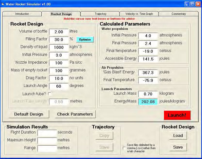
First of all you need to install the software using the standard Windows installer.
When you launch the software and you will be faced with a screen similar to the
following.
First of all…
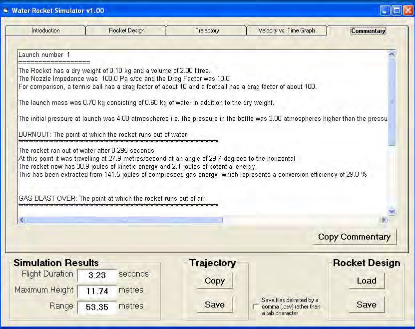
You probably feel tempted to click the big red ‘Launch’ button. Well go ahead! The
application will switch screens to show you the calculated trajectory of the rocket
with the design parameters on the left-hand side of the window above. The key
predictions for the flight duration, maximum height and range can be seen in the
lower left of the screen.
The basic idea of the program is that you:
• design a ‘virtual’ rocket by choosing values for some key parameters;
• launch your ‘virtual’ rocket by clicking the launch button
• look at the results and revise your design.
32This cycle of design/experiment/measurement of results/re-design is the fundamental
process of engineering. The purpose of the software is to speed up the design cycle,
allowing you to focus your real design efforts on those parameters likely to have the
most effect on your real rocket.
Rocket Design Tab
The left-hand side of the screen features the
parameters that you can control. They are all
inside a Rocket Design control box.
Holding the cursor over a text box will bring
up a short help message.
Most of the parameters are easy to estimate,
but some are not so easy. In particular, the
Nozzle Impedance and the Drag Factor can
be problematic.
The nozzle impedance is a number which
characterises how many cubic centimetres
of water leave the nozzle per second per
pascal of pressure difference between the
inside and outside of the rocket.
Using typical figures, a pressure of 1 atmosphere (100000 Pa) causes 100 cubic
centimetres of water to leave the rocket in about 0.1 seconds, a flow rate of 1000
cubic centimetres per second. So this corresponds to an impedance of 100000/1000 =
100 Pa s/cc. Increasing the nozzle impedance reduces the flow of water for a given
pressure difference.
33You can also read