100Gbps DMT ASIC for Hybrid LTE-5G Mobile Fronthaul Networks
←
→
Page content transcription
If your browser does not render page correctly, please read the page content below
JOURNAL OF LIGHTWAVE TECHNOLOGY, VOL. 39, NO. 3, FEBRUARY 1, 2021                                                                                   801

      100Gbps DMT ASIC for Hybrid LTE-5G Mobile
                 Fronthaul Networks
           Son Thai Le , Member, IEEE, Tomislav Drenski, Andrew Hills, Malcolm King, Kwangwoong Kim,
                                     Yasuhiro Matsui , and Theodore Sizer

                                                                   (Post-Deadline Paper)

   Abstract—Multiple access interfaces are required to provide the                 the deployments of the Fifth Generation (5G) mobile communi-
wireless coverage and capacity that operators need for consistent                  cation systems. In comparison to previous mobile generation
service across their geographic footprint. As a consequence, future                systems, e. g. 2G, 3G and 4G, the 5G distinguishes itself
radio access networks will be hybrid 4G/LTE-5G networks. This
technology evolution is creating many challenges in the mobile                     by supporting versatile services including not only enhanced
fronthaul (MFH) networks to support the co-existence of common                     mobile broadband (eMBB), but also massive Machine Type
public radio interfaces (CPRI) and evolved common public radio                     Communication (mMTC) and Ultra-Reliable and Low Latency
interfaces (eCPRI) traffic with diverse connectivity requirements in               (URLLC) services [1]. To effectively support these services,
term of capacity and reach. To address these challenges, this paper                5G networks promise 1000 times more cell capacity, 100 times
introduces a 100 Gb/s discrete multi-tone modulation (DMT) ASIC
which has been designed and fabricated in 16 nm CMOS process,                      higher peak rates, 10 times lower latency, and 10 times better
specifically targeting MFH applications. This DMT ASIC can flex-                   reliability than current 4G networks [2]. For eMBB services, the
ibly support various important data rates in hybrid 4G/LTE-5G                      target maximum user throughput is as high as 20 Gbit/s at the
MFH networks, including CPRI-10, 25 GbE, 50 GbE, 75 GbE,                           final phase of 5G, which would be achieved by leveraging new
and 100 GbE (eCPRI rates) over the full industrial temperature                     frequency bands, especially the mmWave band, and massive
range (−40 °C to +85 °C). We demonstrate the high performance
and reliability of this DMT ASIC in several real time transmission                 Multi-input Multi-output (MIMO) technology.
experiments, including: i) 200 Gb/s LAN-WDM2 transmission over                        Full deployment of 5G networks is a complex and expensive
20 km in O-band using two 25-GHz class directly modulated lasers                   process, which will take many years to complete. In addition,
(DMLs); and ii) 200 Gb/s, 300 Gb/s and 400 Gb/s WDM transmis-                      monolithic and homogeneous networks, including 5G networks,
sions over up to 40 km in C-band using 4 wavelengths, each with                    are no longer capable of addressing our growing and increasingly
data rate of 50 Gb/s, 75 Gb/s, and 100 Gb/s, respectively. The success
of these experiments clearly indicates the attractiveness of the                   diverse mobile device and connectivity needs in a satisfactory
presented DMT ASIC for future MFH applications. In addition, in                    way. In this aspect, legacy infrastructure, especially 4G net-
several transmission scenarios, the advantages of DMT format over                  works, will continue to have a crucial role in the hybrid wireless
conventional PAM4 format for MFH applications are highlighted.                     access networks with multiple access interfaces to provide the
  Index Terms—5G, direct detection, Discrete Multi-Tone format,                    coverage and capacity that operators need for consistent service
eCPRI, hybrid LTE-5G networks, LTE, mobile fronthaul.                              across their footprint.
                                                                                      In fact, a big part of the 5G applications market is driven by
                                                                                   the evolution of 4G/LTE (Long Term Evolution). Technology
                            I. INTRODUCTION                                        improvements of 4G/LTE are ongoing, and it will continue to
         ANY operators around the world (e. g. from South                          be relied upon for many applications and services for a long
M        Korea, China, and the United States) have already started                 time. Accordingly, operators will continue to optimize LTE
                                                                                   capabilities such as improved uplink capacity to support video
                                                                                   and wireless communication to cloud-based applications and
   Manuscript received July 30, 2020; revised September 30, 2020, Novem-           coordinated multipoint (CoMP) transmission. LTE adoption will
ber 16, 2020, and December 9, 2020; accepted December 10, 2020. Date of
publication December 14, 2020; date of current version February 2, 2021.           proceed at a fast pace with many innovations overlapping with
(Corresponding author: Son Thai Le.)                                               5G operations. Thus, over the next decade, operators will keep
   Son Thai Le, Kwangwoong Kim, and Theodore Sizer are with Nokia                  on deploying, upgrading and improving their 4G networks in
Bell Labs, Holmdel NJ 07733 USA (e-mail: son.le@nokia-bell-labs.com;
kw.kim@nokia-bell-labs.com; theodore.sizer@nokia-bell-labs.com).                   parallel with the deployment of 5G networks. This evolution
   Tomislav Drenski, Andrew Hills, and Malcolm King are with the So-               in hybrid LTE-5G networks is having a strong impact on every
cionext Europe GmbH, Maidenhead SL6 4FJ, U.K. (e-mail: tomislav.                   aspect of the overall radio access network (RAN), including the
drenski@socionext.com; andrew.hills@socionext.com; malcolm.king@socio
next.com).                                                                         mobile fronthaul (MFH) and mobile backhaul (MBH) segments.
   Yasuhiro Matsui is with II-VI Incorporated, Fremont, CA 41762 USA (e-mail:         Cloud radio access network (C-RAN), sometime referred to
yasuhiro.matsui@finisar.com).                                                      as Centralized RAN, has been widely considered as the main
   Color versions of one or more of the figures in this article are available at
https://doi.org/10.1109/JLT.2020.3044516.                                          architecture for 4G/LTE and 5G networks [3]–[4] due to its
   Digital Object Identifier 10.1109/JLT.2020.3044516                              significant benefit in capital and operation expenditure savings.

                         0733-8724 © 2020 IEEE. Personal use is permitted, but republication/redistribution requires IEEE permission.
                                       See https://www.ieee.org/publications/rights/index.html for more information.

               Authorized licensed use limited to: Socionext. Downloaded on January 23,2021 at 12:14:08 UTC from IEEE Xplore. Restrictions apply.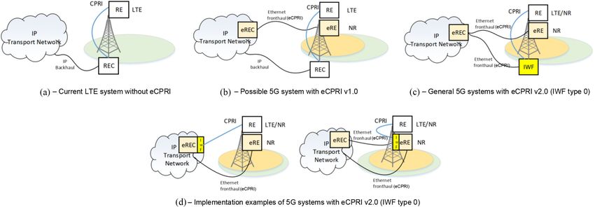
802 JOURNAL OF LIGHTWAVE TECHNOLOGY, VOL. 39, NO. 3, FEBRUARY 1, 2021
In addition, C-RAN can also enhance the network’s capacity and 4 × 25 Gb/s eCPRI or 4 × 24.33 Gb/s CPRI-10 traffic on a single
performance through load balancing and combined processing optical wavelength. In addition, this ASIC can be operated in
of radio signals from several closely located base stations [5]– 1 × 25 Gb/s, 2 × 25 Gb/s and 3 × 25 Gb/s transmission modes,
[6]. In C-RAN, most of the signal processing functions on radio providing great flexibility for mobile network operators. Using
signals are performed from remotely located baseband units this ASIC, we demonstrate real-time 200 Gb/s transmission in
(BBUs), which are connected to lightweight remote radio heads O-band and 400 Gb/s transmission in C-band over up to 40 km.
(RRHs) through MFH networks. For 4G/LTE MFH networks, The paper is organized as follows: Section II discusses the co-
Common Public Radio Interface (CPRI) has been considered as existence of CPRI and eCPRI traffic in hybrid LTE-5G networks;
the mainstream transport protocol [7]. The latest CPRI specifica- Section III discusses the benefit of DMT over the conventional
tion specifies CPRI line rates up to 24.33 Gbit/s (CPRI Rate 10) PAM4 format in fronthaul applications; Section IV presents
[7] which pumps more capacity to the LTE RRH for achieving the architecture and characterization of 100 Gb/s DMT ASIC;
higher order MIMO and multi-carrier configuration. However, Section V presents experimental setup and real-time trans-
as the CPRI data rate scales with the number of antennas rather mission results for various practically relevant configurations;
than the number of MIMO layers, the required CPRI data rates Section VI concludes the paper.
in 5G systems with massive MIMO are in the order of several
hundreds of Gb/s [7]. This extremely high data rate makes it
challenging for implementing MFH networks in a cost-effective II. FRONTHAUL TRANSPORT IN HYBRID LTE-5G NETWORKS
manner. As mentioned earlier, CPRI has been used as the main trans-
To address this problem, the 3rd generation partnership port protocol for 4G/LTE MFH networks as shown in Fig. 1a,
project (3GPP) has identified eight different functional split op- where the LTE RE is connected to LTE REC via a point-to-point
tions between the CU and RU for the 5G New Radio (NR) [8], out CPRI link. Compared to CPRI, eCPRI makes it possible to
of which “Option 1” denotes the classical backhaul and “Option decrease the required data rate between eREC and eRE via
8” the physical layer (CPRI) approach. A new specification for flexible functional decomposition while limiting the complexity
MFH including these function splits called enhanced CPRI or of the eRE [9]. This is a crucial feature making eCPRI suitable
evolved CPRI (eCPRI) has also been introduced [9]. Out of eight for 5G networks with massive MIMO. Alternatively, in recent
function split options specified by 3GPP, the most prominent years, several spectral-efficient MFH transport schemes, such
option appears to be the option 7 (intra PHY layer split) as it can as radio-over-fiber (RoF) [15]–[17] and intermediate frequency
reduce the fronthaul capacity by an order of magnitude while over fiber (IFoF) [18]–[20] have been actively investigated.
still effectively supporting features such as Carrier Aggregation, However, compared to these schemes, eCPRI provides an im-
Network MIMO, Downlink CoMP and Uplink L1 joint process- portant advantage that eCPRI data is encapsulated in Ethernet
ing [8]–[9]. In addition, with eCPRI protocol, fronthaul traffic frames and can be transported via a packet-based transport net-
now can be encapsulated in Ethernet frames and subsequently work. This effectively positions Ethernet as convergence layer
transported via Ethernet and Ethernet/IP/UDP networks. for consolidating backhaul, fronthaul and possibly other packet
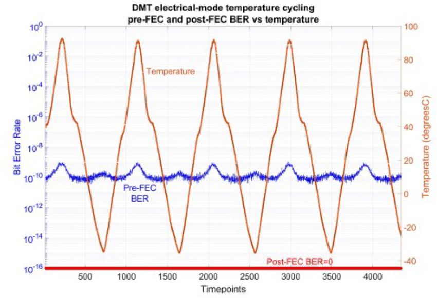
Unfortunately, eCPRI is not backward compatible with CPRI. traffic, providing great flexibility and efficiency.
To enable the co-existence of CPRI and eCPRI traffic in hy- On the other hand, as eCPRI is not backward compatible
brid 4G/LTE-5G fronthaul networks, eCPRI specification v2 with CPRI, eCPRI specification v1 suggests that CPRI and
[10] has specified an Interworking function (IWF), acting as eCPRI traffic are managed separately (Fig. 1b). In this case,
a CPRI/eCPRI bridge. More specifically, an IWF can be con- mobile operators have to manage both REC and eREC, and in
nected with both LTE Radio Equipment (RE) through a CPRI many cases, in separate physical locations, which is very ineffi-
point-to-point link, or with an (enhanced) Radio Equipment cient. To address this issue, eCPRI specification v2.0 specifies
Control (eREC) via a packet-based transport network. In this CPRI/eCPRI traffic mapping through an IWF, by which a RE
scenario, having optical transceivers which can support both can be connected to an eREC (IWF type 0) as shown in Fig. 1c.
CPRI-10 and eCPRI Ethernet traffic is strongly desirable as they In this case, the REC can be integrated and managed together
simplify the network deployment and planning. In addition, such with the eREC. Two example of implementation options (at the
optical transceivers can be re-used when a RE is upgraded to an logical data plane) are shown in Fig. 1d [10], namely i) – IWF
eRE to support 5G New Radio (NR) services. This represents is integrated with eREC and is connected to a LTE RE via a
a significant saving in capital expenditure. As a result, several point-to-point CPRI link (usually via a fiber optical cable) and
optical module vendors have already started developing a new ii) – IWF is integrated with 5G eRE and connected with LTE RE
class of optical transceivers with selectable retiming and data via a short CPRI link (can be via either a fiber optical cable or an
clock recovery to support both 25GbE eCPRI and CPRI-10 electrical cable). These two implementation options are different
traffic [11]–[12]. To further reduce the cost and support future in terms of transceiver requirements. For example, in the first
bandwidth-hungry applications, it would be strongly desirable implementation scenario, one pair of optical CPRI transceiver
to increase the data rate of such optical transceivers to 100 Gb/s. and one pair of eCPRI transceivers providing similar reach
This paper is an extended version of our conference pa- are required. In the second implementation scenario, two pairs
per [13], presenting the industry-first 16 nm complemen- of long-reach eCPRI transceivers and one pair of short-reach
tary metal-oxide-semiconductor (CMOS) ASIC [14] using a CPRI transceiver are required if CPRI and eCPRI traffic are
Discrete Multi-Tone (DMT) format that can support either to be transmitted separately. In terms of hardware requirement,
Authorized licensed use limited to: Socionext. Downloaded on January 23,2021 at 12:14:08 UTC from IEEE Xplore. Restrictions apply.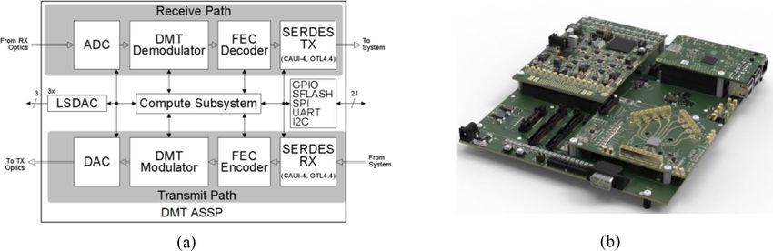
LE et al.: 100GBPS DMT ASIC FOR HYBRID LTE-5G MOBILE FRONTHAUL NETWORKS                                                                             803

Fig. 1.   Possible CPRI/eCPRI migration scenarios in hybrid 4G/LTE-5G MFH networks [10]; IWF – Interworking function.

                                                                                    In conventional IM/DD transmission systems, one can express
                                                                                 the amplitude of the optical field after modulation as:
                                                                                                            s (t) = A + m (t) .                     (1)
Fig. 2. Block diagram of a conventional IM/DD transmission scheme; PD –          where m(t) is the real-valued modulated signal with zero mean
photodiode.
                                                                                 and A represents the amplitude of the optical carrier which is
                                                                                 big enough such that the condition s(t) ≥ 0 is satisfied.
                                                                                   For simplicity of the analysis, it is assumed that the fiber
it is clear that the first option is advantageous as it requires
                                                                                 channel is characterized only by the CD. In this case, the time
one pair less of optical transceivers and it minimizes the power
                                                                                 impulse response of the channel can be expressed as [22]:
consumption and complexity of eRE. This option highlights the
important roles of both CPRI and eCPRI optical transceivers                                                  c          jπc
                                                                                                h (t) =          exp         t .              (2)
in the hybrid 4G/LTE-5G MFH networks. In this case, a new                                                  jDλ2         Dλ2
class of optical transceivers with selectable retiming and data
                                                                                 where D (ps/nm) is the total chromatic dispersion of the link, λ
clock-recovery to support both CPRI (most likely CPRI-10)
                                                                                 (nm) is the optical wavelength and c (m/s) is the speed of light.
and eCPRI traffic would be of great interest. Such transceivers
                                                                                    In the frequency domain, the fiber channel response can be
are available on the market, offering data rate of 25 Gb/s on
                                                                                 obtained by taking the Fourier Transform of the Eq. (2), showing
one optical wavelength using NRZ format [11]–[12]. The next
                                                                                 a characteristic of an all-pass filter:
common step would be to increase the data rate to 100 Gb/s to

support future bandwidth-hungry applications. In term of reach                                                         jDλ2 2
                                                                                                   H (ω) = exp −             ω .               (3)
requirement, the majority of fronthaul connections in C-RAN                                                              4πc
LTE/5G networks are within the range of 10 km – 40 km. The
upper limit on the fronthaul link distance is determined based                   where ω = 2πf is the angular frequency.
on the latency requirement of the RANs.                                            The received signal at the end of the fiber link can be simply
                                                                                 written as:

          III. DMT FOR HYBRID LTE-5G MFH NETWORKS                                           r (t) = s (t) ⊗ h (t) = (A + m (t)) ⊗ h (t) .           (4)

A. Power Fading in IM/DD Transmissions                                           where ⊗ stands for the convolution operation.
                                                                                   The detected photocurrent is the intensity of r(t):
   Due to the cost-sensitive nature of radio access networks,
optical transceivers for MFH applications have to be low-cost.                      I (t) = |A|2 + |m (t) ⊗ h (t)|2 + 2A · R (m (t) ⊗ h (t)) .
As a consequence, CPRI and eCPRI transceivers have been                                                                                       (5)
designed using the conventional intensity modulation – direct                    where  stands for the real part.
detection (IM/DD) transmission scheme where the detection is                        Equation 3 shows that the detected current in an IM/DD
performed by a single-ended photodiode (PD) [21] (Fig. 2).                       transmission system is the sum of three terms. The first term
This transmission scheme is strongly dependent and affected                      I1 (t) = |A|2 is the DC part which does not have any im-
by the fiber chromatic dispersion (CD). For the sake of the                      pacts on the system performance. The second terms I2 (t) =
completeness, in this section, we review some basic properties                   |m(t) ⊗ h(t)|2 is the signal-signal self-beating term. The third
of the IM/DD channel and explain why DMT is a very attractive                    term I3 (t) = 2A · (m(t) ⊗ h(t)) represents the linear detec-
modulation format for MFH networks.                                              tion term impaired by the fiber CD, which is also the dominant

               Authorized licensed use limited to: Socionext. Downloaded on January 23,2021 at 12:14:08 UTC from IEEE Xplore. Restrictions apply.
804 JOURNAL OF LIGHTWAVE TECHNOLOGY, VOL. 39, NO. 3, FEBRUARY 1, 2021
Fig. 4. Frequency of the first notch as function of distance for IM/DD trans-
mission system in C-band.
the signal’s bandwidth. The amplitude response of the linear
detection term is shown in Fig. 3(b).
A major issue associated with the power-fading effect is that
the faded frequency components cannot be recovered through
conventional receiver equalizers. This will limit the usable band-
width of the IM/DD channel from DC to the first notch when
Fig. 3. (a) Electrical spectra of 112 Gb/s 4-level pulse-amplitude modulation the signal is modulated using conventional modulation formats
(PAM4) signal with raised-cosine (RC) pulse shaping at the transmitter and after such as non-return to zero (NRZ) and PAM4. Such limitation in
PD over 20 km of standard single mode fiber (SSMF) in C-band; (b) – amplitude the usable bandwidth subsequently reduces the achievable data
response of the linear detection term impaired by the CD.
rate of the IM/DD transmission system.
Figure 4 shows the first frequency notch as function of dis-
term in the detected photocurrent. Taking the Fourier transform tance for IM/DD systems in C-band. One can note that at 20 km
of this term, we obtain: the usable system bandwidth is up to ∼13 GHz, which might
restrict the achievable data rate of the system to be below 50 Gb/s
Dλ2 2 πDλ2 2
I3 (ω) = M (ω) · cos ω = M (ω) · cos f . when PAM4 format is used. For 100 Gb/s PAM4 IM/DD sys-
4πc c tems, the required electrical bandwidth is around 25 GHz, which
(6)
might impose a limitation in the reach of ∼6 km, according to
where M (ω) is the spectrum of the modulated signal m(t).
Fig. 4.
From Eq. (6), considering only the linear detection term, the
In summary, the estimated reach of 50 Gb/s and 100 Gb/s
channel response of the DD channel can be expressed as:
PAM4 IM/DD systems based on the location of the first notch
πDλ2 2 are below 20 km and 6 km respectively, which is not sufficient
R (f ) = cos f . (7)
c for supporting MFH links in hybrid 4G/LTE-5G networks. In-
creasing further the reach of IM/DD systems in C-band requires
It is evident that this channel response has notches (R(f ) = mitigating the impact of the power fading effect. Alternatively,
0) at the following frequencies: IM/DD systems for fronthaul applications can be implemented
(2n + 1) c in O-band where the chromatic dispersion is minimal. However,
fn = , n = 0, 1, 2. (8) due to the lack of cost-effective O-band amplifiers and tunable
2λ2 D
O-band laser sources, only a limited number of wavelengths
This result indicates that at several frequencies, the trans- in O-band (up to 8 wavelengths in LAN-WDM8 scheme) can
mitted signal is completely faded after propagating through an be used for transmissions [24] (Grey optic). In this case, Grey
IM/DD channel. In addition, frequency components around the optic can deliver a total capacity per fiber up to 400 Gb/s. In
notches are attenuated causing a significant loss in the signal the context of LTE/5G networks, this capacity (up to 400 Gb/s)
power. This phenomenon is usually called CD-induced power might not be sufficient. Operators will either need to rent more
fading effect [24], which is a major effect limiting the perfor- fibers or to leverage a more expensive transmission technology
mance of IM/DD transmission systems. such as coherent detection. This situation is undesirable from a
Figure 3(a) shows the electrical spectrum of 112 Gb/s 4-level cost point of view.
pulse-amplitude modulation (PAM4) signal with raised-cosine
(RC) pulse shaping over 20 km of standard single mode fiber
(SSMF) in C-band (D = 340 ps/nm), where several notches B. Discrete Multi-Tone Modulation
falling into the signal’s bandwidth can be observed. An RC pulse The power fading effect just described in IM/DD transmission
shaping was chosen with a small roll-off factor of 0.05 so that the systems is similar to the multi-path fading effect in wireless
signal-signal self-beating term can be clearly observed outside communication [25]. To maximize the transmission capacity
Authorized licensed use limited to: Socionext. Downloaded on January 23,2021 at 12:14:08 UTC from IEEE Xplore. Restrictions apply.LE et al.: 100GBPS DMT ASIC FOR HYBRID LTE-5G MOBILE FRONTHAUL NETWORKS 805
Fig. 5. General block diagram IM/DD transmission with DMT format; P/S and S/P– serial to parallel and parallel to serial conversions; CP – cyclic prefix; BL/PL
– bit and power loading; Conj – conjugation operation.
of fading channels, wireless communication systems (e. g. 5G
systems) use a multicarrier modulation format called orthogonal
frequency division multiplexing (OFDM) [26]. OFDM encodes
digital data on multiple carrier frequencies and optimizes the
data rate on each carrier frequency based on the fading profile
of the channel. Due to its superior performance, OFDM format
has been chosen as the standard signaling technique for 5G
NR. Based on the success of OFDM, for IM/DD transmission
systems, a special version of OFDM called DMT has been
intensively investigated [27]–[30]. A general block diagram of
an IM/DD transmission scheme with DMT format is shown in
Fig. 5. DMT divides the frequency spectrum into orthogonal
subcarriers but it employs the properties of Hermitian symmetry
and the inverse discrete Fourier transform (IDFT) to create a Fig. 6. Sensitivities at BER of 0.004 for 112 Gb/s DMT and 112 Gb/s PAM4
real-valued signal which is required for IM/DD systems [27]. systems as functions of total dispersion of the link.
Each subcarrier can be modulated with a quadrature amplitude
modulation (QAM) format and the power of each subcarrier can CD is increased further, the performance of the PAM4 system
be allocated using a water filling algorithm [31] to maximize is quickly degraded and the system breaks down when the first
the system’s capacity in the presence of power-fading effects. notch appears within the signal bandwidth. Due to the ability
This process is known as bit and power loading (BL, PL). of optimizing BL/PL based on the channel response (changing
BL/PL effectively minimize the impact of notches due to the with the link distance), DMT can tolerate a much higher CD,
power fading effect and extend the usable bandwidth in a DMT up to 240 ps/nm when accepting a ∼2 dB penalty in sensitivity.
IM/DD system beyond the first notch’s frequency. In addition, This result clearly shows a significant benefit of DMT format
this technique also mitigates the impact of bandwidth limitations over PAM4 for IM/DD transmission systems. On the other hand,
of opto-electronic components in the system. At the receiver, the the DMT format has higher requirements on the dynamic range
total channel response can be compensated effectively using a and on the linearity of the opto-electronic components due to
simple 1-tap equalizer. its higher peak-to-average power ratio (PAPR) compared to
The benefit of DMT format over the conventional PAM4 those of PAM4 format. This is the main reason that practical
format for IM/DD systems is shown in Fig. 6, where the required implementations of the DMT format in IM/DD systems for data
optical power as function of total dispersion of the link for center and other short-reach applications are limited.
112 Gb/s DMT and 112 Gb/s PAM4 systems are compared
through simulation. For the 112 Gb/s DMT system the IDFT
size was 512 and the number of modulated subcarriers was 250. IV. 100 GB/S DMT ASIC
The transmitter’s bandwidth limitation was modelled using the There are practical applications in hybrid 4G-LTE/5G net-
first order Gaussian filter with a 3-dB bandwidth of 16 GHz. works that can highly benefit from the DMT solution. In the
The fiber channel includes only CD, the receiver includes both following investigations, a 100 Gb/s DMT ASIC has been used
shot noise and thermal noise from a TIA with resistor of 20 that is designed and fabricated in 16 nm complementary metal-
kΩ and a noise figure of 5 dB. For 112 Gb/s PAM4 system a oxide-semiconductor (CMOS) technology [14]. Some prelim-
feed-forward equalizer (FFE) with 127 T/2-space taps was used inary transmission measurements using this DMT ASIC have
for signal equalization. A long filter had to be used to make been also reported in [32]. The block diagram of the DMT ASIC
sure that the best possible performance of PAM4 system was is depicted in Fig. 7(a). It can support various client interfaces,
achieved. For the DMT system, a single-tap equalization was including CPRI-10, 100 GbE (IEEE CAUI-4 compliant) and
used. It is evident that when the CD is small (up to ∼40 ps/nm) OTL4.4. The ASIC can be operated at ¾, ½ and ¼ client rates
both systems offer very similar sensitivities. However, when the (75 Gb/s, 50 Gb/s and 25 Gb/s) providing a great flexibility
Authorized licensed use limited to: Socionext. Downloaded on January 23,2021 at 12:14:08 UTC from IEEE Xplore. Restrictions apply.806 JOURNAL OF LIGHTWAVE TECHNOLOGY, VOL. 39, NO. 3, FEBRUARY 1, 2021
Fig. 7. (a) General block diagram of the 16nm CMOS ASIC; (b) – Picture of the ASIC evaluation board
for 5G MFH applications. As a 25 Gb/s rate would be enough between initializations. For this reason, the latency variation was
to support eCPRI traffic of a typical 5G radio unit employing measured across multiple initializations; a long-sequence PRBS
the splitting option 7.3 with a 100 MHz carrier, 8 spatial layers data stream input to the transmitter of one DMT chip and the
and a 64 transmit/receiver antenna [10]. A typical small cell-site output PRBS data stream from a connected receiver DMT chip
consists of 3 sectors and can be supported by a single 75 Gb/s were both captured in the time-domain and the resulting delay
DMT system. In a macro cell, more sophisticated traffic aggre- between them was accurately measured. For any one particular
gation schemes can be used and 100 Gb/s per wavelength system initialization the latency variation is small, with typically 130
can provide significant cost saving. All of these scenarios can be ps change measured when subjected to a temperature change
effectively supported by this DMT ASIC, making it an attractive from 25 °C to 100 °C, demonstrating an excellent stability. Fig-
and viable solution for hybrid 4G/LTE-5G networks. ure 8(a) then shows the latency variation observed across 200
The ASIC incorporates a complete single channel DMT trans- initializations of the DMT ASIC, the resulting variation is less
mission PHY for up to 100 Gb/s data rates over short reach than ±3 ns (Fig. 8a). This value is well below 65 ns, which is
optical fiber. It includes an 8-bit Digital-to-Analog Converter the maximum allowed time alignment error between antenna
(DAC) and Analog-to-Digital Converter (ADC) with sampling ports in 5G networks [33], confirming that the latency variation
rates up to 71 GS/s, a DMT core engine, an on-chip digital contribution of the DMT ASIC is small relative to the total
RX timing recovery, a low-jitter RX clock generation and high allowed latency variation budget of the system.
coding gain FECs. The DMT core engine at the transmitter Figure. 8(b) shows the variation in performance in terms of
side uses 512pt iFFT to encode data onto 256 subcarriers with measured chip temperature and pre-FEC BER and post-FEC
adaptive QAM formats with 0-8 bits per subcarrier. For achiev- BER of the DMT ASIC in the electrical back to back configura-
ing the best transmission performance, the QAM modulation is tion when the temperature is swept from −40 °C to +85 °C (each
determined by measuring the signal-to-noise ratio (SNR) of the time point is 10 s). One can note that the pre-FEC BER slightly
channel at each subcarrier frequency. A water-filling algorithm increases at high temperature, but the rise is insignificant as it
then computes the bit and power loading for each subcarrier is always below 10−9 , and the slight variation does not have
and an adaptive background equalization guarantees optimum any impact on the post-FEC BER. This result confirms that
adaptation to any variations in the channel. The DMT ASIC also the ASIC performs stably over the full industrial temperature
includes configurable cyclic prefix for total bitrate optimization range (−40 °C to+85 °C), therefore qualifying for fronthaul
and frequency domain equalization. The receive path accepts a applications in uncooled outdoor enclosures.
DMT modulated electrical signal which is sampled and digitized
by the ADC. The DMT data stream is then demodulated, back V. EXPERIMENTAL DEMONSTRATIONS
to the original time domain-based data before running through
the FEC decoder to ensure error free data is passed to the client A. O-Band Transmission
interface. The first experiment was to evaluate the performance of
To meet the strict requirements of LTE/5G fronthaul networks, the DMT ASIC in O-band (Grey optic) applications. For this
the DMT ASIC was designed to achieve low latency variation transmission scenario, a directly modulated laser (DML) is the
and stable performance over the full industrial temperature range preferred optical modulator due to several reasons: i) – DML
(−40 °C to +85 °C). All DSP operations of the DMT chip is a low cost solution since the optical signal is modulated
(including DMT framing/deframing, bit mapping/demapping by directly modulating the injected current of the laser and no
and FEC coding/decoding) were designed to operate in a fixed external modulator is required; ii) – DML offers higher optical
number of clock cycles and contribute no latency variation; output power than external modulated lasers (EMLs), which
additionally the transparent nature of the DMT transmission subsequently increases the system reach in the O-band.
means that latency is unaffected by the format or framing of the For the experiment in O-band, a 200 Gb/s LAN-WDM2 real
carried data and all data bits experience the same ‘bit-latency’. time transmission over 20 km of SSMF was tested using two
The remaining source of latency variation is due to on-chip 25-GHz-class DMLs at 1305 nm and 1310 nm with + 8 dBm
FIFO’s whose delay is stable once initialized but can change of optical output power (when the DML is bias at 70 mA).
Authorized licensed use limited to: Socionext. Downloaded on January 23,2021 at 12:14:08 UTC from IEEE Xplore. Restrictions apply.LE et al.: 100GBPS DMT ASIC FOR HYBRID LTE-5G MOBILE FRONTHAUL NETWORKS 807
Fig. 8. (a) Latency variation measurement of the DMT ASIC; (b) – Electrical mode temperature cycling pre-FEC and post-FEC BER measurement versus
temperature.
Fig. 9. Experimental setup of real time O-band, amplifier-less, LAN-WDM2 200 Gb/s transmission supporting 8 × 25 GbE Ethernet or 8 × 24.33 Gb/s CPRI-10
traffic over 20 km.
This system can support 8 eCPRI channels at 25 Gb/s or 8
CPRI-10 channels. The experimental setup is shown in Fig. 9
having two DMT ASICs operating at full rate of 4 × 25 Gb/s
(supporting eCPRI traffic) and 4 × 24.33 Gb/s (supporting
CPRI-10 traffic). For each channel, the appropriate CPRI-10
traffic at 4 × 24.33 Gb/s and eCPRI Ethernet traffic at 4 ×
25.78125 Gb/s (IEEE CAUI-4 compliant) was emulated, which
were then mapped onto 256 subcarriers (after FEC-encoding) by
the DMT core engine through bit and power mapping based on
the channel condition measured during the initialization stage.
During operation, the channel condition was automatically
tracked and updated by the DMT core engine after a predefined
(adjustable) time interval. The modulated DMT signal of the Fig. 10. Opto-electronic responses of 1310 nm and 1305 nm channels.
ASIC was amplified using a 25-GHz RF driver to a Vpp of ∼4.5
V before bias-adding for directly driving a DML. The TX 3-dB
bandwidth for each channel was ∼16 GHz (Fig. 10). below 0.04 (CI-BCH FEC limit) corresponded to the post-FEC
After optical modulation, the two optical channels were com- BER value below 10−15 . Fig. 11(a) and Fig. 11(b) depict the back
bined using a LAN-WDM MUX and then fed into 20 km of to back (B2B) measurements for 1310 nm and 1305 nm chan-
standard single mode fiber (SSMF). At the receiver, two DMT nels, showing excellent sensitivities of ∼−6 dBm and −7 dBm
channels were demultiplexed using a LAN-WDM DeMUX. for 4 × 25 Gb/s (eCPRI traffic) and 4 × 24.33 Gb/s (CPRI-10
Each channel was detected using a 25-GHz PIN-TIA receiver traffic), respectively. For the 4 × 25 Gb/s transmission scenario,
and then fed back into the ASIC for real-time processing and the firmware provided an option of varying the DAC sampling
decoding. The total insertion loss of the link, including 20 km rate from 64 GS/s to 71 GS/s. Fig. 11(a)–Fig. 11(b) show that
of SSMF and LAN MUX/DEMUX in the O-band was ∼10 dB, increasing the DAC sampling rate significantly increases the
providing a maximum received optical power for each channel system’s performance. This is due to the fact that the signal band-
of ∼−2 dBm. width is expanded when the DAC sampling rate is increased. In
The overall experimental results for the O-band transmission DMT transmissions, given a fixed data rate, increasing the usable
are depicted in Fig. 11. Herein the pre-FEC BER was used as bandwidth improves the overall transmission performance. This
the performance metric. Important to note is that the FEC was is a major advantage in performance and flexibility of DMT com-
applied in all transmission cases and all reported pre-FEC BER pared to the PAM4 format where increasing the bandwidth does
Authorized licensed use limited to: Socionext. Downloaded on January 23,2021 at 12:14:08 UTC from IEEE Xplore. Restrictions apply.808 JOURNAL OF LIGHTWAVE TECHNOLOGY, VOL. 39, NO. 3, FEBRUARY 1, 2021
Fig. 11. Overall experimental results for 200 Gb/s transmission in O-band including (a)–(b) – B2B sensitivities of 1310 nm and 1305 nm channels, respectively;
(c)–(d) SNR and allocated bits per subcarrier for the 1310 nm channel at 0 dBm of Rx power;
not necessarily increase the system’s performance because of the
power fading effect. For the 4 × 24.33 Gb/s transmission mode,
the DAC sampling rate was fixed at 64 GS/s. This limitation was
due to the firmware used at the time of experiment. However, due
to the slightaly smaller data rate, the 4 × 24.33 Gb/s transmission
mode with a DAC sampling rate of 64 GS/s still performs better
than 4 × 25 Gb/s mode with a DAC sampling rate of 71 GS/s.
Figure 11c shows the typical SNR profile of the IM/DD chan-
nel for 4 × 24.33 Gb/s transmission mode (DAC sampling rate
of 64 GS/s) and 4 × 25 Gb/s transmission mode (DAC sampling
rate of 71 GS/s). Due to the different DAC sampling rates used,
the subcarrier spacings in these cases was also different (the
subcarrier spacing is proportional to the DAC sampling rate).
Based on this SNR profile the DMT engine optimizes the BL for
each subcarrier for minimizing the pre-FEC BER. The resulting Fig. 12. Performance over 20 km of 200 Gb/s LAN-WDM2 transmission.
BL profiles for 4 × 24.33 Gb/s and 4 × 25 Gb/s transmission
modes are shown in Fig. 11d. These BL profiles show that most
of the first 64 subcarriers are transmitted with 64 QAM format. ASIC for C-band transmission applications, a 4-channel WDM
Subcarriers from 90 to 160 are loaded mostly with 16 QAM transmission as shown in Fig. 13 was set up. The ASIC was used
format following by 8 QAM and QPSK. to modulate two interleaved optical carriers (either 1545 nm with
Figure 12 depicts the overall performances of 4 × 24.33 Gb/s 1557 nm or 1549 nm with 1561 nm) using a Mach-Zehnder
and 4 × 25 Gb/s transmission modes over 20 km for both 1310 Modulator (MZM). After multiplexing, the WDM signal was
nm and 1305 nm channels. Compared to the B2B cases, the amplified and fed into a single span of SSMF with span length
sensitivity is reduced by ∼1 dB, to – 6 dBm for all consid- from 10 km to 40 km. Various net data rate settings of the DMT
ered transmission scenarios. Given the fact that the maximum ASIC, namely 50 Gb/s (2 × 25 Gb/s), 75 Gb/s (3 × 25 Gb/s) and
received optical power was around −2 dBm, there is still 4 dB 100 Gb/s (4 × 25 Gb/s and 4 × 24.33 Gb/s) were considered.
power margin for practical implementations. This high-power When the data rate of the DMT ASIC was 75 Gb/s or below,
margin confirms the reliability and usability of the DMT ASIC no DCF was used. At the receiver, each channel was filtered
for real transmission systems. out using a 0.7 nm tunable optical filter where the filter’s center
frequency was tuned to the carrier frequency of the DMT signal.
In this case, the full DMT signal passed through optical filter
B. C-Band Transmissions With Double Sideband DMT
before being detected using a PIN-TIA photo-receiver. With this
As discussed in Section II, many MFH links in 4G/LTE-5G filter setting, the system is usually referred to as double sideband
networks will require extremely high transmission capacity (be- (DSB) DMT.
yond 1 Tb/s). In this case, transmission in the C-band becomes For the data rate of 50 Gb/s a comparison of DMT format
necessary. To demonstrate the potential performance of the DMT (with real time processing) versus 50 Gb/s PAM4 and 50 Gb/s
Authorized licensed use limited to: Socionext. Downloaded on January 23,2021 at 12:14:08 UTC from IEEE Xplore. Restrictions apply.LE et al.: 100GBPS DMT ASIC FOR HYBRID LTE-5G MOBILE FRONTHAUL NETWORKS 809
Fig. 13. Experimental setup of real time C-band, WDM transmissions with up to 400 Gb/s supporting 16 × 25 GbE Ethernet or 16 × 24.33 Gb/s CPRI-10 traffic.
The transmission distance is from 10 km to 40 km, DCF is optional.
Fig. 14. (a) Performance comparison between 50 Gb/s DMT (real time) over
20 km and 40 km, 50 Gb/s PAM4 and NRZ (offline signal processing) for 1549 Fig. 15. (a) – Performance comparison of 75 Gb/s DMT (real time) over 10 km
nm channel over 20 km (without DCF); (b) – Bit loadings for 50 Gb/s DMT and 20 km and 75 Gb/s PAM4 (offline signal processing) for 1549 nm channel
signals over 20km (with – 1 dBm of Rx power) (upper) and 40 km (lower). over 10 km; (b) – Bit loadings for 75 Gb/s DMT signals (with – 1 dBm of Rx
power) over 10 km (upper) and 20 km (lower).
NRZ was performed and the results are shown in Fig. 14(a) for
the 1549 nm channel. For the DMT format, similar performances
were observed also for other wavelengths (not shown here). For complexity and cost of the systems. On the other hand, with
50 Gb/s PAM 4 and NRZ systems offline signal processing was DMT format, appropriate bit loading can be used to extend
used. For both cases, FFEs with an optimum length of 127 the usable bandwidth beyond the first notch. The bit loadings
T/2-space taps were used. It is evident in Fig. 14(a) that the for the cases of 20 km and 40 km transmissions are depicted
50 Gb/s systems with either PAM4 or NRZ could not reach in Fig. 14(b), where subcarriers around notches are not used
20 km without dispersion compensation because of the power while subcarriers beyond the first notch can still be used for
fading effect (the first notch appears at ∼13 GHz). As a result, data transmission. This result confirms that DMT can maximize
for 20 km MFH applications either DCF or advanced coding the usable bandwidth of the IM/DD channel and thus deliver a
are required if the conventional PAM4 format or NRZ are to much better performance in the C-band compared to PAM4. This
be used. Both options are not desirable as they increase the important feature of DMT enables 50 Gb/s transmission over
Authorized licensed use limited to: Socionext. Downloaded on January 23,2021 at 12:14:08 UTC from IEEE Xplore. Restrictions apply.810 JOURNAL OF LIGHTWAVE TECHNOLOGY, VOL. 39, NO. 3, FEBRUARY 1, 2021
Fig. 16. Overall experimental results for 400 Gb/s transmission in C-band including (a) – B2B sensitivities of 4 WDM channels; (b) – performance over 20 km;
(c)–(d) SNR and allocated bits per subcarrier for the 1549 nm channel at 0 dBm of Rx power in the B2B case.
Fig. 18. Optical spectra for DSB and VSB 100 GbE DMT signals. The central
frequency is at 1557 nm.
C-band without dispersion compensation. However, when using
the DMT format, 75 Gb/s could be transmitted successfully over
20 km. The bit loadings for 75 Gb/s DMT signal over 10 km
and 20 km are shown in Fig. 15(b). This is an important result
because 75 Gb/s is required to support a typical 5G cell with 3
sectors, each with 25 Gb/s of eCPRI traffic.
Next considerations were for the full 100Gb/s data rate of
the DMT ASIC. In this case, for the DSB-MDT signals, the
reach of at least 10 km could not be achieved without DCF
(target was set to 20 km). Therefore, to compensate the CD over
20 km a DCF with dispersion of −338 ps/nm was used. The
overall performance of 400 Gb/s WDM system in C-band is
shown in Fig. 16. In the B2B case (where the optical filter is
Fig. 17. (a) Performances of 1557 nm channel versus distance when the DCF
also included), all four channels showed a similar sensitivity of
is fixed at −338 ps/nm, the Rx signal power was −1 dBm; (b) – Bit loadings for ∼−6 dBm and a BER floor was reached at ∼0 dBm of Rx power.
100 GbE DMT signals (at -1 dBm of Rx power) over 18km (upper) and 23 km In this transmission scenario the limitation is set by the CD rather
(lower).
than the fiber loss and RX noise due to the usage of EDFA.
Over 20 km of transmission distance, the sensitivity dropped
by ∼1 dB (to ∼−5 dBm). Overall, both transmission modes
40 km without DCF, showing an attractive and viable solution delivered pre-FEC BER significantly below the FEC limit, which
for MFH links where massive capacity is required. confirmed the usability and reliability of the experiment. For the
Similar comparison between DMT and PAM4 for 75 Gb/s is 1549 nm channel in B2B case, the channel’s SNR profile and BL
shown in Fig. 15(a). Again, it is evident that the PAM4 system per subcarriers are depicted in Fig. 16(c) and Fig. 16(d), clearly
with offline signal processing could not reach 10 km in the indicating that high SNR and high order QAM were critical for
Authorized licensed use limited to: Socionext. Downloaded on January 23,2021 at 12:14:08 UTC from IEEE Xplore. Restrictions apply.LE et al.: 100GBPS DMT ASIC FOR HYBRID LTE-5G MOBILE FRONTHAUL NETWORKS 811
Fig. 19. Overall experimental results for 400 Gb/s VSB-DMT transmission in C-band without using DCF including. (a) B2B sensitivities of DSB and VSB
signals for 1557 nm channel; (b) – performance versus distance for all 4 100 GbE VSB-DMT channels, the Rx power was −1 dBm; (c) – performance versus
distance for all 4 CPRI-10 VSB-DMT channels, the Rx power was −1 dBm.
achieving such a high data rate given the bandwidth limitation been effectively removed. In this case, the power-fading issue
of the system (∼16 GHz of 3-dB bandwidth). is strongly suppressed. In the ideal case (sharp filter roll-off
In practice, tight dispersion management is challenging. For and ideal photodetector), the dominant impairment is the signal-
studying the dispersion tolerance of DMT signals at 100 GbE, signal self-beating term as shown in Eq. 5.
we fixed the DCF at −338 ps/nm and varied the distance for 1557 In the B2B scenario, we compare the sensitives of DSB DMT
nm channel from 18 km to 23 km. The transmission result in this and VSB DMT schemes at 100 GbE in Fig. 19(a) for 1557
scenario is shown in Fig. 17(a). We observed that the optimum nm channel. One can note that VSB DMT scheme shows a
performance was achieved at 21 km where the estimated residual slightly better performance than DSB DMT scheme for both
dispersion is ∼17 ps/nm. We suspect the reason behind this 100 GbE and 4 × 24.33 Gb/s CPR-10 transmission modes,
relates to the non-ideal (linear) phase response of the optical especially at high received signal powers. This indicates that
filter. Overall, performance below the FEC limit was achieved VSB DMT scheme also mitigates the non-ideal phase response
for the distance range of 18 km to 23 km. This indicates that the of the particular optical filter used in the setup. One should
100 GbE DSB-DMT signals can tolerate ± 40 ps/nm of residual note that optical filter was also required in the DSB WDM
dispersion. transmission case as a DD receiver cannot tolerate inter-channel
interference. On the other hand, VSB DMT scheme does not
show significant benefit at the low power regime, where the
C. C-Band Transmissions with Vestigial Sideband DMT receiver noise is the dominant performance limitation.
To achieve 20 km of reach without using DCF for 100 The transmission performances of all 4 VSB-DMT channels
GbE transmission mode, appropriate optical filter setting can with the received power per channel of −1 dBm are depicted
be chosen to generate vestigial side band (VSB) DMT signal in Fig. 19(b) and Fig. 19(c), showing that pre-FEC BER values
prior to the photodetector [34]–[35]. Alternatively, the optical below the FEC limit were achieved over 40 km for all 4 channels.
filtering operation can also be applied at the transmitter side. Similar to the case of DSB DMT schemes, 4 × 24.33 Gb/s
In our experiment, to generate VSB DMT signals, we tuned the CPR-10 transmission mode provides better performance than the
filter center frequency ∼0.32 nm away from the center frequency 100 GbE mode. One should note here that no DCF was used in
of the modulated DMT signal. The filter bandwidth was kept the case of VSB DMT transmissions. This result is encouraging
at 0.7 nm. For practical implementations, a VSB DMT signal as it shows that the VSB DMT scheme can cover all fronthaul
can be generated by assigning the transmitter laser frequency network at 100 Gb/s without the need for optical dispersion
to the edge of the MUX/DEMUX filters response. For WDM compensation.
DD transmission systems, MUX/DEMUX are mandatory so the
implementation effort of a WDM VSB DMT system would be
similar to those of a WDM DSB DMT system. In addition, VI. CONCLUSION
for both abovementioned systems, the requirement for optical The first 100 Gb/s DMT ASIC fabricated in 16 nm CMOS
amplification should be also similar. technology for applications like future hybrid 4G/LTE-5G MFH
For the 1557 nm channel a comparison of optical signal networks was presented. To address the diverse connectivity and
spectra for DSB and VSB DMT signals is shown in Fig. 18, capacity needs of hybrid 4G/LTE-5G MFH networks, the DMT
where one can note that one sideband of the DMT signal has ASIC has been implemented with great flexibility supporting
Authorized licensed use limited to: Socionext. Downloaded on January 23,2021 at 12:14:08 UTC from IEEE Xplore. Restrictions apply.812 JOURNAL OF LIGHTWAVE TECHNOLOGY, VOL. 39, NO. 3, FEBRUARY 1, 2021
various data rates (from 25 Gb/s to 100 Gb/s) of both CPRI and [16] P. T. Dat, A. Kanno, T. Umezawa, N. Yamamoto, and T. Kawanishi,
eCPRI traffic. Using this DMT ASIC, 200 Gb/s real-time trans- “Millimeter- and terahertz-wave radio-over-fiber for 5G and beyond,” in
Proc 2017 IEEE Photon. Soc. Summer Topical Meeting Ser., San Juan,
missions in O-band have been demonstrated using two DMLs. 2017, pp. 165–166.
In addition, C-band real time transmissions up to 400 Gb/s have [17] C. Lim et al., “Evolution of radio-over-fiber technology,” J. Lightw. Tech-
also been demonstrated successfully, showing several significant nol., vol. 37, pp. 1647–1656, 2019.
[18] S. Ishimura, K. Tanaka, K. Nishimura, and M. Suzuki, “1.032-Tb/s
benefits of the DMT formats over the conventional PAM4 for- CPRI-equivalent rate IF-over-fiber transmission using a parallel IM/PM
mats for MFH applications. The successful and reliable results transmitter for high-capacity mobile fronthaul links,” J. Lightw. Technol.,
of these real time demonstrations clearly show the high potential vol. 36, no. 8, pp. 1478–1484, 2017.
[19] X. Liu, H. Zeng, N. Chand, and F. Effenberger, “Efficient mobile fronthaul
of a DMT solution for high capacity and flexible MFH networks via DSP-based channel aggregation,” J. Lightw. Technol., vol. 34, no. 6,
in hybrid 4G/LTE-5G environments. pp. 1556–1564, Mar. 2016.
[20] S. T. Le, K. Schuh, M. Chagnon, F. Buchali, and H. Buelow, “1.53-Tbps
CPRI-equivalent data rate transmission with Kramers-Kronig receiver for
ACKNOWLEDGEMENT mobile fronthaul links,” in Proc. Eur. Conf. Opt. Commun., Rome, 2018,
pp. 1–3.
We would like to thank Peter Winzer for valuable discussions. [21] J. C. Cartledge and A. S. Karar, “100 Gb/s intensity modulation and direct
detection,” J. Lightw. Technol., vol. 32, no. 16, pp. 2809–2814, 2014.
REFERENCES [22] S. J. Savory, “Digital filters for coherent optical receivers,” Opt. Express,
vol. 16, pp. 804–817, 2008.
[1] ITU-R Recommendation M.2083-0, “IMT-2020, Sep. 2015. [Online]. [23] G. P. Agrawal, Fiber-optic Communication Systems, 4th ed., John Wiley
Available: https://www.itu.int/dms_pubrec/itu-r/rec/m/R-REC-M.2083- & Sons. 2012.
0-201509-I!!PDF-E.pdf [24] M. Kawamura, F. Nakajima, H. Oomori, and H. Hara, “Compact 8 lane in-
[2] 5G-PPP, “5G-Infrastructure PPP vision document,” Feb. 2015. tegrated ROSA with low optical loss 1:8 optical de-multiplexer for 400GbE
[Online]. Available: https://5g-ppp.eu/wp-content/uploads/2015/02/5G- application,” in Proc. OFC, Los Angeles, CA, USA, 2017, pp. 1–3.
Vision-Brochure-v1.pdf [25] E. Biglieri, J. Proakis, and S. Shamai, “Fading channels: Information-
[3] Nokia, White Paper, “Evolution to centralized RAN with mobile theoretic and communications aspects,” IEEE Trans. Inf. Theory, vol. 44,
fronthaul,” 2016. [Online]. Available: https://onestore.nokia.com/asset/ no. 6, pp. 2619–2692, Oct. 1998.
192728 [26] D. Tse and P. Viswanath, Fundamentals of Wireless Communication.
[4] J. Wu, Z. Zhang, Y. Hong, and Y. Wen, “Cloud radio access network Cambridge, London, U.K.: Cambridge Univ. Press, 2005.
(C-RAN): A primer,” IEEE Netw., vol. 29, no. 1, pp. 35–41, Jan./Feb. 2015. [27] J. Armstrong, “OFDM for optical communications,” J. Lightw. Technol.,
[5] A. Checko et al., “Cloud RAN for mobile networks—a technol- vol. 27, no. 3, pp. 189–204, Feb. 2009.
ogy overview,” IEEE Commun. Surv., vol. 17, no. 1, pp. 405–426, [28] C. Xie et al., “Single-VCSEL 100-Gb/s short-reach system using discrete
Jan. 2015. multi-tone modulation and direct detection,” in Proc Opt. Fiber Commun.
[6] A. Checko, A. P. Avramova, M. S. Berger, and H. L. Christiansen, Conf., Los Angeles, CA, 2015, Paper Tu2H.2.
“Evaluating C-RAN fronthaul functional splits in terms of network level [29] N. Eiselt et al., “Performance comparison of 112-Gb/s DMT, Nyquist
energy and cost savings,” J. Commun. Netw., vol. 18, no. 2, pp. 162–172, PAM4, and partial-response PAM4 for future 5G ethernet-based fron-
2016. thaul architecture,” J. Lightw. Technol., vol. 36, no. 10, pp. 1807–1814,
[7] Common Public Radio Interface (CPRI), Interface Specification v7.0. May 2018.
[Online]. Available: http://www.cpri.info/spec.html [30] Y. Kai et al., “Experimental comparison of pulse amplitude modulation
[8] 3GPP, Tech. Rep. TR38.801, v14.0.0, Mar. 2017. [Online]. Available: http: (PAM) and discrete multi-tone (DMT) for short-reach 400-Gbps data
//www.3gpp.org/ftp//Specs/archive/38_series/38.801/38801-e00.zip communication,” in Proc Eur. Conf. Opt. Commun., 2013, Paper Th.1F.3.
[9] eCPRI Specification V1.0, Aug. 2017. [Online]. Available: http://www. [31] R. V. Sonalkar and R. R. Shively, “An efficient bit-loading algorithm
cpri.info/downloads/eCPRI_v_1_0_2017_08_22.pdf for DMT applications,” IEEE Commun. Lett., vol. 4, no. 3, pp. 80–82,
[10] eCPRI Specification V2.0, May 2019. [Online]. Available: http://www. Mar. 2000.
cpri.info/downloads/eCPRI_v_2.0_2019_05_10c.pdf [32] A. Dochhan, T. Drenski, H. Griesser, and M. H. Eiselt, and J. Elbers,
[11] [Online]. Available: https://www.mellanox.com/related-docs/ “Real-time discrete multi-tone transmission for passive optical networks
prod_cables/PB_MMA1B00-C100C_100GbE_CPRI_QSFP28_MMF_ in C- and O-band,” in Proc 45th Eur. Conf. Opt. Commun., Dublin, Ireland,
Transceiver.pdf 2019, pp. 1–3,.
[12] [Online]. Available: https://www.optoway.com/products_detail_234.htm [33] J. Elbers and J. Zou, “A flexible X-haul network for 5G and beyond,” in
[13] S. T. Le et al., “400Gb/s real-time transmission supporting CPRI and Proc. 24th OptoElectron. Commun. Conf., Fukuoka, Japan, 2019, pp. 1–3.
eCPRI traffic for hybrid LTE-5G networks,” in Proc Opt. Fiber Commun. [34] A. Dochhan, H. Griesser, N. Eiselt, M. Eiselt, and J. Elbers, “Optimizing
Conf. Postdeadline Papers 2020, Paper Th4C.4. discrete multi-tone transmission for 400G data center interconnects,” in
[14] [Online]. Available: https://www.eu.socionext.com/assets/downloads/37/ Proc. Photonic Netw., Leipzig, Germany, 2016, pp. 1–6.
DMT-ASSP-V06.pdf [35] F. Li, X. Li, J. Zhang, and J. Yu, “Transmission of 100-Gb/s VSB DFT-
[15] L. Breyne, G. Torfs, X. Yin, P. Demeester, and J. Bauwelinck, “Comparison spread DMT signal in short-reach optical communication systems,” IEEE
between analog radio-over-fiber and sigma delta modulated radio-over- Photon. J., vol. 7, no. 5, pp. 1–7, Oct. 2015.
fiber,” IEEE Photon. Technol. Lett., vol. 29, no. 21, pp. 1808–1811, Jan.–
Nov. 2017.
Authorized licensed use limited to: Socionext. Downloaded on January 23,2021 at 12:14:08 UTC from IEEE Xplore. Restrictions apply.You can also read