A New GPU Implementation of Support Vector Machines for Fast Hyperspectral Image Classification - MDPI
←
→
Page content transcription
If your browser does not render page correctly, please read the page content below
remote sensing
Article
A New GPU Implementation of Support Vector
Machines for Fast Hyperspectral Image Classification
Mercedes E. Paoletti * , Juan M. Haut , Xuanwen Tao , Javier Plaza Miguel               and
Antonio Plaza
 Hyperspectral Computing Laboratory (HyperComp), Department of Computer Technology and
 Communications. Escuela Politecnica de Caceres, University of Extremadura, Avenida de la Universidad sn,
 E-10002 Caceres, Spain; juanmariohaut@unex.es (J.M.H.); taoxuanwenupc@gmail.com (X.T.);
 jplaza@unex.es (J.P.M.); aplaza@unex.es (A.P.)
 * Correspondence: mpaoletti@unex.es; Tel.: +34-927-257-000

 Received: 29 February 2020; Accepted: 15 April 2020; Published: 16 April 2020

 Abstract: The storage and processing of remotely sensed hyperspectral images (HSIs) is facing
 important challenges due to the computational requirements involved in the analysis of these images,
 characterized by continuous and narrow spectral channels. Although HSIs offer many opportunities
 for accurately modeling and mapping the surface of the Earth in a wide range of applications,
 they comprise massive data cubes. These huge amounts of data impose important requirements
 from the storage and processing points of view. The support vector machine (SVM) has been one of
 the most powerful machine learning classifiers, able to process HSI data without applying previous
 feature extraction steps, exhibiting a robust behaviour with high dimensional data and obtaining high
 classification accuracies. Nevertheless, the training and prediction stages of this supervised classifier
 are very time-consuming, especially for large and complex problems that require an intensive use of
 memory and computational resources. This paper develops a new, highly efficient implementation
 of SVMs that exploits the high computational power of graphics processing units (GPUs) to reduce
 the execution time by massively parallelizing the operations of the algorithm while performing
 efficient memory management during data-reading and writing instructions. Our experiments,
 conducted over different HSI benchmarks, demonstrate the efficiency of our GPU implementation.

 Keywords: hyperspectral images (HSIs); support vector machines (SVMs); graphics processing
 units (GPUs); hardware parallelization

1. Introduction
     Recent advances in computer technology allowed for the development of powerful instruments
for remote sensed data acquisition, lowering both the cost of their production and the cost of
launching new Earth Observation (EO) missions. In particular, imaging spectroscopy (also known
as hyperspectral imaging) [1] has attracted the attention of many researchers because of the great
potential of hyperspectral images (HSIs) in characterizing the surface of the Earth by covering the
visible, near-infrared and shortwave infrared regions of the electromagnetic spectrum. To exploit
these data, multiple EO missions are now using imaging spectrometers, such as the Environmental
Mapping and Analysis Programme (EnMAP) [2,3], or the Hyperspectral Precursor of the Application Mission
(PRISMA) [4]. In this context, a high-dimensional stream of remotely sensed HSI data is now
being generated, which can be applied to multiple tasks after being properly processed, such as
managing of natural and environmental resources, urban planning and monitoring of agricultural
fields, risk prevention and natural/human disaster management, among others.

Remote Sens. 2020, 12, 1257; doi:10.3390/rs12081257                      www.mdpi.com/journal/remotesensing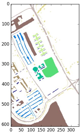
Remote Sens. 2020, 12, 1257                                                                         2 of 26

      However, HSI data processing faces important memory and computational requirements,
due the large amount of information provided by EO airborne/satellite instruments. In fact,
imaging spectrometers are able to collect hundreds of images over large areas along the Earth’s surface,
gathering hundreds of narrow and continuous spectral bands along different wavelengths. As a result,
each pixel in a HSI cube measures the reflection and absorption of electromagnetic radiation from
ground objects into several spectral channels, creating a unique spectral signature for each material
optically detected by the spectrometer [5]. This allows for a very accurate characterization of land
cover surface, which is useful for the modeling and mapping of materials of interest but presents
significant computational requirements. In particular, spectral-based classification algorithms need to
process large amounts of spectral information in order to correctly assign a label (which corresponds to
a fixed land cover class) to each pixel in the HSI scene, facing heavy computation burdens [6]. In this
sense, the development of parallel implementations of traditional classification algorithms for fast and
accurate processing is a requirement in order to efficiently process large HSI data repositories through
proper management of computational resources.
      With this aim, high performance computing (HPC) has become an efficient tool, not only for
managing and analyzing the increasing amount of remotely sensed data that are currently being
collected [7–10], but also for efficiently dealing with the high dimensionality of HSI data cubes [11,12].
From a computational point of view, most spectral-based HSI data classification algorithms exhibit
inherent parallelism at three different levels [13]:

•     through HSI pixel vectors (coarse-grained pixel level parallelism),
•     through spectral-band information (fine-grained spectral level parallelism), and
•     through tasks (task-level parallelism).

      HSI classification algorithms generally map nicely on HPC systems [14], with several HPC
approaches (from coarse-grained and fine-grained parallelism techniques to complex distributed
environments) already successfully implemented. For instance, distributed approaches based on
commodity (homogeneous and heterogeneous) clusters [15,16], grid computing [17,18], and cloud
computing techniques [19–22] provided good results in terms of reducing execution times, enabling an
efficient processing of massive data sets on the ground segment. However, dedicated resources such as
massively parallel clusters and networks of computers are generally expensive and hard to maintain,
being cloud computing a more appropriate and cheaper approach (in addition to a fully distributed
solution) due to its “service-oriented” computing and “pay-per-use” model [23]. Neither cluster nor
cloud computing models allow on-board processing.
      On the other hand, parallel solutions based on multicore CPUs [10,24,25], graphics processing
units (GPUs) [14,26–29], and field programmable gate arrays (FPGAs) [30–34] were also successful,
leading to near real-time performance in many HSI applications [35]. These platforms generally
provide a cheaper solution when compared to large-scale distributed systems. Also, these approaches
consume much less energy in comparison with cluster-based or distributed systems, being GPU
systems (in particular, those with low-power consumption [36]) and FPGAs the ones currently
offering the best performance/consumption ratio. Nevertheless, although both kinds of devices
are appealing for on-board processing, FPGAs (despite their reconfigurability) are still more difficult
to program than GPUs. In fact, GPUs are massively parallel programmable systems that can satisfy
the extremely high computational requirements by HSI-based applications at low cost, with very good
programmability. As a result, many HSI data processing algorithms were implemented on GPUs,
including target and anomaly detection methods [37,38], and techniques for image compression [39],
scene classification [40], and spectral unmixing [41].
      In this paper, we develop a new GPU implementation of the traditional support vector machine
(SVM) algorithm [42]. Traditionally considered to be a powerful classifier in a wide variety of fields,
such as medical computing or text and image processing (among others), the SVM has been succefully
adopted in HSI classification problems. It separates two classes of samples with the maximal margin
Remote Sens. 2020, 12, 1257 3 of 26
by exploiting an optimal decision boundary [43]. As a result, SVMs have often been found to provide
higher classification accuracies than other widely used pattern recognition techniques, such as
the maximum likelihood, the random forest (RF) or the multi-layer perceptron (MLP) classifiers.
Furthermore, SVMs appear to be particularly advantageous in heterogeneous environments, for which
only a few training samples are available per class. The SVM has demonstrated its success in HSI data
classification in a multitude of scientific works within the remote sensing field [44] due to its robust
behaviour when dealing with high-dimensional data and its great ability to generalize to unseen data.
However, SVMs exhibit a high computational cost, which strongly discourages its use when facing
large-scale, real-time HSI classification problems.
To mitigate the aforementioned problem, several techniques were adopted to reduce the execution
time of SVMs. For instance, in [45], Osuna et al. presented a decomposition algorithm by addressing
sub-problems iteratively to enable tackling larger problems. In [46], Platt proposed the sequential
minimal optimization (SMO) algorithm by decomposing the quadratic programming (QP) problem
into a series of smaller QP subproblems that can be solved analytically, without the need for a
time-consuming QP optimization. Ease of implementation is a typical feature of the SMO algorithm.
In [47], Fan et al. developed a series of working set selection (WSS) heuristics, based on second
order information, to achieve a faster convergence of the SMO. Recently, some researchers used the
portability and excellent computing performance of GPUs to address the computational requirements
of SVMs. In particular, Tan et al. [48] proposed a novel two-level parallel computing framework based
on NVIDIA’s compute device unified architecture (CUDA) and OpenMP to accelerate SVM-based
classification, while Li et al. [49] used GPU devices to improve the speed performance of SVM training
and prediction stages.
In this work, we present a novel GPU implementation of SVMs that does not only reduces
the execution time by massively parallelizing the operations of the algorithm on the GPU,
but also performing efficient memory management during data-reading and writing operations [50].
We empirically evaluate the efficiency of our method considering different HSI real scenes,
which comprise urban and agricultural land-cover information, and observed that it is able to
maintain the precision in the results while significantly improving the computational performance.
The remainder of the paper is organized as follows. Section 2 presents the fundamentals
of the SVM method adapted to HSI data. Section 3 describes the GPU implementation of the
considered classifier. Section 4 validates the GPU implementation by comparing it with other existing
implementations. Finally, Section 5 concludes the paper with some remarks and hints at plausible
future research lines.
2. Support Vector Machines (SVMs): A Review
2.1. Linear SVM
Any HSI classification method y = f (x) can be described as the mapping function f : Nnb → N,
where the domain is composed by those spectral pixels xi ∈ Nnb = [ xi1 , xi2 , · · · , xinb ] that encode the
reflectance values of the HSI cube X ∈ Nnh ×nw ×nb , which is composed by nh · nw pixels (note that
i = {1, · · · , nh · nw }) with nb spectral bands, while the co-domain is composed by the corresponding
label-vectors yi ∈ [1, 2, · · · , nc ], being nc the number of different land cover categories. The final goal
n ·n
is to obtain the sample-label pairs for each HSI image element, {xi , yi }i=h 1 w , obtaining as a result the
final classification map Y ∈ Nnh ×nw .
In this context, the original SVM method [51] was proposed for binary classification problems,
i.e., nc = 2 so yi ∈ {1, −1}, ∀i ∈ {1, · · · , nh · nw }, where the two considered classes are linearly
separable, with at least one hyperplane separating them (see Figure 1). This hyperplane is defined
by its normal vector w ∈ Rnb and the bias b ∈ R that defines the distance between the samples and the
hyperplane. In this regard, the classifier can be defined as the discriminant function:
f (x) = wx + b, (1)Remote Sens. 2020, 12, 1257 4 of 26
where f (x) = 0 is the hyperplane and the samples lie on the planes f (x) = ±1 depending on the
class they belong to. Both parameters w and b are estimated by the SVM during the training stage in
order to maximize the distance between the closest sample and the hyperplane, i.e., with the aim of
maximizing the margin m = 2/||w|| [42]. This maximization problem should be conveniently replaced
by the equivalent minimization problem 12 ||w||2 . In the end, the SVM finds the optimal hyperplane
along the space of samples by minimizing the quadratic optimization problem given by Equation (2):
1
min ||w||2 , subject to yi (w · xi + b) − 1 ≥ 0 ∀i ∈ {1, · · · , nt } (2)
w,b 2
where nt is the number of training samples, xi is the i-th sample, and yi is the correct output
provided by the SVM, i.e., +1 for positive samples and -1 for negative ones. Considering the
Lagrangian formulation [52], Equation (2) can be simplified by replacing the inequality ≥through a
dual problem. In particular, employing the Lagrange multipliers αi ≥ 0 ∀i ∈ {1, · · · , nt }, we define the
optimization problem given by Equation (3), which only depends on the set of Lagrange multipliers
α = { α1 , α2 , · · · , α n t }:
1 nt nt nt nt
∑ ∑ yi y j xi · x j αi α j − ∑ αi , subject to αi ≥ 0 and ∑ yi αi = 0
min ∀i ∈ {1, · · · , nt }, (3)
α 2 i =1 j =1 i =1 i =1
where xi and x j are two samples of the training set with labels yi and y j and Lagrange multipliers αi and
α j , respectively. Equation (3) can be computed using QP methods, such as the SMO [53], which breaks
the problem into a series of smallest and equivalent QP problems, solving each one analytically.
Figure 1. General SVM scheme. The final goal is to approximate parameters w and b with the aim of
defining the optimal hyperplane that maximizes the margin between the two classes.
With this problem representation, the normal vector w can be derived as the sum of all the samples
that belong to the training set and modified by their corresponding Lagrange multiplier together with
nt
the associated class of the sample, w = ∑ αi yi xi , while the bias is obtained for some multiplier α j > 0
i =1
as b = wx j − y j . Moreover, the discriminant function f (x) provided by Equation (1) can be solely
described in terms of Lagrange multipliers and samples as:
nt
f (x) = ∑ αi yi ( xi · x ) + b (4)
i =1Remote Sens. 2020, 12, 1257 5 of 26
It is worth noting that each Lagrange multiplier αi measures the relevance of the sample xi when
calculating the hyperplane and classifying the data, so that samples with αi = 0 will be ignored,
while samples with αi > 0 will be considered to be support vectors. Also, from Equation (4), we
can observe that, to perform the classification of any sample x, a significant volume of memory
will be required, consuming also a large amount of computational resources to compute the dot
products needed.
2.2. Linear SVM for Linearly Nonseparable Data Classification
The linear SVM has a limitation: with linearly nonseparable data classification there may not be
a hyperplane, so the solution becomes infinite. To overcome this drawback, the linear soft-margin
SVM implements a new cost function, which takes into account the original margin maximization and
including a loss term that penalizes misclassified data, as it can be observed in Equation (5):
nt
1
min ||w||2 + C ∑ δi , subject to yi (w · xi + b) − 1 + δi ≥ 0 and δi ≥ 0, (5)
w,b 2 i =1
where δi ≥ 0 are some slack variables that are introduced into the inequality restriction yi (w · xi + b) −
1 + δi ≥ 0 to relax the condition that all the samples that belongs to the same class lie on the same side
nt
of the hyperplane. Thus, ∑ δi can be interpreted as some measure of the amount of misclassifications.
i =1
Also, a regularization constant C ∈ [0, ∞) is included to control the weight of minimizing 12 ||w||2 while
penalizing solutions with very large δi . In fact, C can be considered to be a parameter that adjusts the
robustness or flexibility of the model, depending its value.
Once more, the Lagrangian formulation can be applied to translate the primal problem defined
by Equation (5) into the dual problem of Equation (3), by simply introducing the box constraint
C ≥ αi ≥ 0. The slack variables δi do not affect the optimization problem.
2.3. Kernel SVM for Non-Linear Data Classification
As an alternative to the soft-margin implementation, the SVM method can be adapted to perform
non-linear classification by including a kernel [54,55] within the classifier. The main idea is to map the
original feature vectors xi ∈ Nnb into a higher dimensional Euclidean space, denoted as H, by using a
non-linear vector function Φ : Nnb → H, as we can observe in Figure 2. In this context, the optimal
margin problem can be posed in the space H by replacing the original inner product between the
samples xi · x with the transformed vectors Φ(xi ) · Φ(x), so the discriminant function will be defined as:
nt
f (x) = ∑ αi yi (Φ(xi ) · Φ(x)) + b
i =1
nt
(6)
Replacing K (xi , x) = Φ(xi ) · Φ(x) → f (x) = ∑ αi yi K ( xi , x ) + b
i =1
Equation (6) can be easily simplified by assuming there is such a kernel function that K (xi , x) =
Φ(xi ) · Φ(x). This assumption allows avoiding the computation of the inner product between
transformed vectors, significantly reducing the computational consumption of the algorithm. To ensure
the existence of the underlying map Φ, the kernel function is positively defined [51] by satisfying
Mercer’s conditions [56].
Finally, the solution of the dual problem can be also meaningfully simplified as:
1 nt nt nt nt
∑ ∑ yi y j K xi x j αi α j − ∑ αi , subject to C ≥ αi ≥ 0 and ∑ yi αi = 0
min (7)
α 2 i =1 j =1 i =1 i =1Remote Sens. 2020, 12, 1257 6 of 26
Figure 2. In order to deal with non-linearly separable data, the SVM applies a transformation Φ to
translate the data from the original non-linear representation in space Nnb , to a linear representation in
space H, i.e., Φ : Nnb → H.
In fact, the kernel function usually measures the distance between the input sample xi and the
other training samples x j . Table 1 shows some of the most widely used kernels. In particular, the RBF
kernel has quite interesting properties. It can be simplified as exp −γ||xi − x j ||2 , where γ controls
the model’s performance, in the sense that a small value of γ will provide classification solutions with
low bias and high variance, while a high value of γ will give solutions with high bias and low variance.
Table 1. Most common kernels in the SVM method, where xi and x j are two samples of dataset X.
Linear h xi , x j i
Polynomial ( γ h xi , x j i + c )n
Gaussian exp(−γ||xi − x j ||2 )γ
Sigmoid tanh (γhxi , x j i +c)n
||xi −x j ||2
Radial basis function (RBF) exp − 2σ2
2.4. Multi-Class SVM
The aforementioned SVM implementations can be generalized to develop multi-class classification
by combining several binary classifiers [42]. In this regard, there are two main strategies that can
be adopted to perform multi-class classification [57]: (i) constructing and combining several binary
classifiers, and (ii) considering all data in one optimization formulation.
Regarding the first approach, it is usual to find one-against-all, one-against-one and decision directed
acyclic graph (DDAG)-based approaches for multi-class SVM in the available literature [58–60]. The first
approach constructs nc pairwise classifiers, where the k-th model is trained with those samples that
belong to the k-th class by assigning them a positive label (while the rest of the samples are paired
with negative labels). The classification procedure applies the nc SVM models to each sample xi ,
selecting the label of the classifier f k (x) with the largest margin:
yi = arg max f k (xi ) (8)
k
As a result, nc nt -variable QP-problems have to be solved, which implies that training time
scales linearly with nc . Instead of developing nc classifiers, the one-against-one approach adopts a
pairwise decomposition strategy, implementing nc (nc − 1)/2 binary models on all pairs of training
data. Each model f kt is trained on data that belong to two different classes, k and t, ignoring all the
other classes. In this way, those samples that belong to class k are labeled as positive, while the samplesRemote Sens. 2020, 12, 1257 7 of 26
that belong to class t correspond to the negative label (note that f tk = − f kt ). The final label is selected
by majority voting strategy: !
yi = arg max
k
∑ f kt (xi ) (9)
t
It is noteworthy that the one-against-one approach exhibits a much more robust behaviour
when classifying imbalanced datasets; however, it is also more computationally expensive than the
one-against-all for simpler problems, such as those with fewer classes.
Finally, the DDAGSVM also solves nc (nc − 1)/2 binary models during the training stage,
implementing a rooted binary directed acyclic graph with also nc (nc − 1)/2 internal nodes (each
one is a binary SVM) and nc leaves (i.e., the predicted class) during the testing stage.
3. GPU-Accelerated SVM for HSI Data Classification
3.1. Previous Works and Proposal Overview
Despite obtaining great accuracy results, the training and prediction steps of the SVM algorithm
are very expensive from a computational point of view, especially for large and complex problems.
Furthermore, it is noteworthy that kernel-based techniques can greatly simplify the computations,
thus reducing the execution times. However, these methods need to use all the data to properly
calculate the kernel, which generally requires large memory consumption [61]. In particular, HSI data
offers a great challenge to the SVM classifier, mainly due to (both) the large spectral dimensionality and
volume of data to be processed. As noted in Section 1, there were some previous works in the literature
focused on optimizing and parallelizing the execution of the SVM. However, there are few efforts in the
recent literature oriented at the exploitation of GPU-based implementations for HSI data classification.
From the current state-of-the-art in the literature, we can highlight two works. Tan et al. [48]
combined the NVIDIA Compute Unified Device Architecture (CUDA) [50] and OpenMP [62] to
optimize the classification problem, and implemented as a multi-class SVM following one-against-one
strategy. In this sense, they were able to run the one-against-one strategy in parallel by implementing
an OpenMP-based approach, while each single WSS-based binary SVM classifier was parallelized into
GPUs. In addition, the calculation of every kernel element K (xi , x j ) was done by the GPU, being the
constant values stored into the shared memory of the GPU device, following column-major order,
and sent (when needed) through a broadcasting mechanism. Also, Wu et al. [63] developed a
GPU-parallelized SVM method based on composite kernels (SVMCK) [64] and able to integrate spatial
and spectral information, with the aim of improving the accuracy in HSI data classification tasks.
In this context, they carried the calculations of the composite kernel matrix in the GPU. The resulting
K (xi , x j ) were copied to the host (CPU), and then stored in the available memory of the host. The rest
of the computations were carried out in the CPU.
In this context, we propose a new parallel version of the SVM algorithm for high dimensionality
data. Our proposal can be efficiently generalized to be applied in other fields, being our parallel
SVM adapted to the specific case of remote sensing HSI data classification. In particular, we propose
a parallel implementation of a multi-class SVM, following one-against-one strategy, with the RBF
kernel. It must be noted that each single binary SVM has been solved through the SMO method.
Furthermore, the SMO solver (during the training stage) and the full inference stage were paralleled
into a general purpose GPU (GPGPU) framework, employing the NVIDIA CUDA platform. Our goal is
not only to achieve a good speed up ratio in comparison with other traditional SVM implementations,
but also to develop a scalable implementation with regards to both the amount of data and the
spectral dimensionality of the data. In this regard, the implemented approach performs the algorithmic
parallelization of the SVM operations during the training and inference stages, implementing at the
same time a series of optimizations in the memory read and write operations, with the aim of reducing
the number of communications between the host and the device, and to reduce the memory latency.
Also, it should be noted that a data-oriented parallelization strategy has been adopted, parallelizing theRemote Sens. 2020, 12, 1257 8 of 26
operations related to data management and reusing as much information as possible between different
iterations. Regarding to this, a batch-based approach has been implemented within the SMO with the
aim of solving multiple sub-problems in parallel. Particular attention has been paid to the calculation
of the kernel matrix, as it consumes a massive amount of computational and storage resources. In the
following sections we will provide details about our new implementation.
3.2. CUDA Platform
To obtain an accelerated version of the SVM for HSI data classification, a GPGPU-based
implementation has been employed using NVIDIA CUDA platform [50]. The main goal is to exploit
the full computing power of GPU devices (using the general-purpose parallel computing platform
and the programming model offered by CUDA) to solve many complex computational problems
in a more efficient way. Specifically, we solve nc binary SVM instances (with the RBF kernel) that
compose our multi-class SVM algorithm for remote sensing HSI data classification. In this context,
we consider the GPU device as a set of stream multiprocessors, composed by several cores with
a 3-level hierarchical memory system: (i) several fast registers that are accessible by each stream
processor, (ii) a multiprocessor-level memory that is shared between all the cores that compose the
multiprocessor, and (iii) a global memory shared between all the multiprocessors.
As we can observe in Figure 3, CUDA maintains the hierarchy of memories at the same time
that provides a programming model which abstracts the system of cores and multiprocessors into
a three-level logical representation of threads, blocks and grids, where the thread is the minimum
processing unit (that can be grouped into 1D/2D/3D blocks of warps), and the blocks can be
organized into a 1D/2D grid environment. In this sense, the programmer determines the logical
representation by organizing the structure of the threads in the grid that best fits the data structure
handled by the problem to be parallelized. Underneath, CUDA maps this representation to the actual
hardware resources. This distinction between physical and logical representations allows CUDA-based
algorithms to be ported to any NVIDIA GPU platform, improving their scalability and computing
performance as new and higher-capacity GPUs are released to the market. In addition, it should be
highlighted that each thread has access to three different memory spaces: its local memory, the memory
shared by all the threads of the same block, and the global memory shared by all the threads of the
grid. Therefore the correct handling of the threads and their accesses to memory are fundamental for
the correct and optimal parallelization of the problem.
Figure 3. Programming and memory model provided by NVIDIA CUDA for a GPU device.Remote Sens. 2020, 12, 1257 9 of 26
Through the organization and synchronization of the threads, we can develop the parallel
processing of the operations carried out by the SVM method. In particular, we can differentiate
between those operations performed during the training stage of the SVM and those operations
performed during the inference step.
3.3. Parallel SMO during the Training Stage
3.3.1. Previous Concepts about the SMO Algorithm
As pointed out before, we adopted the one-against-one approach for the multi-class SVM to
perform remote sensing HSI data classification. Therefore nc (nc − 1)/2 binary models must be
properly trained to extract the support vectors and derive the corresponding Lagrange multipliers for
each classifier. In particular, the binary models were trained using a decomposition method to solve
the convex optimization problem defined by Equation (7). It is noticeable that the main difficulty when
solving Equation (7) is how to calculate the kernel matrix K ∈ Rnt ×nt that stores the kernel values
K (xi , x j ), ∀i ∈ [1, nt ] and ∀ j ∈ [1, nt ], as:
K ( x1 , x1 ) K ( x1 , x2 ) ··· K ( x1 , x n t )
K ( x2 , x1 )
K ( x2 , x2 ) ··· K ( x2 , x n t )
K= .. .. .. ..
. . . .
K ( x n t , x1 ) K ( x n t , x2 ) ··· K ( xnt , xnt )
Usually, K is a dense matrix and may be too difficult to be efficiently stored and handled if nt is
too large. To deal with this limitation, some decomposition methods were designed [46,47,65–74] to
break down the problem into several smaller and easier to handle sub-problems, where small subsets
of Lagrange variables α are modified by employing some columns of K instead of the entire matrix.
In particular, the SMO [46] algorithm has been considered in this work.
The SMO is a simple and iterative algorithm that allows for the quick and effective resolution
of very large QP problems (such as those involved in the SVM calculations) by decomposing such
overall QP problem into smaller QP sub-problems [45], which are solved analytically without the need
for numerical optimization. It solves the optimization problem described by Equations (3) and (7),
by solving the smallest possible optimization problem at every step until the optimal condition of
nt
the SVM classifier is reached. As the linear equality constraint ∑ yi αi = 0 involves the Lagrange
i =1
multipliers αi , the smallest possible optimization problem will involve two such multipliers, in the
sense that, if we change one αt by an amount in either direction, then the same change must be applied
to another αl in the opposite direction. That is, αt and αl should be on the same line in order to maintain
the constraint (see Figure 4):
yt αt + yl αl = yt α̂t + yl α̂l , subject to αt ≥ 0 and αl ≥ C (10)
In this way, the SMO algorithm comprises two main components: (i) a heuristic for selecting the
pair of Lagrange multipliers to be optimized, and (ii) an analytic method for solving those multipliers.
In this sense, in each iteration the SMO algorithm heuristically chooses two Lagrange multipliers αt
and αl at every step to jointly optimize, then it analytically obtains the new optimal values α̂t and α̂l ,
and finally it updates the SVM to reflect the new values.Remote Sens. 2020, 12, 1257 10 of 26
Figure 4. The inequality constraint C ≥ αi ≥ 0 forces the Lagrange multipliers to be into a box while
nt
the linear equality constraint ∑ yi αi = 0 forces them to lie on a diagonal line. Therefore, one step of
i =1
the SMO algorithm should find the optimum values α̂t and α̂l on a diagonal line segment.
Focusing on the heuristic procedure, the SMO applies two heuristic searches, one for each
Lagrange multiplier. The first multiplier αt is chosen by iterating over the entire training set, looking for
those samples that violate the Karush-Kuhn-Tucker (KKT) conditions [75] that help to find an optimal
separating hyperplane. In particular, the KKT conditions for Equation (7) are:
αi = 0 ⇔ yi (wxi + b) ≥ 1,
C > αi < 0 ⇔ yi (wxi + b) = 1, (11)
αi = C ⇔ yi (wxi + b) ≤ 1
where yi is the correct SVM output and (wxi + b) is the current output of the SVM for the i-th sample
xi , ∀i ∈ [1, nt ]. Any αi that satisfies the KKT conditions will be an optimal solution for the QP
optimization problem defined by Equation (7). On the contrary, any αi that violates the KKT conditions
will be eligible for optimization, so the SMO’s goal is to iterate until all these conditions are satisfied
within a tolerance threshold (in our case, this tolerance has been set to 0.001). Once the first αt has
been chosen, the second Lagrange multiplier αl is selected in order to maximize the size of the step
taken during joint optimization. To do this, the SMO method implements an optimality indicator
vector E = [ E1 , E2 , · · · , Ent ], where each Ej is the optimality indicator of the j-th training sample, i.e.,
the classification errors on the j-th sample:
!
nt
Ej = f (x j ) − y j = ∑ αi yi K ( xi , x j ) + b − yj (12)
i =1
Related to this, αt and αl can be selected by looking for those samples xt and xl that have the
maximum and minimum optimality indicators that maximize | Et − El |, so if Et is positive, the SMO
will choose a sample with minimum El , while if Et is negative, the SMO will select a sample with
maximum El . The desired indexes t and l can be directly obtained by computing Equation (13) [67]:
t = arg min{ Ei |xi ∈ Xupper }
i
( Et − Ei )2
(13)
l = arg max | Et < Ei , xi ∈ Xlower
i µiRemote Sens. 2020, 12, 1257 11 of 26
where µi = K (xt , xt ) + K (xi , xi ) − 2K (xt , xi ), Et and Ei are the optimality indicator of samples xt and xi ,
respectively, and Xupper = X1 ∪ X2 ∪ X3 and Xlower = X1 ∪ X4 ∪ X5 are two data subsets, where each
X∗ is composed by the following training samples:
X1 = {xi |xi ∈ X, 0 < αi < C }
X2 = {xi |xi ∈ X, yi = +1, αi = 0}
X3 = {xi |xi ∈ X, yi = −1, αi = C }
X4 = {xi |xi ∈ X, yi = +1, αi = C }
X5 = {xi |xi ∈ X, yi = −1, αi = 0}
Once both Lagrange multipliers have been obtained, the SMO method will compute their optimal
values α̂t and α̂l with the aim of obtaining the optimal class-separating hyperplane. In particular,
it begins by calculating α̂l , whose feasible values are framed into the constraint U ≤ α̂l ≤ V to meet
the original C ≥ αl ≥ 0, being U and V two boundaries defined as:
(
U = max{0, αl − αt }
If yt 6= yl (14)
V = min{C, C − αt + αl }
(
U = max{0, αt + αl − C }
If yt = yl (15)
V = min{C, αt + αl }
Besides, the optimal α̂l value within the range [U, V ] will be obtained as:
V,
if α̃l > V
yl ( Et − El )
α̂l = α̃ j , if V ≥ α̃l ≥ U being α̃l = αl + (16)
µ
U, if α̃l < U
where µ = K (xt , xt ) + K (xl , xl ) − 2K (xt , xl ) and Et and El are the classification errors on the t-th and
l-th training samples respectively. Once α̂l has been obtained, an optimal α̂t is easily calculated as:
α̂t = αt + yt yl (αl − α̂l ) (17)
Once α̂t and α̂l have been obtained, the SMO updates the bias threshold b such that the KKT
conditions are satisfied for the t-th and l-th samples. In this sense, three cases can occur, as we can
observe in Equation (18):
b̂1
if C > αt > 0
b̂ = b̂2 if C > αl > 0 (18)
(b̂1 +b̂2 )
otherwise
2
where b̂1 and b̂2 are defined as follows:
b̂1 = b − Et − yt (α̂t − αt )K (xt , xt ) − yl (α̂l − αl )K (xt , xl )
b̂2 = b − El − yt (α̂t − αt )K (xt , xl ) − yl (α̂l − αl )K (xl , xl )
Finally, the SMO updates the SVM. For each training sample xi , the SMO updates its Ei using the
following Equation (19):
Ei = Ei + (α̂t − αt )yt K (xt , xi ) + (α̂l )yl K (xl , xi ) (19)
The full procedure is repeated until the optimal condition is reached, i.e., Et ≥ Emax , where Emax
acts as a threshold, Emax = max{ Ei |xi ∈ Xlower }.Remote Sens. 2020, 12, 1257 12 of 26
3.3.2. CUDA Optimization of SMO Algorithm
The SVM starts by dividing the HSI scene into training and inference subsets. We can consider the
training set as a collection of instances and their associated labels, i.e., Dtrain = {X, Y}. The training
instances are represented by a 2D-matrix X ∈ Nnt ×nb composed by nt training vectors, where each
xi ∈ Nnb = [ xi,1 , xi,2 , . . . , xi,nb ] comprises nb spectral bands, while the training labels are stored into
the matrix Y ∈ Nnt ×nc , being yi = [yi,1 , yi,2 , . . . , yi,nc ] the corresponding label of sample xi in one-hot
encoding, where nc indicates the number of different land cover classes. The training stage starts by
creating the different single binary SVMs in a sequential way, confronting each class i to each different
class j, ∀i, j ∈ [1, nc ]. Each binary SVM was optimized by employing a parallel SMO solver.
The parallel SMO solver begins by creating its working set B. Traditionally, B is of size two;
however, our proposal implements a bigger working set to solve in parallel multiple subproblems of
SMO in a batch. Moreover, the proposed implementation precomputes all the kernel values for the
current working set, storing them as a data buffer on the device’s global memory, in order to reduce
the high latency memory accesses and also to avoid a large number of small read/write operations in
the CPU memory. This implies that in each iteration of the SMO algorithm, the current working batch
B will be updated, being n B Lagrange multipliers optimized. This allows us to compute (at once) n B
rows of the kernel matrix K, performing a more efficient use of the GPU by reducing the number of
accesses to the device’s global memory (which is much slower than the shared memory) and enabling
the re-use of kernel information (which in turn, reduces repeated kernel value computations). Taking
this into account, our parallel SMO solver can be divided into three different steps.
During the step 1, the parallel SMO solver looks for the n B extreme training instances which can
potentially improve the SVM the most according to Equation (9). This is parallelized by applying
consecutive parallel reductions [76] over the training samples. For each working set, the optimality
indicators of the training samples are sorted in ascending order, selecting the first n B /2 and the last
n B /2 training samples to optimize the corresponding n B Lagrangre multipliers. During the reduction,
one thread per sample takes the data from the global device memory to the block shared memory (in a
coalesced way) to perform a fast execution. It must be noted that shared memory is around 7 times
faster than global memory. Once synchronized, the threads operates over the data, where each one
takes and compares the optimality indicators of the samples from the batch, choosing the smaller or the
larger one depending on the desired Lagrange multiplier through the application of the corresponding
heuristics given by Equation (13).
Once the n B Lagrange multipliers have been selected, the improvements of the Lagrangian
multiplier pair αt and αl are sequentially obtained by one GPU thread per pair (step 2). It is worth
noting from previous Equations (13), (16) and (19) that, during training stage, the same kernel values
may be used in indifferent iterations. This implies that some kernel values can be stored into the GPU
memory with the aim of reducing the high latency memory and avoiding a large number of small
read/write operations from the CPU memory. In this sense, all the kernel values related to the n B
Lagrange multipliers are obtained, computing n B rows of the kernel matrix K through parallel matrix
multiplications [77,78]:
K ( x1 , x1 ) K ( x1 , x2 ) ··· K ( x1 , x n t )
( x2 , x1 )
K K ( x2 , x2 ) ··· K ( x2 , x n t )
KB = .. .. .. ..
. . . .
K ( x n B , x1 ) K ( x n B , x2 ) ··· K ( xn B , xnt )
In particular, the RBF-based K B matrix is computed in parallel by the GPU and stored into the
device’s global memory. Algorithm 1 provides the pseudo-code of the parallel kernel RBF function,
which were implemented following the approximate RBF kernel form:
K (xi , x j ) = exp −γ k xi − x j k2 = exp −γ k xi k2 + k x j k2 −2xi x j (20)Remote Sens. 2020, 12, 1257 13 of 26
In this context, the input parameters xx and x2x contain the ||xi ||2 , ∀i ∈ [1, . . . , n B ] and xi x j ,
∀i, j ∈ [1, . . . , n B ] values respectively, which were previously computed through parallel matrix
multiplications [78]. Then, n B threads compute the desired n B rows of the kernel matrix K B :
Algorithm 1 Parallel Kernel RBF for HSI classification
Require: xx matrix of ||xi ||2 values,
x2x matrix of xi x j values,
K B resulting kernel matrix,
n B number of rows,
nt number of training samples.
i = blockIdx.x ∗ blockDim.x + threadIdx.x
if idx < n B then
j=0
while j < nt do
K B [i, j] = exp(−γ( xx [i ] + xx [ j] − 2 ∗ x2x [i, j]))
j++
end while
end if
During the training stage, the kernel values are extracted from the global memory and gathered
into the shared memory as they are needed, avoiding repeated computations.
Finally, the parallel SMO solver updates the optimality indicator vector E of the training instances
by launching nt GPU threads that compute Equation (14) in parallel (step 3).
These training steps are sequentially repeated until the optimality condition is met or when the
SVM classifier is not able to improve.
3.4. Parallel Classification during the Inference Stage
The proposed one-against-all SVM for HSI remote sensing data multi-class classification provides
the corresponding label yi of a given test sample xi by applying Equation (8) during the inference stage.
In this sense, Equation (8) is computed in parallel, making use of the kernel values in K to reduce the
latency memory and avoid the repeated computations. Also, from Equation (6) we can observe that
K (xi , x j ) is the same that K (x j , xi ), where i and j are related to the number of test samples and support
vectors, respectively. In this sense, we can reduce the number or read/copy operations into the GPU
memory following two strategies. On the one hand, if the number of test samples is larger than the
number of support vectors, we read all the rows of the kernel matrix K that correspond to the support
vectors by reading the indexes respected to j. On the other hand, if the number of support vectors is
larger than the number of test samples, those rows that correspond to the test samples will be read by
reading the indexes respected to i.
4. Experimental Results
4.1. Experimental Environment
To evaluate the performance and the benefits of the proposed parallel SVM for HSI remote sensing
data classification, several implementations of the proposed classifier were developed and tested over
two different hardware platforms:
1. Platform 1: it is composed by an Intel Core Coffee Lake Refresh i7-9750H processor, 32 GB of
DDR4 RAM with 2667 MHz, and an NVIDIA GeForce RTX 2070 with 8 GB of RAM, graphic clock
at 2100 MHz and 14,000 MHZ of memory transfer rate. It is equipped with 2304 CUDA cores.
These processors were named CPU0 and GPU0.Remote Sens. 2020, 12, 1257 14 of 26
2. Platform 2: Intel i9-9940X processor, 128 GB of DDR4 RAM with 2100 MHz, and an NVIDIA GTX
1080Ti with 11 GB of RAM, 2037 MHz of graphic clock and 11,232 MHz of memory transfer rate.
It is equipped with 3584 CUDA cores. These processors were named CPU1 and GPU1.
CPU1 will serve as the baseline for the performance comparisons that were conducted during the
experimentation due to its characteristics. Moreover, both environments use Ubuntu 18.04.3 x64 as
operating system.
4.2. Hyperspectral Datasets
Our experiments were conducted over six different and well-known HSI scenes: Indian Pines
and Big Indian Pines, Pavia University, Salinas Valley and University of Houston. Figure 5 shows the
ground truth and the number of pixels per class for each image. Below, the characteristics of each
scene are provided.
1. The first dataset is known as Indian Pines, which was collected by the Airborne Visible Infra-Red
Imaging Spectrometer (AVIRIS) [79] over the Indian Pines test site in North-western Indiana,
which is characterized by several agricultural crops and irregular forest and pasture areas. It has
145 × 145 pixels, each of which has 224 spectral reflectance bands covering the wavelengths from
400 nm to 2500 nm. We remove the bands 104–108, 150–163 and 220 (water absorption and null
bands), and keep 200 bands in our experiments. This scene has 16 different ground-truth classes
(see Figure 5).
2. Big Indian Pines is a larger version of the first dataset, which has 2678 × 614 pixels with
wavelengths ranging from 400 nm to 2500 nm. We also remove the water absorption and
null bands, retaining 200 spectral bands in our experiments. This scene has 58 ground-truth
classes (see Figure 5).
3. The third dataset is the Pavia University scene, which was collected by the Reflective Optics
Spectrographic Imaging System (ROSIS) [80] during a flight campaign over Pavia, nothern Italy.
In this sense, it is characterized by being an urban area, with areas of buildings, roads and parking
lots. In particular, the Pavia University scene has 610 × 340 pixels, and its spatial resolution
is 1.3 m. The original pavia dataset contains 115 bands in the spectral region of 0.43–0.86 µm.
We remove the water absorption bands, and retain 103 bands in our experiments. The number of
classes in this scene is 9 (see Figure 5).
4. The fourth dataset is Pavia Centre and was also gathered by ROSIS sensor. It is composed by
1096 × 1096 pixels and 102 spectral bands. This scene also has 9 ground-truth classes from an
urban area (see Figure 5).
5. The fifth dataset is Houston University [81], which was acquired by the Compact Airborne
Spectrographic Imager (CASI) sensor [82] over the Houston University campus in June 2012,
collecting spectral information from an urban area. This scene has 114 bands and 349 × 1905
pixels with wavelengths ranging from 380nm to 1050nm. It comprises 15 ground-truth classes
(see Figure 5).
6. Finally, the sixth dataset is Salinas Valley, which was also acquired by AVIRIS sensor over an
agricultural area. It has 512 ×217 pixels and covers Salinas Valley in California. We remove
the water absorption bands 108–112, 154–167 and 224, and keep 204 bands in our experiments.
This scene contains 16 classes (see Figure 5).Remote Sens. 2020, 12, 1257 15 of 26
INDIAN PINES (IP) UNIVERSITY OF PAVIA (UP) SALINAS VALLEY (SV) PAVIA CENTER (PC)
Color Land-cover type Samples Color Land-cover type Samples Color Land-cover type Samples Color Land-cover type Samples
Background 10776 Background 164624 Background 56975 Background 635488
Alfalfa 46 Asphalt 6631 Brocoli-green-weeds-1 2009 Water 65971
Corn-notill 1428 Meadows 18649 Brocoli-green-weeds-2 3726 Trees 7598
Corn-min 830 Gravel 2099 Fallow 1976 Asphalt 3090
Corn 237 Trees 3064 Fallow-rough-plow 1394 Self-Blocking Bricks 2685
Grass/Pasture 483 Painted metal sheets 1345 Fallow-smooth 2678 Bitumen 6584
Grass/Trees 730 Bare Soil 5029 Stubble 3959 Tiles 9248
Grass/pasture-mowed 28 Bitumen 1330 Celery 3579 Shadows 7287
Hay-windrowed 478 Self-Blocking Bricks 3682 Grapes-untrained 11271 Meadows 42826
Oats 20 Shadows 947 Soil-vinyard-develop 6203 Bare Soil 2863
Soybeans-notill 972 Corn-senesced-green-weeds 3278
Soybeans-min 2455 Lettuce-romaine-4wk 1068
Soybean-clean 593 Lettuce-romaine-5wk 1927
Wheat 205 Lettuce-romaine-6wk 916
Woods 1265 Lettuce-romaine-7wk 1070
Bldg-Grass-Tree-Drives 386 Vinyard-untrained 7268
Stone-steel towers 93 Vinyard-vertical-trellis 1807
Total samples 21025 Total samples 207400 Total samples 111104 Total samples 783640
BIG INDIAN PINES SCENE (BIP)
Color Land cover type Samples Color Land cover type Samples
Background 1310047 BareSoil 57
Buildings 17195 Concrete/Asphalt 69
Corn 17783 Corn? 158
Corn-EW 514 Corn-NS 2356
Corn-CleanTill 12404 Corn-CleanTill-EW 26486
Corn-CleanTill-NS 39678 Corn-CleanTill-NS-Irrigated 800
Corn-CleanTilled-NS? 1728 Corn-MinTill 1049
Corn-MinTill-EW 5629 Corn-MinTill-NS 8862
Corn-NoTill 4381 Corn-NoTill-EW 1206
Corn-NoTill-NS 5685 Fescue 114
Grass 1147 Grass/Trees 2331
Grass/Pasture-mowed 19 Grass/Pasture 73
Grass-runway 37 Hay 1128
Hay? 2185 Hay-Alfalfa 2258
Lake 224 NotCropped 1940
Oats 1742 Oats? 335
Orchard 39 Pasture 10386
pond 102 Soybeans 9391
Soybeans? 894 Soybeans-NS 1110
Soybeans-CleanTill 5074 Soybeans-CleanTill? 2726
Soybeans-CleanTill-EW 11802 Soybeans-CleanTill-NS 10387
Soybeans-CleanTill-Drilled 2242 Soybeans-CleanTill-Weedy 543
Soybeans-Drilled 15118 Soybeans-MinTill 2667
Soybeans-MinTill-EW 1832 Soybeans-MinTill-Drilled 8098
Soybeans-MinTill-NS 4953 Soybeans-NoTill 2157
Soybeans-NoTill-EW 2533 Soybeans-NoTill-NS 929
Soybeans-NoTill-Drilled 8731 Swampy Area 583
River 3110 Trees? 580
Wheat 4979 Woods 63562
Woods? 144
Total samples 1644292
UNIVERSITY OF HOUSTON (UH)
Color Land cover type Samples train Samples test
Background 649816
Grass-healthy 198 1053
Grass-stressed 190 1064
Grass-synthetic 192 505
Tree 188 1056
Soil 186 1056
Water 182 143
Residential 196 1072
Commercial 191 1053
Road 193 1059
Highway 191 1036
Railway 181 1054
Parking-lot1 192 1041
Parking-lot2 184 285
Tennis-court 181 247
Running-track 187 473
Total samples 2832 12197
Figure 5. Number of available samples in the considered HSI datasets.Remote Sens. 2020, 12, 1257 16 of 26
4.3. Performance Evaluation
With the aim of evaluating the computational performance obtained by the proposed GPU
implementation of SVMs for HSI data classification, and making a thorough analysis of the
implemented classifiers also in terms of accuracy, several experiments were carried out:
1. The first experiment focuses on the classification accuracy obtained by our GPU
implementation as compared to a standard (CPU) implementation in LibSVM [83]. In particular,
proposed GPU-SVM was compared with its CPU counterpart, the random forest (RF) [40] and
the multinomial logistic regression (MLR) [40].
2. The second experiment focuses on the scalability and speedups achieved by the GPU
implementation with regards to the CPU implementation, from a global perspective. As we
pointed before, CPU1 will be considered to be the baseline due its characteristics that make it the
slowest device.
3. The third and last experiment focuses on some specific aspects of the GPU implementation,
including data-transfer times.
In the following, we describe in detail the results obtained in each of the aforementioned experiments.
4.3.1. Experiment 1: Accuracy Performance
In this experiment, we use the fixed training and test data for the AVIRIS Indian Pines image
[displayed in Figure 6c,d], the ROSIS Pavia University image [displayed in Figure 7c,d] and the
University of Houston image [Figure 8c,d]. These fixed training and test sets are publicly available
online from the IEEE Geoscience and Remote Sensing Society (GRSS) data and algorithm evaluation
website (DASE) at http://dase.grss-ieee.org. The main rationale for using these fixed training sets is
that all algorithms can be compared in a fair way, regardless of random splits of training and test sets.
The obtained classification results can be graphically observed in Figures 6 and 8. In particular,
Figures 6a, 7a and 8a respectively show false color compositions of the aforementioned three images,
while Figures 6b, 7b and 8b show the entire ground-truth data for each image. The results obtained
by two well-known classifiers: RF [see Figures 6e, 7e and 8e] and the multinomial logistic regression
(MLR) [see Figures 6f, 7f and 8f] are reported, together with the classification maps obtained by the
CPU (LibSVM) implementation of the SVM [see Figures 6g, 7g and 8g] and our GPU implementation
of SVM [see Figures 6h, 7h and 8h]. Although all classification maps have the typical “salt and pepper”
noise of spectral classifiers, we can see that SVM classifiers achieve a higher quality map by classifying
certain regions of the scenes more precisely, for instance the Soybeans-notill and Oats land-covers in
Indian Pines scene or the the tree-line areas of Pavia University. Moreover, those classification maps
obtained by CPU-based SVM and GPU-based SVM are quite similar.
The individual class accuracies are reported on Table 2. Also the overall (OA), average (AA)
accuracies and kappa coefficient are shown for each HSI dataset. We can observe that the CPU and
GPU implementations of the SVM classifier reach the best OA and AA percentages in all datasets,
exhibiting also the best kappa value. In particular, as shown in all cases, the OA obtained by our GPU
implementation of SVM is very similar to that obtained by the corresponding CPU implementation,
and superior to that obtained by other well-known classifiers such as RF and MLR.Remote Sens. 2020, 12, 1257 17 of 26
Table 2. Classification results obtained by different techniques for the Indian Pines, University of Pavia
and University of Houston scenes, using the fixed training and test sets available for these datasets in
http://dase.grss-ieee.org.
Indian Pines University of Pavia Houston University
Class RF MLR RF MLR RF MLR
SVM SVM SVM
[40] [40] CPU GPU [40] [40] CPU GPU [40] [40] CPU GPU
1 32.80 68.0 88.0 88.0 79.59 77.7 83.08 81.85 82.55 82.24 82.34 82.15
2 51.56 78.07 80.74 79.32 55.2 58.78 67.45 67.2 83.5 82.5 83.36 83.36
3 44.41 59.41 67.57 67.43 45.42 67.22 64.85 65.0 97.94 99.8 99.8 99.8
4 26.46 25.25 51.52 49.9 98.73 74.29 98.28 98.35 91.46 98.3 98.96 97.86
5 79.34 88.32 87.23 86.28 99.14 98.88 99.28 99.3 96.69 97.44 98.77 98.6
6 95.71 96.89 96.61 96.67 78.77 93.52 92.06 92.3 99.16 94.41 97.9 96.78
7 20.0 50.0 100.0 100.0 80.41 85.12 88.89 88.95 75.35 73.41 77.43 75.95
8 100.0 99.2 98.8 98.8 90.96 87.58 92.12 92.31 33.03 63.82 60.3 57.78
9 16.0 40.0 60.0 50.0 97.69 99.22 96.35 96.6 69.2 70.25 76.77 77.88
10 8.47 56.14 81.71 82.03 43.9 55.6 61.29 61.56
11 89.63 81.64 86.95 87.77 69.79 74.19 80.55 81.2
12 26.6 68.44 77.66 77.94 54.12 70.41 79.92 80.65
13 89.25 96.25 93.75 94.25 59.86 67.72 70.88 72.56
14 92.0 89.95 90.64 90.83 99.35 98.79 100.0 100.0
15 38.79 82.83 76.77 81.21 97.42 95.56 96.41 97.42
16 93.64 93.18 88.64 88.64
OA 65.69 78.16 84.21 84.25 70.15 72.23 78.91 78.67 72.97 78.98 81.86 81.69
AA 56.54 73.35 82.91 82.44 80.66 82.48 86.93 86.87 76.89 81.63 84.31 84.24
K(x100) 59.87 74.99 81.98 82.0 63.01 65.45 73.37 73.09 70.96 77.31 80.43 80.25
(a) False RGB (b) GT (c) Train set (d) Test set
(e) RF (65.69%) (f) MLR (78.16%) (g) SVM-CPU (84.21%) (h) SVM-GPU (84.25%)
Figure 6. Classification maps for the Indian Pines dataset with the fixed training test sets in
http://dase.grss-ieee.org. (a) False color composition. (b) Ground-truth (available labeled samples).
(c) Fixed training set. (d) Fixed test set. (e) Classification map obtained by the RF classifier.
(f) Classification map obtained by the MLR classifier. (g) Classification map obtained by the
SVM classifier (LibSVM implementation). (h) Classification map obtained by the proposed GPU
implementation. The corresponding overall classification accuracies are shown in brackets.Remote Sens. 2020, 12, 1257 18 of 26
(a) False RGB (b) GT (c) Train set (d) Test set
(e) RF (70.15%) (f) MLR (72.23%) (g) SVM-CPU (78.91%) (h) SVM-GPU (78.67%)
Figure 7. Classification maps for the Pavia University dataset with the fixed training test sets in
http://dase.grss-ieee.org. (a) False color composition. (b) Ground-truth (available labeled samples).
(c) Fixed training set. (d) Fixed test set. (e) Classification map obtained by the RF classifier.
(f) Classification map obtained by the MLR classifier. (g) Classification map obtained by the
SVM classifier (LibSVM implementation). (h) Classification map obtained by the proposed GPU
implementation. The corresponding overall classification accuracies are shown in brackets.Remote Sens. 2020, 12, 1257 19 of 26
(a) False RGB (b) GT
(c) Train set (d) Test set
(e) RF (72.97%) (f) MLR (78.98%)
(g) SVM-CPU (81.86%) (h) SVM-GPU (81.69%)
Figure 8. Classification maps for the University of Houston dataset with the fixed training test
sets in http://dase.grss-ieee.org. (a) False color composition. (b) Ground-truth (available labeled
samples). (c) Fixed training set. (d) Fixed test set. (e) Classification map obtained by the RF
classifier. (f) Classification map obtained by the MLR classifier. (g) Classification map obtained
by the SVM classifier (LibSVM implementation). (h) Classification map obtained by the proposed GPU
implementation. The corresponding overall classification accuracies are shown in brackets.
4.3.2. Experiment 2: Scalability and Speedup
In this experiment, we used randomly selected training/test sets to evaluate the scalability of our
GPU implementation as the amount of training becomes larger. In particular, 1%, 3%, 5%, 10%, 15%,
20%, 25%, 30%, 40%, 60% and 80% of training data were considered for the University of Pavia, Pavia
Center, Salinas Valley and Big Indian Pines datasets.
Figure 9 reports the processing times (and speedups) measured in the considered CPUs (CPU0
in the first hardware platform and CPU1 in the second platform) and GPUs (GPU0 in the platform 1
and GPU1 in the platform 2) as the percentage of training increases. As we can observe in Figure 9,
for all the considered images in this experiment (University of Pavia, Pavia Center, Salinas Valley
and Big Indian Pines), the processing times increase as the percentage of training samples increases.
This is expected, as the complexity of the classification problem becomes larger. However, we can
also observe that the speedups obtained become more significant with the training size, particularly
for the larger images. For instance, with University of Pavia (about 34,220 pixels when training with
80% of data) the implementation is able to reach a speedup of x6 with the fastest GPU, while with Big
Indian Pines (around 1,315,433 samples when considering 80% of training data) is x140 faster than the
baseline. This indicates that our newly developed GPU implementation of SVM scales with complexity
and problem size, which is a highly desirable feature in parallel implementations.You can also read


