A Paul Trap with Sectored Ring Electrodes for Experiments with Two-Dimensional Ion Crystals
←
→
Page content transcription
If your browser does not render page correctly, please read the page content below
A Paul Trap with Sectored Ring Electrodes for Experiments with
Two-Dimensional Ion Crystals
M.K. Ivory,1, a) A. Kato,1, b) A. Hasanzadeh,1 and B. Blinov1
University of Washington Department of Physics, Seattle , Washington, USA, 98115
(Dated: 9 April 2020)
We have developed a trapped ion system for producing two-dimensional (2D) ion crystals for applications in scalable
quantum computing, quantum simulations, and 2D crystal phase transition and defect studies. The trap is a modification
of a Paul trap with its ring electrode flattened and split into eight identical sectors, and its two endcap electrodes shaped
as truncated hollow cones for laser and imaging optics access. All ten trap electrodes can be independently DC-biased to
create various aspect ratio trap geometries. We trap and Doppler cool 2D crystals of up to 30 Ba+ ions and demonstrate
the tunability of the trapping potential both in the plane of the crystal and in the transverse direction.
arXiv:2001.05013v2 [quant-ph] 7 Apr 2020
Trapped ion qubits are one of the leading technologies for ∼150 ions have been trapped in a 2D formation in a micro-
scalable quantum computing and quantum simulations due to fabricated trap12 .
their extremely long coherence times and high-fidelity state Here, we present an experimental demonstration of a sys-
initialization, control, and readout. The linear ion trap is tem for creating 2D ion crystals as the first step toward scal-
the workhorse of trapped ion quantum computing, and has able quantum computing experiments. Our approach ad-
led to the successful demonstration on entanglement of up
to 20 qubits1 , universal quantum computation2 , and quantum
simulations3 . Proposed architectures exist that promise scal-
ing up the linear ion trap system to hundreds or even thou-
sands of qubits, such as the modular MUSIQC architecture4
and the QCCD architecture with ion shuttling5 .
2D trapped ion crystals offer a higher qubit density, and
have been proposed as a way to scale to over 100 qubits6 .
Previously, such geometries were avoided since there is only
a single point, the RF null, where micromotion can be min-
imized. Ions trapped away from the RF null inevitably ex-
perience excess micromotion that leads to the decoherence of
qubits and limits quantum gate fidelity7 . However, for trap ge-
ometries with transverse symmetry, a plane exists where there
is a node in the transverse electric field. Ion crystals in this
plane only experience excess planar micromotion, while ex-
cess transverse micromotion may be minimized. Therefore,
lasers that propagate along the transverse axis are not signif-
icantly Doppler-shifted in the ion’s frame. Unavoidable in-
plane excess micromotion causes an intensity modulation of
the laser light that interacts with the ion, but recent work out-
lines a method to compensate for this by employing a series of
segmented laser pulses8 . This method is predicted to achieve
two-qubit gates with >99.99% fidelity even between ions at
the edge of a 127-ion crystal. Applying segmented laser pulse
techniques has also recently achieved the fastest two-qubit
gates in one-dimensional trapped ion systems to date9 .
2D trapped ion crystals have been previously studied in
linear ion traps in the plane perpendicular to the trap axis,
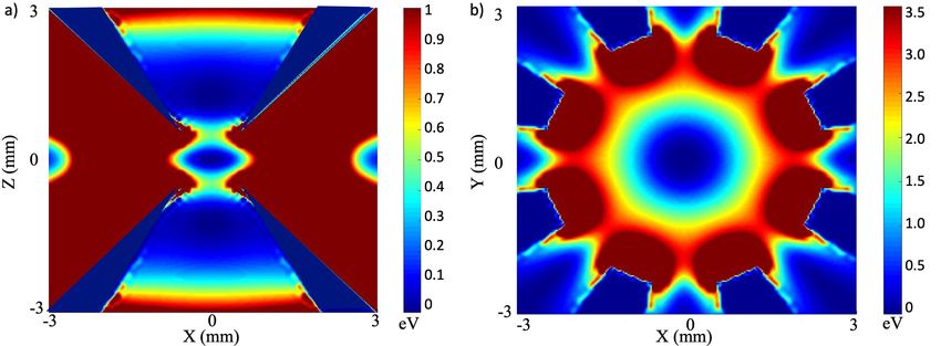
where it has been reported that 19 ions have been trapped in FIG. 1. Design and schematic layout of the trap. (a) Planar (XY)
a 2D formation10 , and indirectly observed that 34 have been cross section of the trap assembly. The eight ring electrode sectors
trapped11 . A challenge associated with linear traps is that the are shown in dark gray, and the PEEK holder in brown. In between
each ring segment, optical access tunnels allow for lasers to pass
imaging plane is not parallel to the plane of the crystal due
through. The ring sectors are spot welded to wires, which are fed
to the presence of the endcaps. It has also been reported that through wire guides. The 791 nm and 337 nm laser beams are used
for photoionization of barium, while 493 nm and 650 nm are used for
Doppler cooling the ions. (b) Photographs of the trap housed in the
PEEK structure. (c) Cross section of the trap in XZ plane. Ions are
a) Now at Sandia National Labs, Albuquerque, NM, 87185, USA imaged through one endcap, while the other is reserved for individual
b) Electronic mail: kato@uw.edu ion addressing.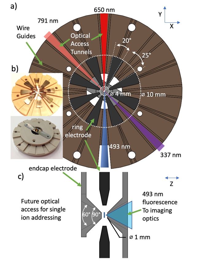
2

FIG. 2. Simulated RF pseudopotential of the trap with 1000 V of RF at 12.47 MHz. (a) XZ plane (b) XY plane. The pseudopotential is
symmetric about the Z axis and under 45°rotations in the XY plane. For these RF voltages and no DC confinement, we obtain α=2.3. We note
that a DC potential is necessary to increase the aspect ratio.

dresses two main challenges: achieving 1) the necessary as-              In addition to positioning the crystal in the center of the
pect ratios for transverse-to-planar confinement, and 2) the          trap, the ring segments may be used to change the in-plane
transverse optical access for single ion addressing and imag-         potential shape of the 2D crystal. The potential can be made
ing. We do so by employing a modified ring trap similar to            radially symmetric to make crystals with concentric rings, or
that described in a detailed study of 2D crystals for quantum         be compressed to force ions towards a line in the XY plane. As
simulations7 , using bored endcaps to allow for transverse op-        ions are compressed towards a linear shape in the XY plane,
tical access and imaging as well as strong transverse confine-        one in-plane trap secular frequency is increased while the sec-
ment. Our trap design is shown in Figure 1.                           ond is decreased. As a result α may fall below the neces-
   Our trap differs notably in several ways. The ring elec-           sary ratio and the crystal may begin to zig-zag in and out-of
trode is divided into eight sectors while each of the endcaps         plane. Ion-ion spacing can be tuned by adjusting the overall
are composed of a single piece of material. Independent DC            trap strength with the RF voltage, by adjusting α with the DC
bias voltages may be applied to each of the 10 electrodes. In         voltages, or by changing the number of ions in the crystal. We
this way we can independently tune transverse and in-plane            target spacings in the range 6.5-11 µm for single ion address-
trapping potentials. The sectors also permit in-plane optical         ing. Spacing is limited on the lower end due to the constraint
access. The trap ring sectors are 20° metal wedges with 25°           that crystals must remain planar.
spacing, with an ID of 4 mm and OD of 10 mm. The end-                    The trap components were built by the University of Wash-
caps are truncated hollow cones with a numerical aperture of          ington Physics Department Instrument Shop. The electrodes
0.5 and separation distance of 1 mm for optical access and            were Electric Discharge Machined (EDM) out of stainless
imaging from either side of the plane of the crystal.                 steel and electropolished smooth to avoid charge buildup at
   In order to achieve 2D trapped ion crystals, we estimate           burrs or edges. Kapton-insulated wires were spot welded to
the transverse (Z) to planar (XY-plane) secular frequency ratio       connect each electrode to a 10-pin vacuum feedthrough. The
α = ωz /ωr using                                                      electrodes are housed in an a machined structure composed
                              s                                       of polyetheretherketone (PEEK) that contains radial tunnels
                                  96N                                 for wire guides, laser access, and atomic beam for ion load-
                          2
                        α =               ,                   (1)     ing. The trap assembly is mounted in a 4.5” spherical octagon
                                  π 3 ω13
                                                                      vacuum chamber (Kimball Physics part no. MCF450-SphOct-
where N is the number of ions and ω1 = 1.11 is a parameter            E2A8).
below which transitions to 2D formations occur13 . While this            The system for producing, ionizing, and cooling Ba+ ions is
equation is more accurate for large ion numbers, it serves as a       similar to14 , with the notable exception that 493 nm light for
guideline of the aspect ratio necessary to produce 2D crystals        Doppler cooling is produced directly via an External Cavity
for smaller ion numbers11 . We target α > 3 to get 2D crystals        Diode Laser (ECDL) using a Sharp GH04850B2G diode. The
of ∼30 ions, according to equation 1. The numerical simula-           fluorescence of ions is imaged using an Andor iXon Electron-
tion of the trap’s RF pseudopotential with α = 2.3 is shown in        Multiplying Charge-Coupled Device (EMCCD) camera. We
Figure 2. This aspect ratio is not high enough to produce large       use a Mitutoyo 0.28 NA long working distance microscope
planar crystals, and hence the application of a DC potential to       objective lens in conjunction with a 25 mm doublet lens to im-
the endcaps is necessary.                                             age the ions, and we measure a magnification of 78x. The RF
3

FIG. 3. Trapped ion crystals produced at different trapping potentials. (a),(b),(h) begin with ∼1000 V of RF at 12.47 MHz. (a) A 29-ion
crystal. All ring sector electrodes are at -152 V with endcaps at -145 V and -150 V, a configuration found to compensate stray DC electric fields
and allow crystallization near the center of the trap. (b-g) 13 ion crystal with a voltage increase on two opposing sector electrodes, changing
the shape of the potential and crystal shape. In (f) and (g) the ions begin to zig-zag out of plane. Two opposing sector electrodes are each
increased by 15 V in 3V increments. (h-j) 6 ion crystal with increasing voltage on each endcap electrode by 5V in 2.5V increments. (k) 20 ion
crystal with reduced asymmetry. Non-fluorescing ions are other isotopes of Barium that are not addressed by the cooling laser. Image scales
are consistent in frames (b-g) and in (h-j).

voltage at 12.47 MHz is applied to the two endcap electrodes               the distance from the ion to the trap center17 . Based on the
via a helical resonator with a Q factor of ∼225. The helical               trap voltages, we estimate the scale of the planar micromo-
resonator contains 2 interwound coils that allow for each end-             tion to be 0.051 µm for every 1 µm of displacement from the
cap electrode to be DC biased independently. The RF voltage                trap center. In Figure 3(e), the distance between ions labelled
can be raised up above ∼1000 V, where it is eventually lim-                1 and 2 is approximately 54 µm. This yields an estimate of
ited by arcing in the vacuum feedthrough. Each of the 8 ring               a ∼2.8 µm of additional excess micromotion between these
electrodes are grounded for RF frequencies using RC lowpass                ions, which is in very good agreement with a measured in-
filters with cutoff frequencies of 3 MHz.                                  crease in ion image size of about 2.6 µm (1/e2 brightness)
    138 Ba+ ions are loaded into the trap at a rate of approxi-            between ions 1 and 2.
mately 1 ion/s using two-step resonant photoionization with                   In summary, we outline the design and construction of a
a 791 nm ECDL and a 337 nm nitrogen laser. We ob-                          trap for producing 2D ion crystals, and demonstrate the capa-
served 2D crystal geometries that agree with predicted shell               bility of the trap to produce such crystals with broadly tunable
structure15,16 . A selection of these crystals is shown in Figure          parameters. Future work will include characterizing micro-
3. For example, in Figure 3 (a), a 29-ion crystal is shown. For            motion in the trap and demonstrating single ion addressing
the trapping potential used to produce such crystal we mea-                for scalable quantum logic operations.
sure single ion planar secular frequencies of 203 kHz and 221                 This work was supported by the National Science Founda-
kHz through application of a tickle voltage delivered to one               tion Grant No. 1505326, University of Washington Royalty
of the ring sectors. From equation 1, we infer that the trans-             Research Fund, and the Mistletoe Fellowship. The authors
verse trap frequency is ∼600 kHz with the parameters given                 would like to thank Liudmila Zhukas, Jennifer Lilieholm, and
in Figure 2 (a). Laser-cooled crystal lifetimes of several hours           Gabriel Moreau for useful insights.
have been observed, with background collisions occasionally
(approximately once every 10 minutes) leading to dark ions
                                                                           1 N.  Friis, O. Marty, C. Maier, C. Hempel, M. Holzäpfel, P. Jurcevic, M. B.
appearing in the crystal structure or reordering of ions.
                                                                              Plenio, M. Huber, C. Roos, R. Blatt, and B. Lanyon, Phys. Rev. X 8,
    In Figure 3 we also demonstrate the tunability of our trap
                                                                              021012 (2018).
aspect ratios. In panels (b) through (g), we increase the volt-             2 D. Hanneke, J. Home, J. Jost, J. M. Amini, D. Leibfried, and D. J.
age on two opposing segments of the ring by a total of 15 V in                Wineland, Nat. Phys. 6, 13–16 (2010).
                                                                            3 P. Richerme et al., Nature 511, 198–201 (2014).
steps of 3V. The shape of the ion crystal changes from a nearly
                                                                            4 C. Monroe, R. Raussendorf, A. Ruthven, K. R. Brown, P. Maunz, L.-M.
circular in (b) to a linear crystal with in- and out-of-plane zig-
                                                                              Duan, and J. Kim, Phys. Rev. A 89, 022317 (2014).
zag in (f) and (g). The effect of increasing the endcap bias                5 D. Kielpinski, C. Monroe, and D. Wineland, Nature 417, 709–711 (2002).
voltage by 5 V in steps of 2.5 V is shown in Figure 3 (h-j).                6 D. Porras and J. I. Cirac, Phys. Rev. Lett. 96, 250501 (2006).
The ion spacing in the plane of the crystal increases as the                7 B. Yoshimura, M. Stork, D. Dadic, W. C. Campbell, and J. K. Freericks,

endcap voltage (radial confinement) is increased (decreased).                 EPJ Quantum Technology 4, 2 (2015).
                                                                            8 S. T. Wang, C. Shen, and L. M. Duan, Sci. Rep. 5, 8555 (2002).
In Figure 3(k) we show a 20 ion crystal with nearly equal pla-              9 V. Schäfer, C. J. Ballance, K. Thirumalai, L. J. Stephenson, T. G. Ballance,
nar trapping frequencies.                                                     A. M. Steane, and D. M. Lucas, Nature 555, 75–78 (2018).
    The amplitude of the excess in-plane micromotion is given              10 M. Block, A. Drakoudis, H. Leuthner, P. Seibert, and G. Werth, J. Phys. B.

by qr d/2, where qr is the radial Matthieu parameter, and d is                33, L375–L382 (2000).
4 11 K. Okada, M. Wada, T. Takayanagi, S. Ohtani, and H. A. Schuessler, Phys. Blinov, AIP Advances 4, 057124 (2014). Rev. A 81, 013420 (2010). 15 I.M. Buluta and S. Hasegawa, J. Phys. B. Atom. Molec. Phys. 42, 154004 12 B. Szymanski, R. Dubessy, B. Dubost, S. Guibal, J.-P. Likforman, and (2009). L. Guidoni, App. Phys. Lett. 100, 171110 (2012). 16 V. M. Bedanov and F. Peeters, Phys. Rev. B 49, 2667–2676 (1994). 13 D. H. E. Dubin, Phys. Rev. Lett. 71, 2753–2756 (1993). 17 C.-K. Chou, C. Auchter, J. Lilieholm, K. Smith, and B. Blinov, Rev. of Sci. 14 R. D. Graham, S.-P. Chen, T. Sakrejda, J. Wright, Z. Zhou, and B. B. Inst. 88, 086101 (2017).
You can also read