ABSTRACT Forgotten German Aeronautical and Rotating-Wing Pioneers - Royal Aeronautical ...
←
→
Page content transcription
If your browser does not render page correctly, please read the page content below
Journal of Aeronautical History                                           Paper 2021/01

                  Ludwig, Rudolf and Emil Rüb –
     Forgotten German Aeronautical and Rotating-Wing Pioneers
                                   Berend G. van der Wall
                                        Senior Scientist
                     German Aerospace Center (DLR), Braunschweig, Germany

                                        ABSTRACT

Ludwig Rudolf Rüb, a passionate inventor and enthusiastic – but mostly under-funded –
visionary lived in poverty most of his life and is virtually unknown in the rotorcraft
community. His first inventions covered combustion engines and motorcycles. Around 1900
he built a paddle-wheel plane under contract to Count Zeppelin, next he designed and built a
first version of a coaxial rotor helicopter in Munich, and then he moved to Augsburg to build a
large fixed-wing aircraft. None of these were ever finished. At the beginning of the First World
War, with support of the German army, he took up a refined version of his coaxial rotor
helicopter concept as a highly agile and maneuverable replacement of the observation balloons
used in those times, which also was intended to take an active part in warfare by installing a
machine gun or dropping bombs. It included some astonishing advanced features and, with the
help of his sons, construction was finished and ground testing started in June 1918. The end of
the war immediately stopped all work. The Treaty of Versailles demanded the destruction of
that vehicle, bringing an end to Rüb’s aeronautical work. Ludwig Rüb, a bright yet uneducated
person with good ideas, died in 1918 without having seen his rotors turning.

1.       INTRODUCTION

An inventor par excellence subordinates all other matters of life – Ludwig Rudolf Rüb (the
middle name is rarely mentioned) was given that characterization by his son Rudolf in his
unpublished life memories of 108 pages (1). Ludwig lacked proper financial background to
bring his ideas to fruition and thus he had a life with some ups and many downs, mostly in
poverty. Due to his undoubted technical talents, his persuasiveness and eloquence, Ludwig
Rüb often found sponsors funding his ideas. He never stayed long under work for hire, never
took provisions for his future, and thus mainly lived hand-to-mouth, devoted to his projects,
but not caring much for his family, until his death at age 55. This article aims at unveiling his
and his sons’ life (especially that of Rolf), with emphasis on the aeronautical inventions and
developments, especially the rotating-wing aircraft. Major sources of this article are taken
from the life memories of Rolf Rüb (1), an article in an exhibition catalogue of the Zeppelin
Museum in Friedrichshafen (2), another one by the same author (3), a book about pioneers of the
city of Ulm (4), and a booklet of the German Museum in Munich (5). The Rüb coaxial helicopter
of 1918 is mentioned in some books (6, 7), but in general the Rübs and their helicopters are

                                                  1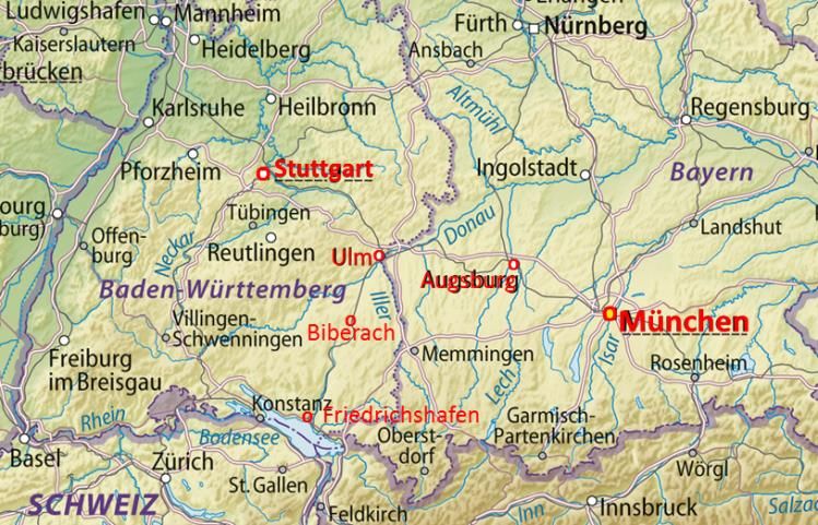
Journal of Aeronautical History                                           Paper 2021/01

unknown. This article is an edited version of a paper presented at the Vertical Flight Society’s
75th Annual Forum & Technology Display, Philadelphia, PA, USA, 13-16 May 2019 (8).

2.       THE EARLY YEARS

On May 22, 1863, Ludwig Rüb was born in Ulm on the river Danube (Donau), see Figure 1,
located in the state of Baden-Württemberg in Germany) as the oldest son of the shoemaker
Johann Martin Rüb and his wife Scharlotte Mathilda (née Geigle) (9, 10) (for unknown reason
the date of birth was officially changed to May 23 in the certificate of death (9), but police
registration (10) states May 22 and reference (11) also refers to May 23).

        Figure 1.         Map of southern Germany with major locations of Ludwig Rüb’s
                                      living highlighted in red
After a compulsory education of just eight years he was forced to learn the shoemaker’s trade,
beginning at an age of 14. It was common practice in those times to take up the parents’
profession and later to take over their business. These were the times of great progress in
industrialization, especially with the invention of combustion engines, that made Ludwig
interested in mechanics, aeronautics (ballooning was understood as aeronautics at the end of
the 19th century), motorized vehicles and motorized ships. At the age of 16 (1879) he switched
his apprenticeship to mechanics and until 1884 he learned at different workshops of mechanics,
metal machining and processing, and taught himself aeronautics by reading books on the
subject as well as technical journals. There were not many aeronautical journals available at
that time (until 1900), the most popular in German language (12-18), some others in foreign
languages, mainly in French (19-25), and in English (26-30).

                                                 2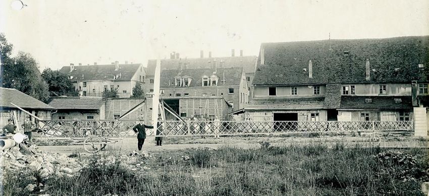
Journal of Aeronautical History                                          Paper 2021/01

In December 1884, now aged 21, Ludwig married Scharlotte Elisa Molfenter, the 18 years old
daughter of a baker’s family, whom he become acquainted with on a sports field. She had lost
her parents in early childhood and brought an inheritance of Mark 10,000 as dowry into the
marriage, a fortune at the time. One Mark (in the following abbreviated as M) was the
equivalent to 0.358 g of gold; therefore, at the time of this article M 10,000 was equivalent to
$ 153,000 or € 134,000. She gave birth to Rudolf Ludwig Rüb on 15 November 1885, and
Emil on 11 January 1890 (10), and three more children died at a very early age (11).

2.1       INVENTOR’S LIFE

This inheritance allowed Ludwig – instead of looking for a permanent job for hire – to live free
of concerns for a couple of years and to concentrate on his inventions. From 1885 on Ludwig
designed and built a gas balloon of 21 m length, 8 m diameter in the middle and 600 m³ volume
with a special large gas release valve also designed by him (“such that the balloon could not
make an attempt to escape during landing”) that later was on display in the German Museum in
Munich until destroyed during WW II. He performed several balloon ascents in different cities,
with entrance fees up to M 1 for spectators with 50% discount for military personnel and
children (Figure 2); such events were popular since at least 1872.

 Figure 2.           Advertisement for the first ascent of Ludwig Rüb’s balloon in 1889 (4)

                                                   3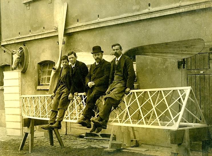
Journal of Aeronautical History                                           Paper 2021/01

But most of the thousands of spectators preferred to stay outside the fences and watched for
free, resulting in costs higher income, despite a reduced price for gas granted by the city’s
gasworks. However, they knew Ludwig’s financial situation and requested advance payment.
The trip ended in Schelklingen about 24 km away, and the balloon returned by train.

Another invention was a water-velocipede for two persons, consisting of two closed metal
tubes 1.8 m laterally separated from each other with a platform between, on which a tandem
bike frame was mounted. The chain was connected to the shaft of the water screw by a bevel
gear, while the steering was coupled with the rudder. He made a couple of demonstration rides
on rivers and lakes of southern Germany in 1885-1889 (1) and 1889 (4) which attracted some
attention, but again without commercial success.

Rüb’s assets quickly shrank as the family grew. In 1886 their home was pawned, and in May
1889 Ludwig was imprisoned for three days, because “he did not work much, rather built a
balloon and thus consumed all the fortune of his wife, such that – except for daily living –
nothing was left over.”

On 25 September 1890 they moved from Ulm to Munich (the police registration form then
reports his profession as “mechanic, shoemaker, aeronaut), where Ludwig was hired as pilot of
a captive balloon in an amusement park called “Volkspark Nymphenburg.” But income was
poor, Ludwig and his wife separated (the legal separation occurred much later in 1907 “due to
fault of the husband” (10). She, together with Emil, moved to Stuttgart to earn her own living
with sewing jobs, while Ludwig and his older son Rolf remained in Munich. Very frequent
changes of his address between 1890 and 1897 are noted in reference (10) and indicate
permanent financial problems. A second police registration form filed in 1892 lists Ludwig’s
profession as “aeronaut, mechanic, and machine-technician.”

To be free of the burden of raising his 6½ year old son Rolf (soon after he had entered school
in first grade), and to concentrate on his own interests, in 1892 Rüb gave Rolf to a troupe of
traveling entertainers/comedians. For four years Rolf toured Europe (without school education)
with these comedians and experienced all the ups and mainly downs of this unsettled life,
before coming back to his father in 1896. Rolf was then given to the family of the mechanic
Christian Haab, where Ludwig was living as tenant. Haab was working as turner at (Georg)
Krauss and (Joseph Anton von) Maffei, who at that time built locomotives; today they are as
Krauss-Maffei Wegmann GmbH & Co. an important armaments manufacturer. Then, at the
age of 10, Rolf again entered the elementary school as second-grader.

2.2       COMBUSTION ENGINES AND MOTOR CYCLES

Ludwig Rüb found work for hire in the workshop of “Hildebrand and Wolfmüller,” established
in 1879, headed by the brothers Heinrich and Wilhelm Hildebrand, Alois Wolfmüller (also an
aeronautical pioneer who had correspondence with Otto Lilienthal, bought one of his gliders
and in 1895, added a tail with rudder and elevator for steering – a standard concept of all fixed-
wing aircraft today) and Hans Geisendorf. In 1894 they built a motorcycle with a steel tube

                                                  4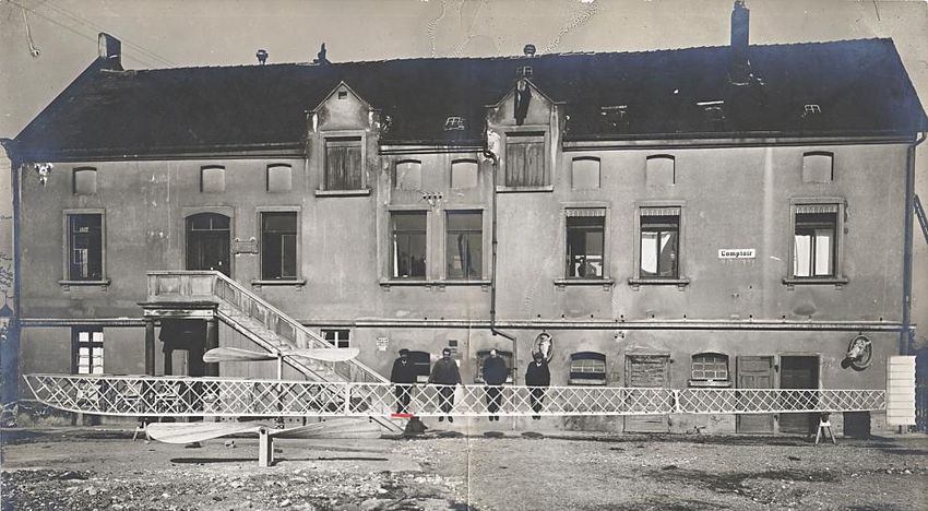
Journal of Aeronautical History                                           Paper 2021/01

frame combined with a two-cylinder combustion engine and got a patent on this vehicle the
same year (31), which formed the first mention of a motorcycle, but the company soon went
bankrupt (32).

Rüb next focused on the motorcycle and its engine design (33), and patented his inventions in
different countries (34, 35, 36). He founded Rüb & Haab and more patents were issued (37, 38, 39);
some photos can also be found in reference (40). However, continuity of developing,
marketing, waiting until serial production would start, and financial management was not
attractive for Ludwig, thus he sold his patents for some thousand Mark to Heinle and Wegelin,
left the company in 1896 for an indemnity with the ambition for new developments in
aeronautics (32). In his “Memories of Life”, his son Rolf argued that his father avoided a regular
income because he then would have been liable for support payments to his separated wife and
the other son (1).

2.3       FIRST AIRCRAFT DESIGNS

Beginning in 1896, Ludwig completely turned to the construction of light-weight combustion
engines needed for aeronautical vehicles that he was beginning to design. At this time hot air
and gas balloons were established, while steerable and motorized balloons (zeppelins) were
under construction, but “heavier than air” aircraft of all kinds were only in discussion, with
experts disagreeing which concepts would be the more successful. Fixed-wing vehicles were
favored by some, flapping wing “bird flight” was seen superior by others, and especially
rotating-wing vehicles – sometimes even with forced flapping to power them – were envisioned
by experts of the time, e.g. Eugen Kreiss in Hamburg, Germany (41), the engineer Wilhelm
Kress from Vienna, Austria (42), Georg Wellner, who was professor in Brünn, Czechia (43), and
Otto Lilienthal in Berlin (44).

Rüb, given his technical skills, the experiences with ballooning, the continuous self-study of
aeronautical literature, and his close contact with Alois Wolfmüller, was well prepared to develop
his own aeronautical vehicle, a paddle-wheel aircraft for which he obviously was inspired both
by Wellner’s patent of 1893 (45) (Figure 3a) and by Koch’s article in early 1897 (46) (Figure 3b) –
despite Lilienthal’s comments on disappointing tests performed by Wellner, published in 1895.(47)

Instead of these two concepts mentioned before, Rüb suggested just three rotating wings that
were to deliver lift and propulsion by a complicated means of pitch control during the
revolution (48, 49) (Figure 3c). He began touring German cities with lectures about his
envisaged aeronautical developments, aiming for sponsors of his ideas.

Ludwig’s formal schooling consisted of just eight years. His lack of academic training,
particularly in aerodynamic theory which was more mystery than science in those days, meant
that his main skills were mechanical rather than the numerical assessment of aerodynamics,
limiting his necessary theoretical understanding of the requirements of flight.

                                                  5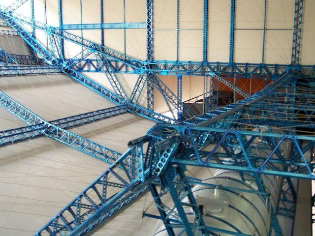
Journal of Aeronautical History                                                             Paper 2021/01

                                                                           (c)        Rüb’s concept of 1899 (48)
             (a) Wellner’s concept of 1893 (45)

Side view of the aircraft assumed in horizontal motion                     Aircraft attitude in free fall when engine inactive

                                                         Front view of the aircraft
                                       (b)      Koch’s concept of 1897 (46)
                Figure 3.         Paddle-wheel (cyclogyro) aircraft concepts in the 1890s

                                                             6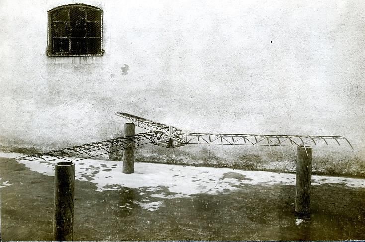
Journal of Aeronautical History                                            Paper 2021/01

In 1897 he again gave away his son Rolf, this time to Ludwig’s mother, who was living in Ulm
in poverty and hardship, which again dominated Rolf’s life. At least Rolf’s teacher offered
education for free, such that he could skip the fifth grade and leave school after the sixth grade
in 1899 at age 13. Ludwig came to the graduation and took his son back with him.

3.       FIRST AERONAUTICAL DEVELOPMENTS – LUDWIG RÜB AND
         COUNT ZEPPELIN

For ground-based vehicles, such as ships, trains, cars, motorcycles and more the weight of the
engine is of less importance than in aeronautical applications, where the weight per horse power
delivered was and still is of utmost importance. In rotating-wing applications with a much
higher power requirement for hovering compared to the power required in horizontal flight of a
fixed-wing aircraft the engine’s weight to power ratio is even more important. This problem
fascinated Rüb and prompted his combustion engine developments and their applications in
aeronautics. From 1897 he toured Germany giving lectures to disseminate his experiences and
to find sponsors for his light-weight aircraft engine and his paddle-wheel aircraft concept.

In 1898 Ludwig Rüb explained his work on a light-weight aeronautical combustion engine in a
lengthy letter to Count Zeppelin, highlighting a new ignition that would exclude any danger of
fire – a feature very important especially for Zeppelin and his dirigible motorized airships filled
with hydrogen instead of helium.(50) Rüb was initially hired by Zeppelin in 1898 as mechanic
for maintenance work and technical drawings, earning M 150 per month. The employer was
the “Gesellschaft zur Förderung der Luftschiffahrt” (Society for Promotion of Airshipping) in
Stuttgart, whose founder in 1898 was Count Zeppelin (then age 60), who also was main
shareholder with M 400,000 (50% of the total seed capital), and chairman of the supervisory
board. Tests with that engine were soon executed at the Daimler Motoren-Gesellschaft, but
with unsatisfactory results.

Rüb then asked Count Zeppelin to be permanently hired, a request supported by Zeppelin’s
engineer Hugo Kübler. In a letter to the Gesellschaft zur Förderung der Luftschiffahrt Rüb
promoted his paddle-wheel aircraft concept (51), which led to a development contract between
Count Zeppelin and Rüb on 5 July 1899. This one-page (!) contract contained 6 items (53):
1.       Construction to the best of his knowledge
2.       Costs limited to M 10,000 for building a first prototype including patent costs
3.       After a sufficient number of successful flights patenting in Germany and other
         countries
4.       50% share of profits earned by German patent revenues; 75/25% share of foreign patent
         revenues
5.       Owner is Count Zeppelin. Cancellation of the contract is justified, when the costs
         exceed M 10,000
6.       Allowance granted to the “Gesellschaft zur Förderung der Luftschiffahrt” after first
         flight to join the contract.

                                                     7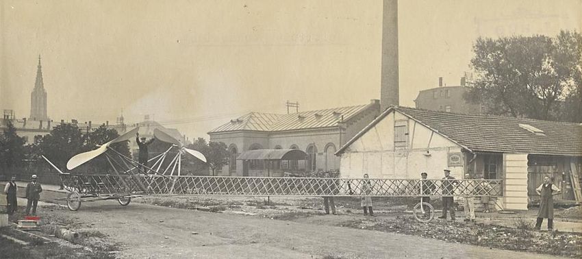
Journal of Aeronautical History                                               Paper 2021/01

The Zeppelin manufacturing site was located in Manzell near Friedrichshafen and Rüb was
given a backyard workshop in the city. Count Zeppelin, fully occupied with the development of
his dirigible airship LZ 1 (first flight in July 1900), was widely supporting heavier-than-air
aircraft as well, and the Rüb development was the first to be sponsored (2). However, he
demanded secrecy of the project – for good reason, as soon would emerge.

While Zeppelin struggled with his LZ 1, Rüb started with more detailed design and drawings,
set up his workshop, and together with his son Rolf – who had left school after the sixth grade –
began work on his aircraft, in parallel to work for Zeppelin on repair of boat motors and design
changes on a propeller test boat. Some months later Rüb began work on his paddle-wheel aircraft
(also known as cyclogyro), as shown in Figure 3c, which had two rotating shafts extending right
and left of the fuselage, to which Rüb attached three wings each. The pitch angles of these wings
were altered during one revolution via a controllable eccentric gear to adapt the lift generation to
the flight situation, as sketched in the upper part of Figure 3a.

Rolf Rüb explained this motion as equivalent to bird flight, where the wings during up- and
downstroke also change their incidence. The wing downstroke requires a negative pitch angle,
or glide angle as he called it, and the upstroke requires a positive pitch angle, or angle of attack
in his words, to simultaneously generate lift and propulsion. A heart-shaped eccentric generated
this motion by means of levers and chains. Unfortunately, no detail drawings of the mechanism,
which required pilot control, are available.

Rüb’s activities were described in a
paragraph of the illustrated chronical of Ulm
in June 1900 (52), as “A strenuous assistant
of Count Zeppelin is the shoemaker Rüb of
Ulm. Already 15 years ago (i.e. 1885) he
had taken rides in a gas balloon. Currently
he installed a workshop at Zeppelin and
began work on an airplane consisting of two
wheels with wings. He also invented a boat,
whose screw was driven by a wind wheel.”

For an exhibition of the Zeppelin Museum in
2006 a model of Rüb’s paddle-wheel aircraft
was built, shown in Figure 4, exhibiting the       Figure 4.       Model of the Rüb paddle-wheel
pitch variation between the upstroke rear                            aircraft (2)
wing and the downstroke front wing (54).

Before building the aircraft, in order to evaluate the required size of the rotating wings, Ludwig
constructed a large test apparatus to measure the performance of this concept, which required
hiring of two more mechanics with the agreement of Count Zeppelin. Around a central vertical
shaft two outriggers with the paddle-wheels could rotate in circles, each one holding a paddle-
wheel at a radius of 16 m, Figure 5.

                                                   8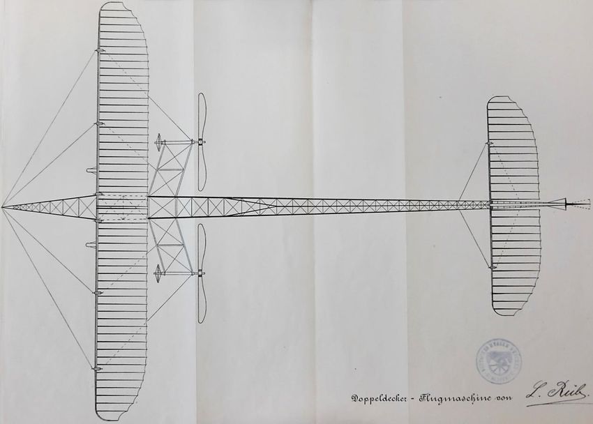
Journal of Aeronautical History                                              Paper 2021/01

The outriggers also carried a self-designed parallelogram balance for measurement of the
paddle-wheel aerodynamic performance. From that figure the wing span of one paddle-wheel
can be estimated to be 4 m, split in the center for the control mechanism. This test apparatus
was already consuming most of the contractual funds and test results were disappointing so
during 1900 to 1901 Rüb frequently requested more money from Zeppelin for continuation and
improvements, without providing encouraging results.
                                          Test rig with              one paddle-wheel

                       Figure 5.     Rüb’s paddle-wheel test apparatus (2)

Count Zeppelin was fully distracted with his own development, and – without asking for
progress of the work – obviously gave the money, until he got a new controller, Ernst Uhland,
who critically reviewed the money spent already and urged Count Zeppelin to cancel the Rüb
contract. He found that more than M 30,000 had already been spent – three times the contractual
amount – but detail drawings did not yet exist.

Zeppelin’s Chief Engineer Ludwig Dürr, who also was aware of Rüb’s disappointing tests,
supported Uhland’s demands, and finally both judged Rüb’s attempts as impossible to realize
and useless to further support, setting a deadline of 10 weeks from March 1902 to finish
ongoing work for a flight demonstration. Due to the impossibility of fulfilment Rüb
desperately offered other test methods, like downhill gliding attempts to fly with his paddle-
wheel wings like Lilienthal did, but Zeppelin now insisted on the aircraft defined in the
contract, and finally made use of the fifth clause of the contract, allowing him the cancellation
on April 4, 1902.

During these years Rolf tried different fixed-wing kites and eventually suggested to his father
to use that principle, combined with a propeller in the front, as a more promising man-carrying
attempt to fly than the paddle-wheel concept. Ludwig is reported to have rejected that proposal
with the argument that “birds also do not have a propeller at their nose.”

For Zeppelin this attempt at sponsoring aircraft development was a fiasco, with a loss of M 30,000
and without any results – only a few components of the aircraft were built and it was miles away
from being finished. To avoid bad publicity, he demanded this project should not become public.
It took until 1933, when Alfred Hildebrandt “broke the silence imposed by Count Zeppelin” and
told about the “secret Rüb project,” (5). (Hildebrandt was a German army balloon pilot, working
since 1899 on Zeppelin’s LZ 1, later author of aeronautical literature; director of the airport
Berlin-Johannisthal, he got the Wright brothers to that location in 1908.)

                                                  9
Journal of Aeronautical History                                              Paper 2021/01

It is ironic that Dürr made use of Rüb’s test apparatus paddle wheels in form of a kite that he
even demonstrated on a boat ride on Lake Constance before an illustrious audience. In this
way, Rüb’s ideas finally became airborne. However, both kites crashed into the water.

Despite disillusion over this concept it was never forgotten, and was re-investigated in the US
by Platt, US patent applied in 1927 (55); Strandgren’s cyclogyro with (disappointing) full-scale
tests at NACA reported in 1935 (56), and by the German Adolf Rohrbach (German patent from
1932 (57). The cyclogyro of Platt and Rohrbach’s “paddle-plane” were compared by Lock (58).
Recently, the concept was successfully demonstrated on small-scale drones.

4.       FIRST RÜB HELICOPTER 1902

Rüb was now deeply indebted and tried to acquire new funds from Zeppelin for a new
development that he found more promising. He sketched his new plans of a coaxial rotor
helicopter in 1902, but Zeppelin and his advisors had had enough of Rüb and denied any
support.(59) Ludwig then moved to Munich, and his son Rolf went his own way. Ludwig again
began travelling through Germany, promoting a new light-weight aeronautical engine as well
as his new helicopter. At a meeting of the members of the Munich Society of Aeronautics on
9 December 1902, he presented his ideas on light-weight engines and the helicopter in front of
high-rank persons from politics, aeronautics and military and was well received.(60) The full
text of his talk is available today.(61) The pistons and cylinders of the rotary engine he
presented revolved at about 1,500 rpm around the engine’s nonrotating shaft with eccentric
crankpin. The shaft was hollow for provision of gas and oil, Figure 6.

Three advantages were envisioned. First, the
rotating masses of the cylinders and pistons
replaced a flywheel and thus reduced the total
mass. Second, a much-improved air cooling
system was adopted with better performance,
simultaneously eliminating the heavy and                            Fuel tank
problematic water cooling otherwise needed.
Third, the centrifugal forces were assumed to
compress the gas, replacing a mechanical
compressor, and also to assist in blowing out
combustion gases – both effects to improve the
engine performance. Rüb estimated the weight-
to-power ratio to be as low as 2.5 – 3 kg/HP.
The entire engine was inside a housing with
hot air and gas exhaust shown at the upper
right side of Figure 6.                                               Fuel tank

The second part of his talk covered his                 Figure 6.    Rüb’s light-weight
“Schraubenflieger” (Figure 7, no truly                       aeronautical engine (2)
equivalent translation to this word, but it was

                                                  10
Journal of Aeronautical History Paper 2021/01
used frequently in those times; a direct translation would be “(air) screw aircraft”) which was
described by Rüb as a captive biplane dual airscrew helicopter with a minimum of 16 m
diameter and 200 m² disk area of each rotor, operated by light-weight aeronautical engines of
40 HP each.(60, 61, 62)
Each blade covered 3/5 of the radius with increasing chord towards the tip and cross-wiring for
stiffness, as was usually found in most fixed-wing aircraft later on, e.g. the Wright flyers. At
the top of a pyramidal steel airframe a gearbox was placed, driven from below by the engines
sitting in the center at the bottom of the helicopter. The gearbox allowed for tilting the rotor
unit by 8 o fore or aft for taking up forward speed. Rüb estimated the weight of the vehicle as
800 kg and with one 40 HP engine he promised 900 kg lifting capability.
Reference (60) states “one engine of 80 HP”
would deliver that, but two engines of 40 HP
each were foreseen. The second engine of as
well 40 HP was intended as spare for the
case of an engine failure, but should run
always for immediate use, if needed. If both
engines were applied, then much more than
the 900 kg would be lifted. At the bottom a
platform holding the engines and a place for
the pilot was surrounded by a rubber tube
ring. This was intended to serve as landing
cushion, but also to allow for landing on any
kind of also uneven surface, and on water.
A vertical and controllable fin was attached
to the frame that could be deflected for
steering the aircraft, see Figure 7. No
information was given about blade pitch
control and no hints to such can be seen in
the figure, therefore it must be assumed that
thrust control was performed by engine RPM
variation, and no cyclic control was possible
Rudder
as well. However, it is reported in reference
(60) that Ludwig Rüb presented a wing part
of a rotor blade that appeared very stiff
despite being surprisingly light. Figure 7. Rüb’s first helicopter design of
1902 (2)
11Journal of Aeronautical History Paper 2021/01
Although not shown here it must
be assumed that Rüb made use of
the Zeppelin frame construction
principle he had seen the years
before when working there,
Figure 8. It consists of three
metal profiles arranged in a
triangle with diagonal struts,
generating a very large stiffness
with relatively low weight.
The vehicle was supposed to fly
in any direction, take off and
land with ease from any small
spot, and in case of engine
failure would safely and surely Figure 8. Zeppelin’s framework construction
land without damage. He detail, on display at the Zeppelin Museum
promised “immediate profits, Friedrichshafen
because any small military unit
would rather be equipped with
such a vehicle than a large unit
with balloons.”
Professor Sebastian Finsterwalder from the Technical University Munich praised the concept
as reasonable and deliberate and expressed a desire to find a sponsor for manufacturing and
testing it. The progress of this helicopter was reported in reference (62), stating that the main
frame with the shaft-in-shaft drive of the two rotors and the gearbox was finished, while the
funds were not available for the manufacturing of the rotor blades, the engines and the rubber
landing tube. It is not reported whether this helicopter went beyond any state of that just
mentioned. It is also not known how Rüb computed the power required, but several formulae
for propellers were available from the literature of that time, and he certainly could have used
them.
A very simple analysis was therefore performed by the author of this article by means of
momentum theory at sea level for power required in hover. Assuming an overall loss factor of
1.4 (admittedly relatively high, but the blades were untwisted, had a large 40% blade root
cutout, increased chord length towards the tip with a large equivalent chord length of about
2.7 m, very high solidity and sharp-edged, probably cambered, thin plate airfoils – all of these
factors violating the optimum hovering rotor requirements derived from blade element
momentum theory), an induced power of about 58 HP can be estimated, plus about 30% profile
power. This results in a total of 76 HP, which is practically the maximum power available
when transmission losses are also accounted for. Therefore, it is questionable whether this
helicopter design would have ever flown with such an engine, but it would at least be close to
being capable of hovering in ground effect. However, any cyclic controllability was missing,
and thus even hovering would result into crashing soon after take-off.
12Journal of Aeronautical History Paper 2021/01
Nevertheless, torque compensation, rotor tilt in forward flight, two engines for redundancy and
safety – all that are features many years ahead of the time. Recall that Breguet’s and Cornu’s
first flights occurred in 1907, with stability issues that led to crashes almost immediately after
leaving the ground.
5. RÜB’S FIXED-WING AIRCRAFT
Ludwig’s life between 1904 and 1907 is obscured due to lack of literature about it, but he most
likely lived in poverty with occasional work for hire, balancing the needs for living with the
desire for inventing. An indicator of financial problems can be found in the police register (10),
listing frequent changes of address between early 1903 and December 1906, and unknown
residence from 1907, when he showed up in Ulm.
During this period some breakthroughs in aeronautics happened, notably first flights with
motorized fixed-wing aircraft. Best known are the Wright brothers’ first motorized flights in
December 1903 (63). In the following years, motorized flight made rapid progress, and many
designs were built and tested all over Europe as well. These successes must have made sufficient
impressions on Ludwig Rüb to cause him also to design his own vehicle, leaving the helicopter
project aside and unfinished.
In 1907 Rüb moved back to his hometown Ulm, where he found accommodation in the garden
house of the communal councilor Georg Hornung, with about nothing in his pockets. But he
was good in filing proposals and initially asked for funds for a construction of a new type of
combustion engine. He got grants of M 300 “liberally interpreting the rules” of a private
foundation for education of locals, and M 200 from the funds for poor relief.(64)
These funds were aimed at a new engine construction, but as they were insufficient Rüb toured
various cities in southern Germany to promote his project, but without success. Soon afterward
these funds were consumed and only little hardware was manufactured. Rüb tried to establish a
capital company and actually found two businessmen to join, but Rüb denied a requested expert
opinion on his design, because he wanted to keep it secret. There are no reports on Ludwig’s
life for the following three years.
Ludwig also asked his son Rolf for monetary support to cover his debts and the cost of living (1).
For example, in September 1909 Rolf got a letter from the city marshal in Munich that he had
accepted a bail on the order of M 700 for his father years ago which now had become due. It
turned out that there was no written document and the “bail” was only Rolf’s verbal assurance
given before legal age and thus null and void. However, Rolf was asked once in a while by
both his father and his mother for support in their lives.
By the end of 1909, the successes of other aircraft developers raised the pressure on Rüb to
bring his project to fruition. Most prominent and famous is the first crossing of the Channel
from France to the UK by Louis Bleriot on his Bleriot XI monoplane on 26 July 1909, winning
the Cross Channel Prize (and £1,000) of the London Daily Mail newspaper. He also set records
13Journal of Aeronautical History Paper 2021/01
in speed with 74 km/h, endurance, flight across the Alps (piloted by Jorge Chávez in 1910),
etc., resulting in the very successful marketing of Bleriot’s machine (800 were sold by 1913).
Note the dimensions of this compact design: length 7 m, span 7.8 m, chord 1.8 m, engine
power 25 HP, propeller diameter 2 m, take-off weight 320 kg (wing loading: 23 kg/m², power
loading: 12.8 kg/HP), one pilot only. New aeronautical journals popped up everywhere, such
as Flight in the UK (65), Flugsport, Zeitschrift für Flugtechnik und Motor-Luftschiffahrt in
Germany (66, 67), and Flug- und Motortechnik in Austria (68). All frequently reported the most
recent events, developments, successes, and failures.
In January 1910 Rüb had plans for a new fixed-wing monoplane which he claimed as “patented”
(although no patent nor utility patent can be found in the German patent office) and asked the
community for funds to establish an industrial company to build it in Ulm. He requested
M 10,000 of an estimated M 30,000; the remainder should be contributed by a capital company
yet to be established. To support this request he showed a demonstration model of his
aircraft (69). The full-scale aircraft overall design was described as 16 m in length and span
with a 25 HP engine and two airscrews of 3.5 m diameter each. The steel ribs of the wings
were flexible in order to adapt to the air forces acting on them. It was even foreseen to introduce
a forced flapping of small magnitude to imitate bird’s flight, which eventually could even make
the airscrews obsolete, as Rüb explained. His request was denied, as the city never engaged
itself in an industrial enterprise and believed that such action should be the responsibility of
wealthy private entrepreneurs.
Nevertheless, Rüb immediately filed again for a support of M 1,500 to repay his debts,
threatening the city council by suggesting that he, as an aeronautical expert, would move to
another city. It can be assumed that the city council would have preferred that instead of his
staying in Ulm, since until then he had cost the city without producing revenue, and the request
was denied.(70) In March 1910 Rüb again ran out of money and asked the city’s funds for the
poor for another M 200, which was granted.
Surprisingly this coincides with the set-up of a workshop by Rüb and the foundation of a
company with a remarkable logo, shown in Figure 9. The logo, with elements of art nouveau,
and the inscription “Schutzmarke (trademark)” shows a bird in the evening sun and above it
were elements of his flexible ribs design. At the same time Rüb generated a well-designed
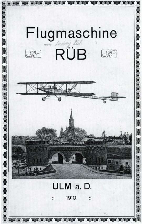
brochure (Figure 10) about his latest design: a biplane shown in Figure 11 that differed from
then-current designs by a number of details.(71) Interestingly, Rüb’s address inside this
brochure was given as Alramstraße 7/II in Munich, not in Ulm.
In the preface of the 1910 aircraft brochure,(71) Rüb declared the design as patented and, with
large self-confidence, sought to raise Germany to the same level in aeronautics as in other
German technology and industry. He stated that the shortcomings of extant aircraft were
overcome, and his design reflected recent advances and would therefore represent a new
standard type that would include all advantages of existing vehicles and eliminate all their
faults.
14Journal of Aeronautical History Paper 2021/01
Figure 9. Rüb’s company logo in Ulm, 1910 (4)
The biplane had a length of 24 m (more than
three times the length of the Bleriot machine,
for the time a truly “giant” aircraft!), a wing
span of 17 m (2.5 times), an elevator of 8 m
span, and two airscrews of 4 m diameter
each (2 times), see Figure . They were
mounted 2.3 m behind the wing’s trailing
edge and driven by a 50 HP engine.
The aft position of the airscrews was chosen
in order to have the wings in undisturbed air.
As in his prior design the wings were able to
feather and they could be rotated about the
span axis (in contrast to the Wright concept
of twisting). A simple fuselage frame would
allow for a quick assembly or de-assembly,
and the layout was given in the brochure in
form of technical drawings.
Finally, Rüb appealed to potential sponsors
with “German national, economical interest
and commercial vision.” Inside this
brochure, to support the visionary character,
Rüb had replaced the word “Schutzmarke”
by “Dem Ziel entgegen (towards the goal)”
in his company logo.(71)
Figure 10. Rüb’s aircraft promotion
brochure, 1910 (71)
15Journal of Aeronautical History Paper 2021/01
(a) Front view
(b) Top view
(c) Side view
Figure 11. Drawings of Rüb’s aircraft, 1910 (71)
Rüb estimated the weight of the aircraft without engine and crew as up to 360 kg and the
engine as 175 kg, based on a weight per horsepower ratio of 3.5 kg/HP. The fuel was
16Journal of Aeronautical History Paper 2021/01
estimated as 325 kg for 13 hours of operation and the crew of two persons at 75 kg each. The
total take-off weight therefore would be 1,000 kg (more than 3 times that of the Bleriot
machine), leading to a wing loading of about 13 kg/m² (almost a half) and a power loading of
20 kg/HP (almost 2 times).
Therefore, compared to the Bleriot aircraft, Rüb selected about half of the wing loading and
therefore thought it could fly with about half of the engine power/kg weight. The airscrew
blades were twisted and would rotate at 420 rpm, resulting in a tip speed of 66 m/s (71).
The aircraft’s performance was given with an airspeed of 17–20 m/s (60–70 km/h; 30–35 kts;
similar to Bleriot) and a maximum flight duration of 13 hours resulting in a range of 800–
900 km (500–560 miles). With 4 persons instead of 2 the airborne time would reduce to 7 hours
and the range accordingly (71). [Author’s comment: compared to aircraft performances of that
time these range and endurance data can only be judged as “adventurous” and maybe 10 years
ahead of time, but this reflects the spirit of the age: “nothing seems impossible.” Also, it was
very effective in advertising the project.]
For purposes of transport and stowage the vehicle could be disassembled by detaching the
wings and rotating them at the leading edge, such that they fold together. Elevator and rudder
were removed in one piece each. The fuselage could be folded to a remaining length of
11.5 m. With all parts placed close together, a volume of 11.5 m x 3 m x 3.5 m would result,
rolling on its three wheels of the undercarriage, and therefore able to be moved with ease. The
time of assembly or disassembly would be only half an hour (71).
The improvements over existing designs were elaborated in the following as: (71)
1. Flexible wings (Figure 12): Flexible ribs would make possible the use of maximum
allowable material stresses, resulting in less weight of the construction, and the wings
would adjust automatically to the wing loading [Author’s comment: this is equivalent
to passive airfoil camber morphing]. Such wings would give way to air gusts in order
to keep the flow attached, because pilots of rigid-wing aircraft reported flying in gusty
atmosphere was like riding a car without springs on uneven roads. [Author’s comment:
this can be interpreted as a first attempt at a gust alleviation system.]
2. Rotatable wings about the spanwise axis (Figure 13): Rüb intended to use this feature
for rolling the aircraft to the right or left, to compensate for air disturbances, and a
common pitch of both wings would lead to raise or lower the flight path. Take-off
would be simplified by simultaneous pitching of the wings and the horizontal tailplane.
A safer landing would be achieved by pitching the wings and the horizontal tailplane
up, because this would reduce the airspeed.
3. Foldable construction: The large frame could be folded, wings and tail surfaces
separated from it for ease of ground transport and stowing.
The flexible rib shown in Figure 12 was a specialty of Rüb, consisting of a tapered U-shaped
spring steel profile a and a support b, which were attached to the wing spar c. In spanwise
17Journal of Aeronautical History Paper 2021/01
direction the ribs were connected by a fabric cover. Depending on the amount of section lift a
rib would take on the shape d.
Figure 12. Flexible rib design (71).
Rüb considered the rotatable wings in conjunction with the rudder a more perfect control
system, since all moments could be counteracted, which at the time (1910) only the Wright
flyer provided. The long distances between wings and elevator and rudder were designed for
stability purposes, because they result in lower oscillation frequencies and thus are better fitted
to human reaction capabilities (71).
The rotatable wings, shown in Figure 13, contained roller bearings d, such that the wings could
be rotated about the spanwise axis and the trailing edge could take any position in the range
indicated by h. [Author’s comment: obviously this will cause large wing pitch control
moments, because the rotation axis is the leading edge, and the aerodynamic center is
approximately at the quarter chord.]
Figure 13. Rotatable wings about the spanwise axis (71)
In the following Rüb elaborated on different sizes of the propellers and the different tip speeds
with respect to the advantages and disadvantages, concluding with the comparison that “an
airscrew for an aircraft should not be small (like a ventilator with many rotor blades
transporting air through it), rather be large (a propeller with two blades only as a means of
transportation through the air). The physics by which Rüb tries to explain this are questionable:
18Journal of Aeronautical History Paper 2021/01
fast rotating propellers of small size, but many rotor blades cut the air in many thin slices that
are easy to convect, and consequently result in low propeller thrust. Large propellers with two
blades only cut thick slices of air, that generate more resistance against transportation, and thus
generate the thrust desired (71).
Therefore, the best condition for the rotor blades would be for the air to enter at rest, and to
leave it with as little velocity as possible, and this is why large propellers are best. [Author’s
comment: although not correct in its physics, the conclusion is correctly reflecting momentum
theory’s results.]
The brochure (at least the copy of reference (71)) concludes with Rüb’s call for foundation of a
society that should raise M 25,000 for building the first version of this aircraft, ending with the
hope to establish that company in Munich instead of his hometown Ulm that he considered too
small for this enterprise. Rüb attached a copy of a letter by Privy Counciller Carl von Linde,
Munich, dated May 26, 1910, offering M 5,000 in case Rüb successfully acquires the
remaining funds. Robert Bosch is reported to have done the same.
Rüb also attached a recommendation letter of Professor Finsterwalder dated 20 May 1910, an
article from the newspaper Ulmer Tageblatt dated 21 April 1910, and two further letters of
recommendation from Albert Hirth and Alfred Dierlamm, both of the Württemberg Society for
Ballooning. These recommendation letters were also sent to the city mayor of Ulm in April
1910, asking for further regard of his case with benevolence, but the city granted only M 500
from the funds for the poor, earmarked only for cost of living.
An expert opinion was also given by chief engineer Theodor Kober from Zeppelin dated
20 March 1910, who was a central point of contact for aircraft inventors seeking support and
expertise (72). He reported that he received several hundred of such requests in 1910 alone, and
only two of them he suggested worth of funding. One of them was Rüb’s aircraft, and Kober
gave many items of constructive criticism to Rüb, who introduced them into his design. The
Zeppelin foundation, albeit initially hesitative, finally offered M 12.000 (4). Kober’s prominent
position provided further credibility to Rüb and his design. Based on Kober’s expertise, the
Ulmer industrialist Carl Schwenk also granted M 600, but in general the funds came from
cities outside Ulm.
The famous August von Parseval, known for his airships, was also asked for an expert opinion
on Rüb’s aircraft design, and commented that everything “appears to be designed quite
rational,” but he had no further interest in it (73).
An article in Flugsport of April 1910 (74), also described Rüb’s aircraft in the same technical
detail as in his brochure, with the same drawings, including a perspective view shown in Figure 14.
19Journal of Aeronautical History Paper 2021/01
Figure 14. Perspective view of Rüb’s design (71).
With respect to the scarce funding from Ulm Rüb argued that some city councilor was
responsible for the unwillingness of the city to sponsor his project. Therefore, Rüb continuously
was at the edge of poverty, and tried all possible sources of getting the necessary funds. An
attempt to get money from a lottery also was blocked by the city. Nevertheless, he began work
on the construction after having found a workshop in the former “old stone factory” in
Schillerstraße 45, Ulm (4).
With the funds already obtained, Rüb (now 48 years old) began construction work. Employing
up to 9 workers in 1911, the fuselage framework, the elevator, and rudder took shape, wooden
propellers were manufactured, and the undercarriage prepared. He still promoted his project,
for example by means of postcards sold, that showed the impressive size of the fuselage and
the propellers, as seen in Figure 15 (a) and (b) (75), and (c) (76). Underlined in red is Ludwig
Rüb. The back of the postcard contained a short description of the machine.
The fuselage behind the cabin section is a triangular framework construction and reflects Rüb’s
experiences gained during his time at Zeppelin. That segment easily carried the weight of four
persons as shown in Figure 16 (76), with Rüb as second from the right. In reference (2) it is
stated that to the left of him his son Rolf would be sitting, but this is questionable, as explained
before. Probably the other son Emil was there.
After an aeronautics competition in October 1911 and inspired by the local enthusiasm about it,
Rüb invited members of the chamber of commerce (virtually all came), who were deeply
impressed, and of the city council (none of them were present) to get a look at the progress
with his aircraft. Rüb made any effort possible to get the required further funding.
20Journal of Aeronautical History Paper 2021/01
(a) Status of manufacturing, May 1911 (75)
(b) Status of manufacturing, August 1911 (75)
(c) Status of manufacturing, August 1911 (76)
Figure 15. Postcards of Rüb’s design, 1911
21Journal of Aeronautical History Paper 2021/01
Rüb’s euphoria would
erode in October 1911,
when Ernst Uhland (see
his previous role in
cancelling Rüb’s paddle-
wheel aircraft contract
1899-1902) requested a
proof of usage of the
Zeppelin funding, and
demanded a refund of
M 2,000, based on
rumors about Rüb’s
progress, and alleged
alcoholic problems. In
an accompanying letter it
was pointed out that
obviously Rüb did not
work on the envisioned Figure 16. Static loading test of fuselage aft portion, 1911 (76)
simple proof of concept
for which the funding was granted, rather on a more advanced design that would require
additional funds (77). This stopped all the work on 28 October.
Rüb desperately approached the city council of Ulm again for support. With a further expert
opinion from Alexander Baumann (in 1911 the first professor for airships, aeronautics and
motorized roadable vehicles in Germany, established at the Technical University Stuttgart), as
support of Rüb’s request, on 15 December 1911 he finally got at least some support from the
city to set up a wooden stable (78), provided he would construct it on his own. Some progress
was still made in 1912, when Rüb got a 50 HP engine from a Daimler on loan for half a year.
Despite this, Rüb again ran out of money, and once again asked the city for continued support
by M 5,000 (79), again threatening that in case of denial he would finally leave the city. The
answer of the council could be easily predicted: they denied any further support.
Ludwig now tried his fortune in his typical way: he gave up his project, stating that by then it
was outdated already. He then proposed a new aircraft with a steel frame that also should be
able to take-off and land on water and was not shy in asking again for money. The city council
must have been much bewildered and rebuffed, and consequently denied all support (80). This
finally left Rüb alone with his problems and his debts of the order of several thousand Marks.
As person without employment and bankrupt he was again left to the mercy of the funds for the
poor. A final grant of M 500 of the city of Ulm in December 1912 was intended to get rid of
him entirely. Rüb then considered immigration to the US or to Argentina (likely to the great
relief of the city council), but he moved back to Munich in 1912, and in 1914 to Stuttgart.
22Journal of Aeronautical History Paper 2021/01
In summary, Rüb had spent about M 20,000 in Ulm, it is surprising how many cities he visited
for fund-raising, how many renowned persons of public life he knew, and that despite his
unsuccessful developments he still was able to acquire money for his projects. Zeppelin,
Linde, Bosch as industrial personalities, Finsterwalder, Hirth, and others from the scientific
community – all of them still considered him as person with high skills, capabilities and vision
– perhaps it was the latter that was the most significant trait he shared with them.
6. SECOND RÜB HELICOPTER 1913-1918
Rüb moved to Stuttgart and in 1913 started the design of a new helicopter similar to his 1902
effort. He found a new sponsor in Dr. Friedrich Wilhelm Albert Hauff, an industrialist and
prominent person with a chemical factory backing up his wealth, which was partly used to
sponsor many technical projects, amongst them Rüb’s helicopter. With the support of Hauff
(the actual date is unknown), Rüb advanced the design and approached the military with the
claim that a helicopter would be much better suited as an observation platform than the usual
balloons, which required several trucks and many ground staff, as well as huge amounts of
hydrogen. Without the need of all that equipment, the helicopter could go by itself where it
was needed and would even take an active combat role if equipped with a machine gun. The
air force inspectors in Berlin expressed some interest in Rüb’s helicopter and withdrew his son
Rolf from the front lines to assist his father in May 1917. (In August 1914 Rolf was for
military service, (1) and from then on Ludwig continued the design together with his son Emil.
No records exist whether Emil was called for duty or not; if so, he must have been released
from it in 1916, because he is also mentioned as inventor on the 1917 patent application.
Ludwig was now age 50 and too old to be called for duty.)
Ludwig founded Rueb’s Flugtechnische Versuchs-Anstalt (Rüb’s Aeronautical Test Facility),
located at Alexanderstraße 36 in Stuttgart, where between 1915 and 1918 the new helicopter
was built.(81) Ludwig and Emil applied for a patent for their “Rotoplan” on 19 February 1917,
asking for secrecy because it was considered of interest for the army, and for accelerated
processing for the same reason.(82) The following description is a condensed form of that
patent application.(82)
The Rotoplan could take off vertically and land in glide condition, even without engine
power, which would be a superiority over existing attempts. In contrast to other designs,
it had a total lifting surface loading per kg weight as low as fixed-wing aircraft with tip
speed and pitch angle also comparable to fixed-wing conditions in flight. This low wing
loading [Author’s comment: better: disk loading] is needed for minimum vertical
autorotation speed and requires a large rotor radius.
Highlighted as “new” were: first, the capability of gliding [Author’s comment: autorotation] as
a principal design feature; and second, the technical solution to do so.
The technical drawings in Figures 17 to 23 were attached to the patent application to explain
the design details; the symbols and their meaning are listed in Table 1.
23Journal of Aeronautical History Paper 2021/01
Table 1. List of symbols used in Figures 17 to 23
Symbol Explanation Symbol Explanation
a Inner shaft m Pitch bearing eye of the rotor blade
b Upper rotor n Rotor shaft
c Outer shaft o Static outrigger of the hub
d Lower rotor p Pitch bearing eye of the hub
e Nose beam of the rotor blade q Pitch horn
f Upper main beam of the rotor blade r Pitch link push rod
g Lower main beam of the rotor blade s-v Swashplates
h Flexible ribs w Control lever
i Spars x Worm gears
k Diagonal struts between e and f y Worm drive
l Diagonal struts between g and e, g and f
The general arrangement shown in Figure 17 depicts a coaxial rotor design with an inner shaft
a driving the upper rotor with blades b and an outer hollow shaft c driving the lower rotor with
blades d. The counter-rotation of both rotors eliminates the individual torque of each of them.
Each rotor consists of four blades, but three blades can also be used.
Side view
Wing control for Rüb’s Rotoplan
Gearbox
Figure 17. General arrangement, 1917 (82)
24Journal of Aeronautical History Paper 2021/01
A sketch of the blade attachment to the rotor hub as built by the Rübs (three blades instead of
four as sketched in the patent) is shown in Figure 18. It is remarkable that the main blade spar
is not oriented radially outward from the hub center but offset at the root where it is connected
to the hub at two widely separated points at the blade root. This sketch may help in understanding
Side view
the description of the patent application.
Top view, 1 blade only
Side view
Front
t
Figure 18. Sketch of Rüb’s blade attachment to the hub
o Zoom of hub
30
o
60
D
Pitch link
Side view
Spar
C
Front view A Pitch B
horn
Shaft Hub, side view
C Spar
Top view
Hub
Figure 19. Rotor blades (82)
The rotor blade’s design must fulfill three requirements:
1. To be strong enough to carry the bending moments resulting from the center of air
loads, which, due to the linear increasing speed towards the tip, will be located in the
outer portion.
2. Strong enough to carry the torsion moment, which increases towards the hub.
3. Allow for rotor blade pitch variation.
25Journal of Aeronautical History Paper 2021/01
These requirements were fulfilled by designing the blade spar as a triangular framework shown
in Figure 19. Beams or tubes in spanwise direction form the edges of the triangle, with e and f
at the top and g at the bottom. The upper ones are connected by struts i, rigidly attached to the
flexible ribs h, which provide the airfoil camber. These flexible ribs – although presented by
Rüb as early as 1902 during his presentation of the first helicopter design in Munich and later
on his fixed wing aircraft build in Ulm 1910, see Figure 11, were now patented by him and his
son Emil (82) (see Figure 20).
All beams or tubes were connected to the others by zig-zag struts, ensuring bending and
twisting stiffness. No pre-twist is foreseen in the design, because the required twist is thought
to automatically develop during rotation by the aerodynamic loading of the blades, caused by
the flexible ribs h.
Figure 20. Patented rotor blade rib (82)
Due to the increasing lift towards the blade tip the ribs will accordingly bend up and thus
introduce the required twist for best performance. This concept was emphasized as absolutely
new. [Author’s comment: it was new for application in a helicopter, but Rüb made use of this
concept before on his airplane wing design. Nevertheless, this represents rotor blade morphing
– 100 years ago.]
In order to carry the expected high flap bending moment at the blade root, a large distance of
connecting points at the hub was required, as shown in the lower left of Figure 19. The
connection carrying the highest bending moment has the largest cross-section and thus the
largest framework stiffness. The bending moment decreases linearly towards the outer
connection point, and therefore the framework is tapered between the points m – m. Rüb
emphasized this hub connection as innovative. [Author’s comment: essentially a stiff mount
was considered instead of the flapping hinges used by de la Cierva a few years later. The long
distance between mounts m – m reduces the vertical forces acting there.]
The hub for a four-bladed rotor is shown in Figure 21; a three-bladed rotor would have three
equidistantly spaced arms instead. Around the hub arms o are arranged (top graph) which are
conically shaped (lower graph) to carry the large loads expected. Blade connection points are
26You can also read