Additive Manufacturing for Property Optimization for Automotive Applications
←
→
Page content transcription
If your browser does not render page correctly, please read the page content below
Additive Manufacturing for Property
  Optimization for Automotive Applications
  Pum Kim (PI), Vidya Kishore,
  Srdjan Simunovic, Vlastimil Kunc - ORNL
  Ellen Lee – FORD
  Xiaoyu Rayne Zheng - UCLA

   June 23rd, 2021                                                                                          Project ID#: mat200
ORNL is managed by UT-Battelle, LLC
for the US Department of Energy

                           This presentation does not contain any proprietary, confidential, or otherwise restricted information.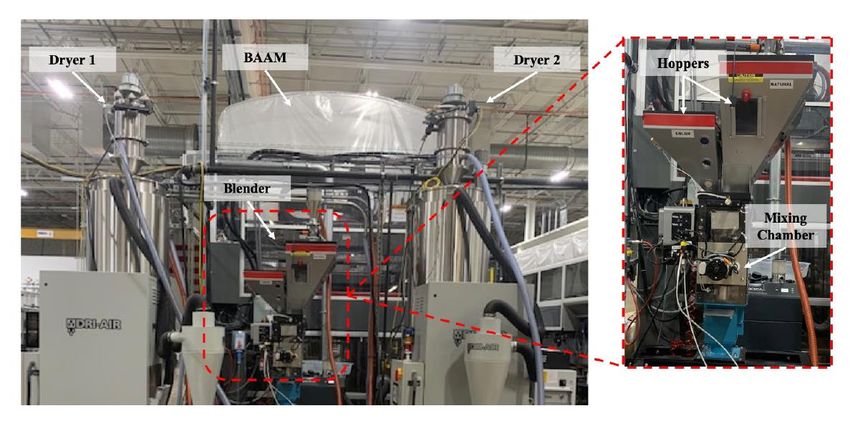
Overview

                Timeline                                  Budget                                             Partners

    ➢ Project start date: Oct 2020       ➢ DOE project funding: $500K/yr              ➢ Ford Motor Company - Industry partner
    ➢ Project end date: Sept 2023           • DOE: 100%                                 Ford project lead: Ellen Lee
    ➢ Percent complete: 15%              ➢ Funding for FY21: $500K                    ➢ UCLA - Subcontract
                                                                                        UCLA project lead: Xiaoyu (Rayne) Zheng

                                                          Barriers and Targets
     ➢ Barrier: (1) Lack of understanding of properties with respect to fracture and energy absorption*, (2) Lack of
       predictive engineering and modeling tools*, (3) Cost/availability of most lightweight materials and current
       manufacturing processes are not competitive*                                (* Ref.: Light-Duty Workshop Final Report (DOE-VTO) )

     ➢ Target: (1) Design, optimization, and performance simulation of tailored 2.5D cellular structures for extrusion-
       based AM incorporating ML, and (2) Fabrication and performance evaluation of parts printed using the multi-
       material BAAM system and OPP technology.
2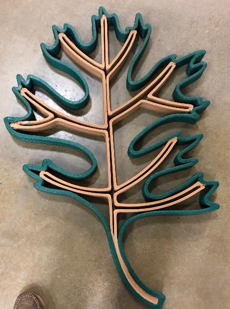
Relevance
                   Overall Objectives                                         VTO’s Mission
  ➢ Combine multiple technologies associated with          ➢ Reduce the transportation energy cost while meeting
    AM to increase the performance and reduce the
                                                             or exceeding vehicle performance expectations.
    manufacturing cost and the weight of components
    using composites.
                                                                            Our Strategies
                   Current Limitations
                                                           ➢ Large-scale structure optimized for structural design
  ➢ Design constraints with conventional
                                                             and multi-material placement printed in BAAM.
    manufacturing methods → AM
                                                           ➢ Control technique of an out-of-plane printing will be
  ➢ Design requires a series of stress simulation -
                                                             developed, and the sub-component of a vehicle will be
    design modification cycles → ML
                                                             fabricated.
  ➢ AM provides design flexibilities in 2D but still has
                                                           ➢ ML algorithm development for a sub-component
    constraints in 3D
                                                             structure with tailored energy absorption
    → Out-of-plane printing
                                                             characteristics
  ➢ AM for large scale utilizes single material
    deposition for large scale printing
3
    → multi material printing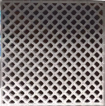
Milestones
                                                                                                                         Y1          Y2          Y3
                                                                                                                    Q1 Q2 Q3 Q4 Q1 Q2 Q3 Q4 Q1 Q2 Q3 Q4
         T1.M1   Part design selection based on discussions with the industry partner (e.g., frontal bumper)
         T1.M2   Load cases and criteria for mechanical responses (e.g., deflection and energy obsorption)
         T1.M3   Mechanical property evaluation for BAAM materials.
         T1.M4   Material composition optimization for BAAM printed structures.
Task 1
         T1.M5   Scalability test of the of the structure from small-scale prints to BAAM
         T1.M6   Toolpath optimization for the latticed structures for BAAM with multi-material
         T1.M7   Demonstrate printing of performance optimized multi-material structures on the BAAM system
         T1.M8   Mechanical testing and evaluation of a BAAM printed structure

         T2.M1   Part design selection for out-of-plane printing with the industry partner (e.g., door arm rest)
         T2.M2   Define load cases and criteria for mechanical responses (e.g., deflection and energy obsorption)
         T2.M3   Performance simulation for the out-of-plane structure
         T2.M4   Material property evaluation for a multi-axis extrusion system
Task 2
         T2.M5   Slicing technology development for the multi-axis extrusion system
         T2.M6   Toolpath planning for the out-of-plane structure
         T2.M7   Robot arm control & extrusion control optimization for the multi-axis system
         T2.M8   Demonstrate printing of an out-of-plane property optimized structure

        T3.M1    Development of a simulation technique for 3D-printed lattice structures
        T3.M2    Calibration of the simulation parameters (small-scale)
        T3.M3    Perform simulations for multiple lattice structuers and material combinations (small-scale)
        T3.M4    Mechanical tests for multiple lattice structures and material combinations (small-scale)
Task 3
        T3.M5    Development of an ML Approach & Training Data Acquisition for lattice structures
        T3.M6    Generation of Tailored Lattice Structures and Evaluation (small-scale)
        T3.M7    Lattice structure combined with self-sensing material (small-scale)
4      T3.M1-6   Regular milestones for BAAM and stretched milestones for out-of-plane printing structure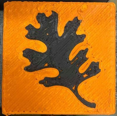
Approach
      MATERIAL & DESIGN OPTIMIZATION                                     SIMULATION                         ARTIFICIAL
          Tailored Lattices & Multi-Materials                                                             INTELLIGENCE

                                                                    Deformation Prediction
    Lattice Structures with Tailored Stress-Strain Response       Strength/Stiffness Prediction

    Fiber-Reinforced Thermoplastics, Elastomers,
       Thermoplastic Foams, Polymer Blends

                                                                        TESTING                      PERFORMANCE
          FABRICATION (Extrusion AM)                                                              Multi-Property Optimized
                                                                                Mechanical
                                     Out-of- Plane AM                         Properties such            Structures
                                Single Material (Mid-Scale)                     as Energy
                                                                               Absorption,
                                                                                 Stiffness,
                                                                                 Strength

5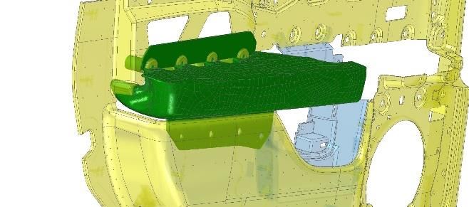
Technologies
    • Multi-material extrusion BAAM system
    • Lattice optimization algorithm

    • Simulation technique for lattice deformation

    • Out-of-plane printing with a robot arm (5 axis)

    • Design selection algorithm via machine learning (UCLA)

    Target Applications
    • Front bumper and door panel arm rest

6               Frontal bumper design from FORD (blurred)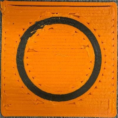
Task 1
                                     Task 1: Design Requirements for a Bumper
    Frontal Bumper (Energy Absorber Portion) of Passenger Vehicle
    Conflicting design/performance requirements:

    • Pendulum intrusion testing:
         – Large footprint impactor at low speed (2.3 mph) with relatively large deformation (< 85 mm)

    • Leg flexion testing:
         – Small footprint impactor at high speed (24.6 mph) with relatively small deformation (< 13 - 22 mm)
           replicating the scenario of impact with a pedestrian’s leg

                                                                                            [Ref]

                                                  Pendulum test                                                                           Leg test
7                 [Ref] Katkar, A.D. and Bagi, J.S., Bumper Design Enhancement through Crash Analysis. Int. J. Eng., Tech., Mgmt. & Appl. Sci. 2015.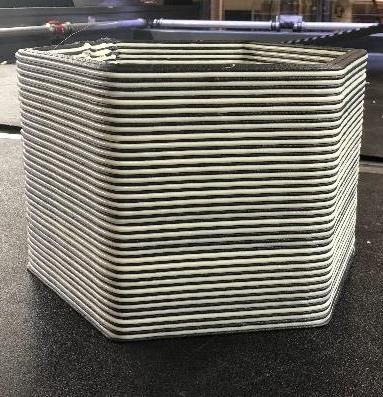
Task 1
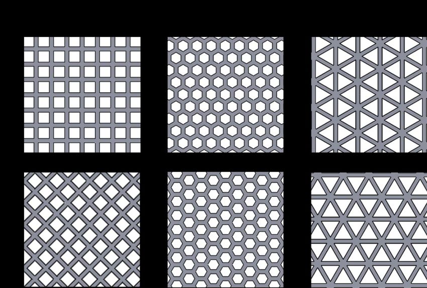
Multi-Material Large-Scale Printing of Optimized Structures
Multi-Material Printing on the Big Area Additive Manufacturing System
Alternating materials
Complex structures between layers
Local reinforcement
• Enables printing of with multiple materials in a single build for site specific
properties or functionally graded material (FGM) structures.
• Blending system enables mixing feed pellets with foaming agents for
extruding thermoplastic foams (density ≥ 0.2 g/cc) for lightweight
8 * Printed in previous years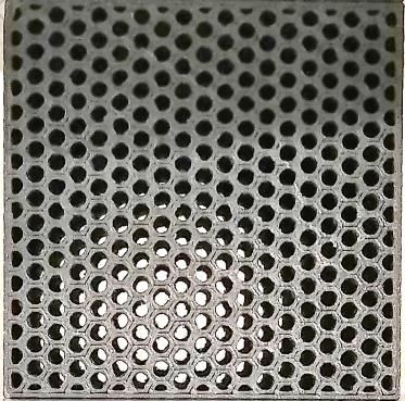
Task 1
                                           Materials Selection
                                          For multi-materials printing
         BAAM-Printable Materials
                                          • Similar processing temperature range.
    • Low Temperature Thermoplastics &
      Composites                          • Chemical and rheological compatibility for good interlayer bonding, and
                                            continuous printing for graded properties.
    • High Performance Thermoplastics &
      Composites                          For thermoplastic foam printing

    • Bio-Derived Materials               • Feed material processable below the degradation temperature of foaming
                                            agents.
    • Magnetic Materials
                                          • Layer time to be optimized to prevent warping/cracking.
    • Elastomers
                                          Materials selection criteria for preliminary screening
    • Foams
                                          • Low temperature thermoplastics/composites compatible with expandable
    • Dissolvable Polymers
                                            microspheres (foaming agents).
    • Recycled Materials
                                          • Elastomeric matrices with good energy absorption properties.
                                          • Materials processable as blends (stiff and elastomeric material blends) to
                                            tailor mechanical properties.

9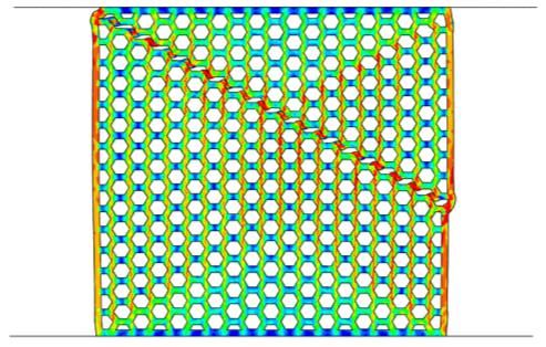
Task 1
                     Material Properties Characterization for Optimization

                                                           CF/ABS                             CF/ABS Foam

           Gravimetric blender for mixing              Examples of test parts printed on the BAAM for individual material properties
          feed pellets and foaming agents.                                            characterization.

                                                    Materials chosen for preliminary screening: CF/ABS Foam, TPU
                                                    (Elastomer), TPU Foam, ABS, ABS Foam, CF/ABS & TPU blend, CF/ABS
                                                    & TPU blend foam, Xenoy® 1102.
                                                    Properties of interest for optimization: Dynamic mechanical properties
                                                    (torsion, flexure), tensile properties, flexural properties.
       Feed Pellets       Expandable Microspheres   Other properties of interest for application: Impact, density
     (Ex: 20 CF/ABS)          (Foaming Agent)
10
Task 1
Reference Design
(Bumper with supporting inner curved structure)
• 3 parts: Base, long & thin inner structure, short & thick inner structure
• Challenges
– Base has a curvature. → Out-of-plane printing in BAAM
• Technology to be developed (slicing and control).
– Small features
• Not feasible in BAAM → Thicker design with a softer material (TPU foam)
– Continuously varying thickness
• Extrusion flow rate control very thin
– Switching materials (short structure vs. long structure)
thin
• Layer time calibration based on the heat capacity
thick
Bumper design from FORD (blurred)
Conceptual image: Not an actual
11
design for this projectTask 1
Slicer Modifications
- Slicer 2.0 under development will incorporate the capabilities for slicing curved parts
- Currently the bumper toolpath was created using the slicer of Mazak hybrid manufacturing system*
* Slicing performed by Tom Feldhausen and Rebecca Kurfess, ORNL
Bumper design from FORD (blurred) θ
Top view Angled view
12
Conceptual animation: Not an actual design for this projectTask 1
Subtasks in Progress in This FY
• Printing test samples with the selected materials for mechanical properties characterization.
• Machining printed parts for harvesting test samples. Material
Characterization
• Testing of mechanical properties.
• Print trials with the reference design for printability test with CF/ABS and TPU to identify potential
design related challenges that may arise for large-scale printing moving forward.
13 Any proposed future work is subject to change based on funding levels.Task 2: Arm Rest
Topology Objective* = Minimize Strain Energy,
Load case and design criteria
Constrain Mass Fraction to 25%
*Performed by Brian Knouff at ORNL using Genesis Topology Tool
F = 670 N
Requirement: < 15mm deflection
FEM Simulation
Stress [kPa]
Mass Fraction of 25%
*Designed by Amiee Jackson at ORNL
14Task 2
Subtasks in Progress in This FY
• Further optimization of design of armrest.
• Print trials in an out-of-plane printer with 5-axis robot arm.
– It is a new system, and the control framework should be further calibrated.
• Printing test samples for mechanical properties characterization.
Material
Characterization
• Testing of mechanical properties.
• Deformation prediction of the optimized design via FEM simulation
15 Any proposed future work is subject to change based on funding levels.Task 3
Task 3: Simulation Technique Developed
➢ Simulation via Finite Element Method (FEM)
➢ Constitutive Relations Used:
• Elasticity
• Plasticity
• Damage/Element removal
• Contact detection/repulsion Crush simulation
Import
Import
Material
Initial Imperfections
Orientations
Property direction assignment Crush simulation
Frequency Analysis
16Task 3
Lattice Structure Designs
Lattice structure designs
Experimental samples
(experiments performed in FY2018)
17
Boundary/load conditionsTask 3
Fracture/Crush Pattern from Simulation
(a) (b)
(a) (b)
σeq (MPa)
(c) (d) σeq (MPa)
(c) (d)
(e) (f) (e) (f)
18Task 3
Comparison: Simulation vs. Experiment
(a) (b)
σeq (MPa)
(c) (d)
(e) (f)
19 Experiment performed in Yr 2018Task 3
Comparison: Simulation vs. Experiment (Stress-Strain)
Experiment Simulation
12 12 12
Stress (MPa)
9 9 9
6 6 6
3 3 3
0 0 0
0% 5% 10% 15% 20% 25% 30% 0% 5% 10% 15% 20% 25% 30% 0% 5% 10% 15% 20% 25% 30%
12 12 12
Stress (MPa)
9 9 9
6 6 6
3 3 3
0 0 0
0% 5% 10% 15% 20% 25% 30% 0% 5% 10% 15% 20% 25% 30% 0% 5% 10% 15% 20% 25% 30%
Strain Strain Strain
20 * Manuscript submitted to Materials & Design Journal, currently under review.Task 3
Plans for Task 3
• Further crush simulations on various lattice designs
– Training data for ML
Various
• Material property library for simulation lattice
designs
• Development of machine learning framework for lattice
structure design optimization
21 Any proposed future work is subject to change based on funding levels.Collaborations
• Industry Partner: Ford Motor Company
– Ellen Lee, Iskander Farooq, Zach Pecchia, Sushmit Chowdhury,
Matthew Rebandt
• Subcontractor: University of California, Los Angeles (UCLA)
– Prof. Xiaoyu Rayne Zheng,
22Remaining Challenges
➢ Task 1
• Slicing and creating a toolpath of a single bead structure on a curved surface for
the entire part printing.
• Printing calibration for a small feature with a small nozzle.
➢ Task 2
• Robot arm control
• Toolpath generation without collision on a curved structure for out-of-plane
printing
➢ Task 3
• Machine learning algorithm development for a bumper design
23Proposed Future Research
➢ Task 1
• Printing test samples with the selected materials for mechanical properties characterization.
• Machining printed parts for harvesting test samples.
• Testing of mechanical properties.
• Print trials with the reference design for printability test with CF/ABS and TPU to identify potential
design related challenges that may arise for large-scale printing moving forward.
➢ Task 2
• Further optimization of design of armrest.
• Print trials in an out-of-plane printer with 5-axis robot arm.
• Printing test samples for mechanical properties characterization.
• Testing of mechanical properties.
• Deformation prediction of the optimized design via FEM simulation
➢ Task 3
• Further crush simulations on various lattice designs: Training data for ML
• Material property library for simulation
• Development of machine learning framework for lattice structure design optimization
24 Any proposed future work is subject to change based on funding levels.Summary
➢ Target:
(1) Design, optimization, and performance simulation of tailored 2.5D cellular structures for extrusion-
based AM incorporating ML, and
(2) Fabrication and performance evaluation of parts printed using the multi-material BAAM system and
OPP technology.
➢ Progress:
(1) BAAM materials have been prescreened.
(2) Single bead features have been sliced using a metal welding-based AM hybrid system.
(3) Armrest has been designed based on topology optimization.
(4) Simulation framework developed for a lattice crush response with various lattice types.
(5) Simulations have been verified by experimental results.
25You can also read