Assessment of Design Impacts on Space Shuttle Operations and Recommendations for Manned Space Vehicle Programs
←
→
Page content transcription
If your browser does not render page correctly, please read the page content below
Assessment of Design Impacts on Space Shuttle Operations
and Recommendations for Manned Space Vehicle Programs
                                      Thomas Coffee
                                      Department of Aeronautics & Astronautics
                                      Massachusetts Institute of Technology

             January Operational Internship Experience
                   NASA Kennedy Space Center
               Space Shuttle Operations Directorate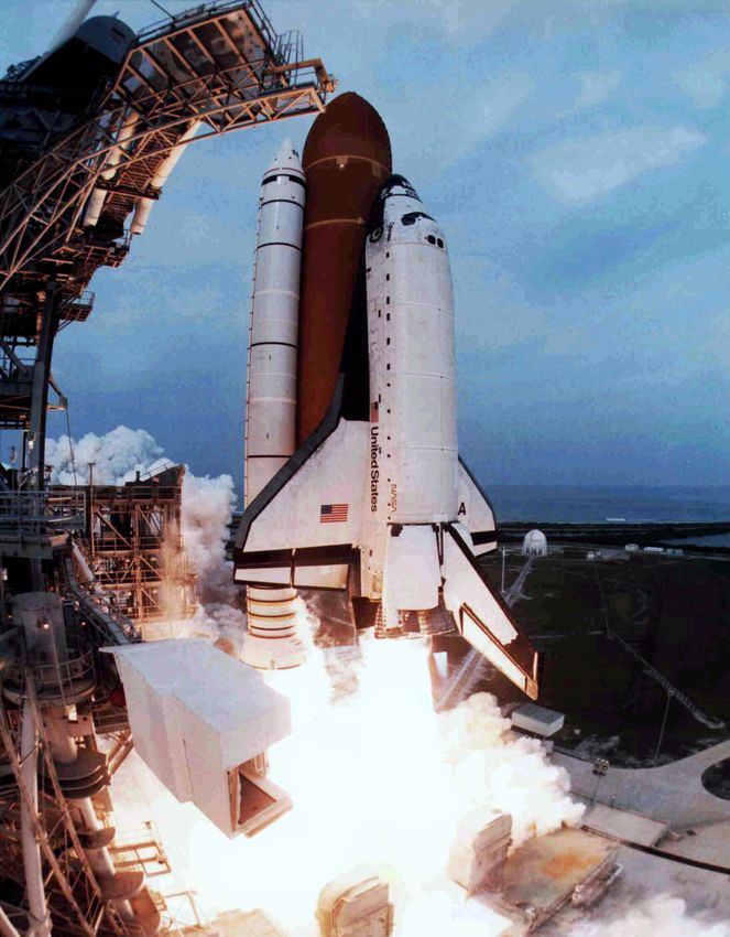
Acronyms
AC ...............Alternating Current
AFB .............Air Force Base
BSTRA ........Ball Strut Retention Assembly
CAIB ...........Columbia Accident Investigation Board
CG ...............Center of Gravity
CPU .............Central Processing Unit
DC ...............Direct Current
DFRC ..........Dryden Flight Research Center
ET ................External Tank
FRCS ...........Forward Reaction Control System
GPS..............Global Positioning System
GSE .............Ground Support Equipment
HDTV..........High Density Television
HQ ...............(NASA) Headquarters
HVAC..........High Volume Air Conditioning
ISS ...............International Space Station
IVHM ..........In-Vehicle Health Monitoring
JAXA...........Japan Aerospace Exploration Agency
JOIE.............January Operational Internship Experience
JSC ..............Johnson Space Center
KSC .............Kennedy Space Center
LH2 ..............Liquid Hydrogen
LOX.............Liquid Oxygen
LRU.............Line Replaceable Unit
MLP.............Mobile Launch Platform
MSFC ..........Marshall Spaceflight Center
MSGC..........Massachusetts Space Grant Consortium
MTBF ..........Mean Time Between Failures
NASA ..........National Aeronautics & Space Administration
NSLD ..........NASA Shuttle Logistics Depot
OMM ...........Orbiter Major Modification
OMS ............Orbital Maneuvering System
OPF..............Orbiter Processing Facility
PCR .............Payload Changeout Room
QA ...............Quality Assurance
RFID............Radio Frequency Identification
RSB .............Rudder/Speed Brake
SRB .............Solid Rocket Booster
SRU .............Shop Replaceable Unit
SSC..............Stennis Space Center
SSME ..........Space Shuttle Main Engine
SSTO ...........Single Stage to Orbit
TACANS .....Tactical Air Navigation System
TPS ..............Thermal Protection System
USA.............United Space Alliance
USAF...........United States Air Force
VAB ............Vehicle Assembly Building
VDC ............Volts Direct Current

Cover Image: Space Shuttle Columbia at liftoff [Credit: NASA].
Introduction
As conceived in the early 1970s, the Space Shuttle would launch forty times per year, lowering launch
costs by an order of magnitude versus expendable launchers to ~$1000/kg to Low Earth Orbit. The promise
of a centralized, reusable launch architecture providing the nation cheap access to space captured a winning
bulk of political and public sentiment until Challenger exploded on liftoff in 1986. In the ensuing review of
the program, it became evident that both these estimates outbid reality by roughly ten times: the Shuttle has
since launched roughly four times per year, with full-accounting launch costs somewhat higher than the
expendable launchers it was meant to replace. At the same time, previous idealism about future reusable
launch vehicles has been severely shaken.

During January 2005, I visited NASA’s Kennedy Space Center to examine the operational issues leading to
the Shuttle’s failure as a low-cost launch system and develop recommendations for future reusable vehicle
programs. Over three weeks, I had the opportunity to observe Shuttle operations preceding the Return to
Flight after the Columbia accident, and to interview several engineers and managers from each division of
the NASA Shuttle Processing Directorate and the United Space Alliance. This report outlines the major
themes generated from this experience and suggests possible directions for future human spaceflight
systems.

Overview
To students of the space program, it seems surprising that the Shuttle’s capabilities were so misjudged. At
its inception, the program foreran the world’s most renowned technical organization, the recent champion
of the most spectacular engineering achievements in human history. Yet precisely this euphoric
environment contributed to the Shuttle’s misalignment with its stated objectives.

Performance Optimization Versus Reusability
Veterans of the Apollo program were accustomed to performance-driven, expendable systems only loosely
constrained by budgetary considerations. As a cost-driven, reusable system, the Shuttle required a different
engineering approach, which it did not fully receive. While the vehicle was built to comply with reusability
requirements, it was optimized primarily for flight performance (Figure 1). The high performance
sensitivity of rocket propulsion systems provided some justification for this, but lifetime operational impact
ultimately dwarfed the gains accomplished by this methodology.
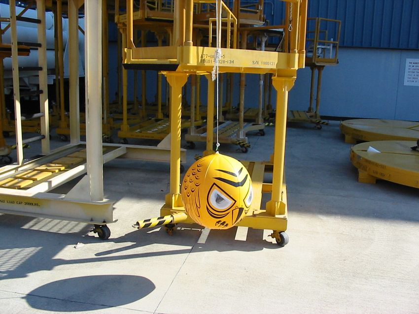
Figure 1: The Space Shuttle design optimized flight performance over operations [Credit: NASA].

The Snowball Effect
Can a misplaced balance between performance and operational costs really explain an order-of-magnitude
gap between predictions and reality? A simplistic model provides some insight into how this may occur:
suppose that every unit of some resource involved in the program in turn requires k units of resources in
overhead supporting the associated operations, where k < 1. If we assume the same marginal overhead
factor for these additional resources, we require another k2 units of resources in support, and so on. Hence,
the total overhead factor is   1 + k + k 2 + L = 1−1k . The total resources required in this model show
remarkable sensitivity to k, as shown in Figure 2.
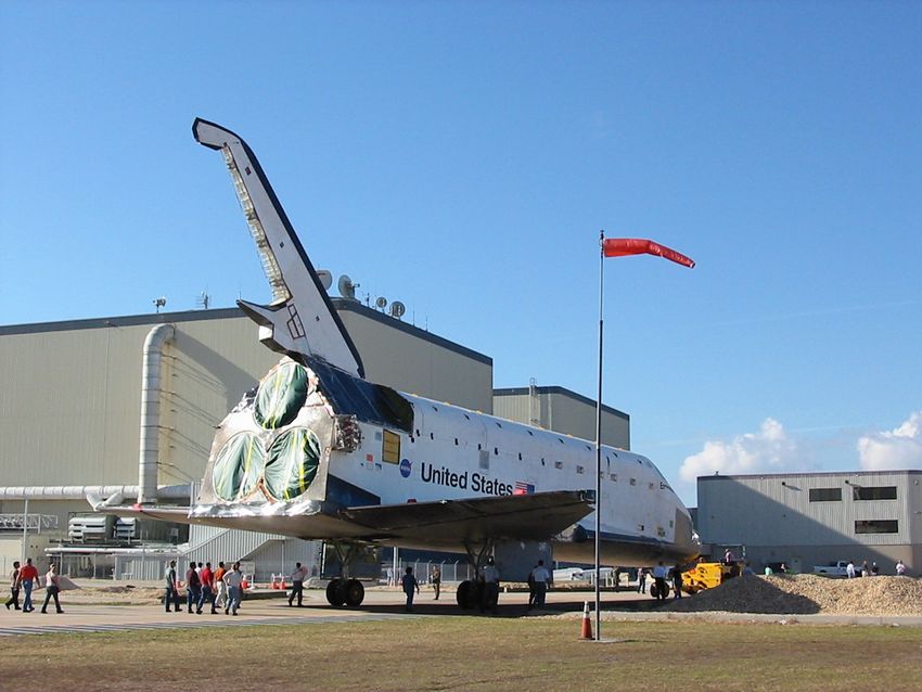
Figure 2: A simple model of overhead propagation illustrates the Snowball Effect.

In reality, of course, the factor k varies at every level of support and for every type of resource. However,
small miscalculations in predicting operational overhead can plausibly account for large multiplicative
deviations in total cost. This Snowball Effect applies to a number of different resources:

         •     Infrastructure. More equipment requires more supporting infrastructure, which itself
               requires more supporting infrastructure.
         •     Personnel. More people require more facilities and people to support and coordinate them,
               which require still more people.
         •     Processing Time. The longer a process takes, the more tasks are required to maintain health
               and organization, adding more time to the process.
         •     Testing Completeness. The more tests performed, the more parts must be moved to perform
               the tests, hence the more parts must be tested.
         •     Requirements. More requirements generate more interactions with other requirements, which
               generate still more requirements.

From the intuition above, small reductions in the marginal overhead factor associated with each of these
resources can produce dramatic savings in total cost.

Three Targets for Operational Costs
As with any partially reusable system, the operational costs of the Space Shuttle program can be
decomposed into a product of three factors: the repairs required, the tasks required to perform these repairs,
and the resources required to perform these tasks (Figure 3). Each of the recommendations presented below
addresses one or more of these elements.

                  Figure 3: A product of three factors determines total operational costs.
Design Recommendations
Most of the design recommendations discussed herein were suggested by multiple individuals involved in
Shuttle operations; a select few are based purely on personal observations. Quotations come from senior
engineers at NASA or United Space Alliance except where noted. Names of individuals have been
withheld to protect privacy. Many examples discussed illustrate multiple problems; however, most are
discussed only in the context of one most relevant issue.

Trade Performance for Robustness
Cost-effective reusable systems must maintain higher margins on components than one would choose for
expendable systems. The Space Shuttle was built with low margins and a few particularly striking
vulnerabilities. Disasters associated with these vulnerabilities are generally avoided by meticulous
processing and inspection, which drives up processing time and costs. By contrast, some NASA engineers
offered Russian programs as examples of more robust systems with higher margins, which achieved
substantially lower absolute costs in both development and operations. We focus here on a few cases where
small performance hits could make a large difference in servicing requirements:

Flight Deck Windows. The windows of the cockpit encounter micrometeoroids and orbital debris at high
relative velocities, creating dents and cracks during flight. The combined constraints of aerodynamic
heating and material resilience require polishing the windows to a tolerance of 0.0006 inches. Technicians
inspect the 33 surfaces of all ten panes with a hand-held microscope, requiring a dedicated week to inspect
a single surface. In addition, 1-2 panes per flight must be replaced entirely. Relatively low-impact changes
in total window area or materials could substantially reduce the time required for processing. (Figure 4)

 Figure 4: Orbiter windows require enormous attention and protection during Shuttle processing.
 Left: protective covers shield the windows inside the OPF. Right: cockpit rear windows incur less
damage by virtue of the flight path and payload bay doors, but require equally extensive inspection.

Cold Plates. Many electronic components are cooled via surface-mounted water or freon honeycomb cold
plates, with face sheets not much thicker than aluminum foil. Technicians replace these components, after
servicing, in an awkward position requiring significant force while in contact with the plate. Plates are
often damaged, though verifying damage requires taking molds of potential defects and applying optical
magnification. Replacing the cold plates requires exchanging shipments with facilities in Palmdale,
California. Here, a reasonably lightweight dent-resistant coating could suffice to mitigate the problem.
(Figure 5)
Figure 5: Avionics boxes are mounted on cold plates buried in racks like these. Left: the front
middeck racks contain most Shuttle avionics, where space limitations limit access and safe numbers
of personnel. Right: technicians must operate dexterously yet forcefully inside deep, narrow cavities.

Propulsion Concept. The engineers at USA have suggested that no propulsion system based on a high-
order chemical reaction will become “operational” before revolutionary advances in propulsion technology
are realized, due to the stresses and hazards involved. The Shuttle’s propulsion system was optimized for
chemical specific impulse, creating many issues associated with the extreme demands of cryogenic fuels,
particularly liquid hydrogen (some discussed later).

Main Engines. The Space Shuttle Main Engines (SSMEs) were designed to be operated for several dozen
flights without servicing, but are currently disassembled for testing and reassembled every flight. A change
of contractor has been recently effected in order to address the engines’ robustness.

  Figure 6: Space Shuttle Main Engines are disassembled for testing and reassembled every flight.
  Left: the stunning entanglement of fluid and electrical lines makes inspection and testing a multi-
  month process. Right: removing and replacing engines requires custom-built heavy machinery to
           provide the necessary combination of force, precision, and compatible geometry.

Hydraulic Power Lines. Many Orbiter functions draw mechanical power from hydraulic fluid lines
carrying hazardous compounds that invariably spring leaks. Some have proposed replacing these hydraulic
systems with substantially more massive batteries, which also contain hazardous materials but may prove
far more benign for servicing.

Thermal Protection System. The Shuttle’s TPS is so large that it would be easy to expend all remaining
payload mass to make it more robust. However, the brittle heat tiles of the current TPS are so vulnerable to
debris damage and flexion cracking that hundreds require replacement each flight, each requiring roughly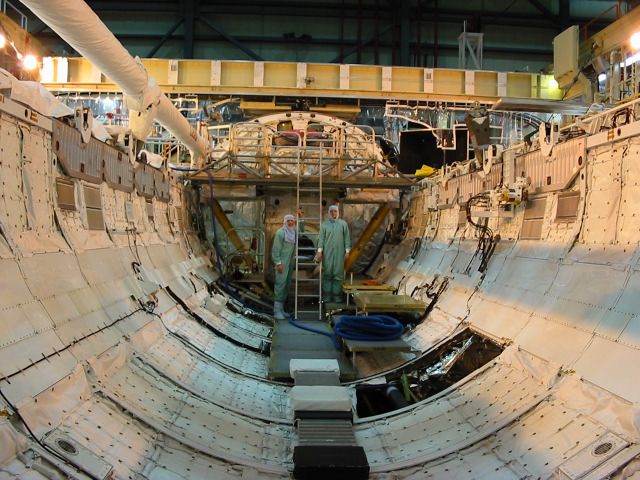
40 work hours. Inspection alone requires hours more for each of the ~32,000 unique tiles on the Orbiter.
Additional protection, while massive compared to payload capacity, would directly impact the critical path
of processing. For instance, the X-33 Advanced Technology Demonstrator program tested metallic Inconel
tiles that proved more robust and more replaceable than Shuttle tiles without severe weight penalties.

Figure 7: The brittle TPS tiles on the Orbiter are highly vulnerable to dents and cracks. Left: one can
  make out impact streaks along the flow path and cracking of varying severity on the tiles. Right:
   during processing, discrepancy tags pepper the belly of the Orbiter signifying repairs required.

Automate Testing and Verification
The Shuttle was not designed with testing and verification in mind, hence a great deal of disassembly is
required merely to inspect components of the Orbiter. (Many of these processes create additional damage,
as discussed later on.) Because inspections are done manually, they are largely subjective, and therefore
require multiple people to provide cross-checking (Figure 8). The Quality Assurance (QA) division is
tasked with finding ways to perform inspections in a reliable manner: in some cases, products cannot be
readily evaluated, so work processes must be reviewed instead, a much more difficult practice that accounts
for roughly half of all oversight activities. Following the Columbia accident and revisions of inspection
procedures, QA has found itself swamped with training new hires to review inspection checkpoints, more
than doubling its staff. Automated in-vehicle health monitoring (IVHM) systems could improve the
targeting and consistency of inspections, mitigating these problems.

 Figure 8: The subjective nature of inspections requires teams of people to check each other’s work.
 Left: six people representing different organizations perform the same tactile stiffness test on a tile
    segment. Right: a similar team of six performs a visual examination of an OMS pod element.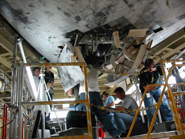
IVHM could also provide new sources of data on component health and performance, with multiple
applications. First, built-in monitoring could potentially allow some verification to be done in flight,
shortening the processing schedule accordingly. Second, such systems would dramatically improve
performance information available to Shuttle engineers, by monitoring components while the vehicle is
operating in its principal design environment. Because few such measurements are currently available,
particularly on the (newer, less instrumented) surviving Orbiters, the engineers “can’t get smarter,” so the
same design uncertainties remain unresolved indefinitely. The Shuttle’s total data handling capacity
currently limits instrumentation upgrades, an item discussed later on.

We mention an example in each of these categories below:

Landing Gear Deployment. The Orbiter landing gear is cycled dozens of times on the ground each flight
for verification, but only once in flight; hence the majority of wear on the system is the product of
processing. Monitoring the operation of the landing gear in flight would allow a more accurate and lower-
impact assessment of its readiness for subsequent flight. (Figure 9)

  Figure 9: The Orbiter landing gear undergoes the vast majority of its cycling on the ground. Left:
 hydraulic lines actuate landing gear during processing. Right: hardware and activities surrounding
   the nose landing gear require dozens of deployment and retraction cycles during a typical flow.

Vehicle Loading. Computational fluid dynamics techniques were not readily available in the 1970s, and
even today are poorly applicable to hypersonic flight regimes. In-flight measurements of loading profiles
would help engineers determine the accuracy of original design margins, and find potentially significant
areas of risk or room for optimization in the structure. Current measurements of loading come from
interpolating ground-based video footage of the Shuttle in flight, a very low-precision technique.

Revise Verification Requirements
Roughly 75% of Orbiter hardware is extracted and replaced in a typical processing flow. The Orbiter
contains 83,402 line replaceable units (LRUs), of which only 3079 are consumables. 5392 of the LRUs are
shop replaceable units (SRUs), requiring servicing at an external facility, such as the NASA Shuttle
Logistics Depot (NSLD). Roughly 2400 of the LRUs are reparable (the rest are replaced outright); 411 of
these are considered “maintenance-significant items,” a special designation granted to hardware requiring
extensive refurbishment. However, a great deal of Orbiter hardware is removed principally for inspection
and testing.

Verification requirements for Orbiter components are generally specified in terms of flight time or total
time between inspections. These schedules usually derive from failure mode predictions, i.e., the
consequences of breaking a requirement, but failure probabilities are difficult to characterize for two
reasons: first, a lack of data on component failures; second, a lack of failures themselves.
The first issue may be addressed through better in-vehicle health monitoring, as discussed above. The
second issue derives from the current practice of eliminating potential failures before they occur. While this
practice is highly advantageous in the realm of catastrophic failures, it deprives the program of valuable
information about non-catastrophic failures and prevents informed tightening of the inspection process.
Some examples follow:

GPS Receivers. Like many systems on the Orbiter, the GPS system employs both secondary and tertiary
redundant backups. Even if all three operate flawlessly throughout the flight, all three are rechecked and
refurbished again before the next flight. This prevents gathering any data on mean time between failures
(MTBF), potentially a basis for revising the inspection requirement. This seems unnecessary with triple
redundancy, and begs the question: “Can we trust what we just flew?”

Airframe. The mass driver for the airframe is not structural loading, but thermal stiffness. Several
engineers believe the airframe was overdesigned in this regard, and could have been tested with lower
margins without catastrophic failure and reinforced as necessary through subsequent modifications.

Start from Standard Parts and Processes
The Space Shuttle was designed largely from the ground up, generating part specifications based on the
precise requirements derived from performance objectives. As a result, most components of the Shuttle are
highly specialized, used nowhere else. Even commercial parts with appropriate specifications undergo
NASA requalification. While this practice in principle provides high precision and low risk, even these
gains may not be universal; and the disadvantages loom large.

The uniqueness of components demands close relationships with single vendors or other providers to
manufacture each piece of hardware on the Shuttle. This binds the program to particular vendors, whose
individual turbulence can wag the dog in many directions at once. Changes in business may break the
relationship from the vendor side, changes in quality from the NASA side; in either case, the Shuttle
program must incorporate the component into its own manufacturing at the NSLD, or engage another
vendor in an expensive and time-consuming qualification process.

In the current life of the program, vendors assume tremendous risk for small opportunities in producing
Shuttle hardware. Shuttle supply provides a very low-volume business, and requires enormous overhead;
moreover, it opens vendors to the possibility of investigation if problems arise in connection with their
components. As a result, vendors are reluctant to continue producing Shuttle hardware, and even more
reluctant to start. This translates into higher costs for commercially produced hardware, and strong
resistance to Shuttle upgrades despite major advances in technology.

Unique components also create tremendous overhead for inspection and problem resolution. Unlike mass-
produced parts, failure data is virtually nonexistent for most Shuttle components; with no standards for
comparison, policy dictates that most elements fly like new, unlike even high-performance aircraft. When
unexpected failures occur, NASA must initiate prolonged, expensive studies on its own to discover the
source of the problem, since no other entity has an interest in the failure. In some cases, this divergence
from mainstream industry can actually lead to lower reliability. The following provide some examples of
problems attributable in part to the highly customized practices of Shuttle development:

GPS Receivers. The Shuttle GPS system was modified from a standard military system due to errors
introduced by the Shuttle’s high velocities in flight, though alternative workarounds were available. Not
only did the program end up having to hire military personnel to help maintain the variant system, but it
wound up showing poorer reliability than the more mainstream military receivers. The relationship was
further strained when the military was asked to maintain outdated tactical air navigation system (TACANS)
stations at high expense solely for Shuttle use.
Inkonel Bolts. These structural bolts on the Orbiter have developed a longitudinal “fold” due to changes in
a vendor manufacturing process. After 25 years of flight, they are now required to go through a
requalification process to investigate the deviance from requirements. There is no other source for the bolts.
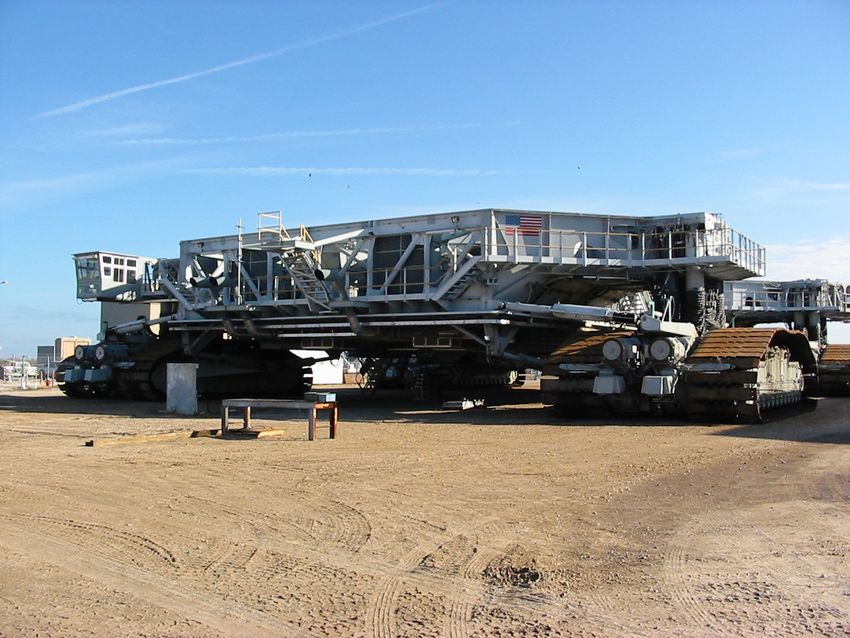
Crawler Shoes. The Space Shuttle Transporter Crawler required replacement tread shoes last year due to
fatigue cracking discovered after decades of wear. Only one foundry in the United States was capable of
producing the new shoes, each made from a ton of specialized molybdenum alloy. (Figure 10)
Figure 10: Only one foundry in the United States could produce the Crawler’s new shoes. Left: the
Crawler’s tread shoes together support 12 million pounds, requiring unparalleled precision
machining and material strength to distribute loads evenly. Right: the new shoes await installation.
Fluid Lines. Cracks discovered in the stainless steel bellows of the Orbiters’ aft fluid lines grounded the
Shuttle fleet during a $100M investigation to determine the cause (engine-induced resonance). They are
now required to be polished to such tight tolerances that “a fly can’t stand on them.”
Ball Joints. The ball strut retention assemblies (BSTRA balls) are very hard ball joints for struts inside the
bellow of engine fuel flex lines. Long-term cracks in these balls also required a $100M investigation.
KU-Band Antenna. The specially developed KU-band antenna is a single-point failure in flight, whose
failure severely compromised one Shuttle science mission. The program considered replacing the failure-
prone antenna with a fixed antenna array, but found the development costs for an additional specialized
component prohibitive.
Can a system with the performance demands of the Shuttle actually be built from standardized,
commercially available parts? NASA and USA engineers answer “absolutely.” Reliability can be achieved
through redundancy and well-calibrated inspections based on the data regularly available for mass-
produced parts. The only challenge is designing the vehicle with available off-the-shelf components in
mind. (Engineers noted one advisable exception to this paradigm: off-the-shelf software, which often
requires extensive modification to meet the needs of a specialized program.)
Design for Servicing
Poor design can make processing activities far more difficult than necessary, stretching schedules and
creating damage leading to further processing requirements. By some estimates, over 70% of Shuttle
processing work is unplanned, about 10% of this attributed to damage and accidents during the processing
activities. As one engineer put it, “we’re our own worst enemy.”Increase Accessibility
Several major sources of damage are related to restricted access for technicians operating the Orbiter. Parts
optimized for flight loading often cannot withstand minor offences unwittingly committed by servicing
personnel in an effort to get where they need to go. Improved accessibility is the most consistent request
heard from technicians and engineers alike. A few examples stand out:
Structural Support Tubes. The boron-aluminum tubes providing major structural support to the airframe
are highly optimized for tension-compression loading, and thin enough to buckle at the slightest lateral
pressure. They must be inspected and often replaced if they are bumped during processing. (Figure 11)
Figure 11: Boron-aluminum support tubes buckle when bumped during processing. Left: technicians
crawl inside the Orbiter midbody through panels like the one at lower right. Right: they can easily
bump against structural support tubes like the green one at lower left.
Wiring. The Orbiter contains ~180 linear miles of wiring, which received low priority in component
geometry decisions. Contrary to design practice, the placement of wires is critical to servicing, where they
must ideally be accessible for repair and yet invulnerable to damage. Due to Kapton insulation embrittled
by ultraviolet radiation, impacts to wires can create short circuits vulnerable to runaway arc tracking; three
such incidents have occurred in flight, generating serious failures. Yet technicians must often stand on
wires to perform other tasks, and many components scrape wires during removal and reinstallation due to
arbitrary placement (Figure 12). Moreover, every other system impacts wiring, multiplying the electrical
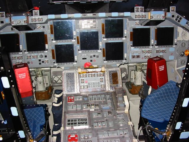
servicing requirements, particularly during major modifications like the cockpit upgrade (Figure 13).
Accumulated wire repairs require careful tracking to avoid excessive risk of shorts, such as might be
introduced by multiple splices on the same wire (Figure 14). Last year saw 2832 discrepancy reports on
wiring alone, each requiring several hours of processing.Figure 12: Awkward placement makes wires vulnerable to flight-critical damage. Left: wires in the
midbody can be impacted by personnel or the equipment they are moving. Right: middeck avionics
boxes routinely scratch or fracture Kapton wire insulation during removal and replacement.
Figure 13: Repairs or modifications to any electrical system impacts wiring in the Orbiter. Left: the
digital cockpit upgrade required tremendous electrical modifications to support new systems. Right:
this required modifications to vehicle inter-segment electrical connections in difficult locations.
Figure 14: Performing and managing wire repairs creates enormous process overhead. Left:
numerous techniques repair or counteract wire damage in different situations. Right: recording,
tracking, and controlling these repairs require extensive operations and information systems.Fuel Cells. The Orbiter’s fuel cells provide its primary power supply, and must be located in the midbody
to avoid excessive voltage drops to fore or aft at 28 VDC (Figure 15). Located underneath a shelf in the
belly of the Orbiter, they require specialized cantilever cranes to lift them in and out. Due to placement of
other components, each of the three fuel cells requires a different crane (see next section).
Figure 15: The Orbiter’s three fuel cells present a major challenge for removal and replacement.
Left: the fuel cells reside beneath a shelf in the forward midbody, bottom left. Right: each requires a
separate crane, strong and maneuverable, for extraction and reinstallation.
Secondary Connectors. Connectors require a secondary engagement mechanism to ensure binding during
flight. One type of connector-saver (Figure 16) is used on the backs of avionics boxes in the middeck, often
requiring technicians to install them inside hollow tubes using a prosthetic pole. This arrangement makes it
difficult to ensure the connector has tightened the full 0.128 inches from contact to a complete mate.
Figure 16: High-precision connector-savers present awkward challenges for removal and installation.
Left: a type of multi-pin connector-saver used for avionics boxes. Right: an engineer illustrates how
connectors reside inside hollow tubes, requiring fine manipulation using prosthetic poles.Middeck Flight Seats. Accessibility can be impaired by personnel hazards as well as awkward geometry.
The seats in the crew module were recently redesigned to save weight (from 92 to 48 lbs), but their attach
fittings now protrude from the floor, creating a tripping hazard inside the midbody during removal and
replacement; tripping while carrying a chair could cause serious injury. (Figure 17)
Figure 17: The modified flight seats create tripping hazards obstructing access in the middeck. Left:
the new seats’ attach fittings protrude from the floor, unlike the earlier design. Right: during most
operations, these can be covered with floor plates, but not while moving the seats themselves.
Eliminate or Standardize Servicing Interfaces
Reduction and re-use of servicing equipment and procedures can dramatically impact the marginal
overhead factor associated with operational infrastructure and logistics. Such gains may be accomplished
by eliminating unnecessary interfaces between components and ground support, and standardizing those
that remain. Eliminating bad interfaces or interface modes can also save mistakes in processing. Examples
abound:
Excessive Connectors. Fluid and electrical lines running through the Orbiter were designed with little
regard for the prolificity of segment interconnects, each of which requires care, repair, and testing during
processing. Minimizing the number of segments in flow lines would strongly impact their expense.
Cold Plate Lifters. Not only do the cold plates for avionics boxes require awkward care during removal
and replacement, but in addition, different cold plates require different lifters to accomplish the transfer.
Standardizing plate and box interfaces would reduce equipment and hassle.
Power Supplies. The Orbiter’s two flight TACANS units come from different vendors; one runs on DC
power, the other on AC power, hence requiring connections to both busses, and thus more wiring. The
difference is entirely unnecessary, considering that the latter unit converts to DC internally.
Distinct Vehicles. Different Orbiters exhibit key differences due to both design changes and divergence
through processing. Many differences require separate sets of ground support equipment (GSE): for
instance, the distinct tile grid patterns on the different vehicles require separate mold libraries and tracking
systems; the unique forward reaction control systems maintain separate processing accessories; and many
developmental systems on Columbia required even more customized GSE.
RSB Drive Gears. The gears on the Rudder/Speed Brake (RSB) admit two possible modes of installation;
the incorrect mode significantly undercuts the designed load tolerance on the RSB. Its backwards
installation was only recently discovered after decades of flight. (Figure 18)Figure 18: The Rudder/Speed Brake (RSB) gears were installed backwards for decades, with potential performance impact. Left: the two rudder panels fan outward symmetrically from the tail interface visible here to provide braking. Right: the gears operating the panels, seen from the rear. Remove Conflicts Between Servicing Tasks The tight integration of the Orbiter and its processing facilities makes coordination of servicing tasks a veritable nightmare. One might expect that procedures on distinct components could be carried out largely in parallel; however, some types of service operations impact or halt major subsets of operations, as most components remain bound together in the Orbiter Processing Facility (OPF) during a flow. Anticipating and avoiding these conflicts could shave precious time from the flow schedule. Power Status. Orbiter power up/power down features most prominently of all constraints on OPF activities. Some procedures require power to be activated to operate subsystem equipment (e.g., thruster removal and antenna deployment); some require power to be deactivated for safety reasons (e.g., wire and multiplexer replacement). A finer division of power supplies could allow more flexibility in parallel processing. Toxic Chemicals. Operations with the potential to release toxic liquids or vapors often require “area clears” of the OPF during which other work grinds to a halt. The most prominent examples are hypergolic fuels, used in the Orbital Maneuvering System (OMS) pods and forward reaction control systems (FRCS), which are removed and replaced during each flow. In addition, all personnel are required to receive training in handling various toxic chemicals, a major cost to operations. Additional equipment is required to guard against safety hazards even when dangerous components are in stasis. Separating operations on these components between facilities could provide one approach to this problem. (Figure 19)
Figure 19: Hazards from isolated components impact all processing activities in the OPF. Left:
 Removal and replacement of OMS pods requires clearing the OPF; after reinstallation, covers and
  desiccant tubes (blue) are required to monitor potential fuel leakage. Right: life support bottles
  provide emergency breathing air for personnel working inside the Orbiter during an accident.

High-Energy Radiation. X rays are used for many kinds of damage inspection, and require clearing or
shielding surrounding areas to reduce risks to personnel.

Component Geometry. Elements of the Orbiter transition among multiple configurations during the
processing flow, providing or limiting access to other elements. Sometimes particular configurations
require substantial support equipment, as in the case of the enormous strongbacks used to support the
payload bay doors when open.

Develop Servicing Procedures with Design
Concurrent development of design and operations is an overarching recommendation of this paper;
however, this section is meant to illustrate the more specific impact of modifying operations procedures
after the design is largely locked down. These examples represent seemingly unavoidable changes
mandated by critical elements missing from the original concept of operations. In aircraft development, the
“system repair manual” is developed in conjunction with the vehicle; this produces far superior results
compared to post facto development. Such integrated, systematic development also improves the quality of
servicing documentation, largely due to an increased recognition of purpose and the involvement of
original designers.

Ascent Debris Management. The flurry of changes precipitated by the Columbia accident investigation
has generated enormous turbulence in operations related to Orbiter ascent debris (things falling off the
Shuttle). New imagery requirements called for opening the OPF bay doors on a cold night to take
electromagnetic baseline imagery for launch cameras; in addition, the launch imagery upgrade to HDTV
will require extensive analysis and interpretation to account for all phenomena previously unobserved with
lower-quality footage. Meanwhile, a lengthy research program has been initiated through the Southwest
Research Institute to construct specifications of allowable limits on different debris types as a function of
altitude. At the same time, foam application procedures have been modified for new External Tanks (ETs),
eliminating the bipod ramp foam that proved dangerous in earlier missions and adding new heaters for ice
prevention; this will require modifying existing ETs in storage, and changing inspection procedures. Even
more drastic measures are now being examined to limit foam shedding, including binding agents, hypelon
painting, and “shrink-wrapping,” any of which would stir up a whirlwind of performance and processing
issues. These debris management activities might have been addressed during design, but were largely
neglected at the time. (Figure 20)
Figure 20: Operational changes dealing with ascent debris have impacted many sectors of Shuttle
 processing. Left: bipod ramp foam breakaway on STS-112 [Credit: CAIB]. Right: the new ET-120
             incorporates modified components to limit foam shedding [Credit: NASA].

Dynatube fittings. Fluid fittings on the Orbiter called “dynatubes” are made of stainless steel polished to
very fine tolerances. Even slight damage to these fittings can cause leaks, which can be detected only by
deploying a mass spectrometer to search for gas traces in the surrounding air. Had leak monitoring been
considered in the design, a much lower-impact solution might be feasible.

Design for Disposal
Often the most neglected servicing operation is the last: discarding system components no longer needed.
Interactions with the outside environment sometimes require additional measures for handling disposal or,
conversely, introduce unanticipated constraints on the operation of the system.

Solid Rocket Fuels. The highly toxic particulates expelled from the Solid Rocket Boosters (SRBs) coat the
entire Mobile Launch Platform (MLP) and surrounding areas following a launch, and contaminate the
water of the thermal reservoir in addition to the platform flush water. None of this water can be reused or
released to natural reservoirs, but instead must be loaded into large fleets of trucks for safe disposal at
remote hazardous waste sites. Alternative designs might have provided better containment of fuel residues.

External Tank. Designers naturally view the ocean as a large, relatively uninhabited, circumplanetary hole
in the ground, perfect for discarding an ET from almost anywhere above the Earth. However, constraints of
safety and diplomacy have limited the ET ditch area to a relatively small patch of the Indian Ocean. This
restriction significantly reduces flexibility in launch trajectories, and impacts liftoff capacity and launch
windows (particularly for missions to the International Space Station: when one such launch experienced a
main engine cutoff three seconds early, nearly all available margin was consumed). Realization of these
issues might have suggested changing the reentry characteristics of the ET or carrying it to orbit.

Modernize Information Systems
Rocket technology has not advanced much since the inception of the Shuttle program, but information
technology has revolutionized nearly every technical enterprise. Because the Shuttle’s operational
requirements have not changed appreciably over the past few decades, it has experienced fewer
opportunities for iterative modernization than other, more dynamic organizations. NASA and USA
employees of all capacities suggested improvements to information systems that could improve Shuttle
processing.
Extend Software Capabilities Modern software can automate much more information manipulation than currently realized, through higher-level representations of data and slightly more sophisticated algorithms. The tedium of human involvement in repetitive, mechanical tasks not only saps valuable time, but reduces morale and creativity within the organization. Some particularly high-impact applications: Task Scheduling. Current scheduling software can encode serial linkages between tasks (A must follow B), but does not incorporate resource availability or other task conflicts, including availability of personnel. Instead, engineers and technicians must recognize these constraints and manually adjust task schedules accordingly. It is not a one-time process: frequent anomalies require readjusting the task schedule at the beginning of every shift, based on progress reports from the previous shift. Some quotes from a USA scheduling meeting demonstrate the routine problems with this approach. First, hastily generated written progress reports foster ambiguity: “I can’t tell what these guys did last night … what happened.” Second, human constraint management is error-prone: “We scheduled a job we can’t work … wouldn’t be the first time.” Even when manually generated schedules are valid, they are unlikely to be optimal: humans cannot effectively search large, complex option spaces without computational assistance. One-time encoding of resource and configuration requirements for planned events, with real-time updates for unplanned ones, would allow dynamic scheduling to be performed by suitably enabled software, substantially reducing these persistent problems. Drawing Management. Engineering drawings are a universal headache for Shuttle engineers, but some simple extensions of drawing tools could ease much of the pain. Some systems in use today do not accept incremental changes, requiring complete duplication in order to maintain the historical record; this makes modifications more cumbersome, and discourages drawing maintenance. Systems like CATIA provide this simple yet valuable functionality. Another requested capability is intelligent numbering, whereby components’ numerical codes automatically reflect useful data like the project, assembly, and part number. This simple automated utility would also save time and energy in drawing management. Replace Communication Tools and Methods Small organizations may accrue few benefits from deploying and maintaining more sophisticated communication tools, but beyond a relatively low size threshold their benefits can be enormous. The Shuttle program still relies on some strikingly anachronistic practices that have been widely replaced in the large technology-driven companies of today. Some key investments in this area could create huge savings: Operations Documentation. Several engineers I observed at KSC appeared to devote large fractions of their daytime work hours to carrying paper documents between offices, floors, and buildings to obtain the signatures required for closure on various procedures. In many cases, these signings involved negligible discussion, so even face-to-face contact provided no additional value. One USA engineer estimated that a typical flow involves ~50,000 separate documents, roughly half of these requiring additional NASA signatures. The impact of this practice goes beyond absolute time spent going places and seeking people: it lowers the overall “tempo” of the organization, and reduces the natural frequency of task completion from minutes to hours or days. Paper-induced inertia also hurts institutional morale. NASA has recently begun experimenting with “change management express” software to digitize processing and signing; while certainly a step in the right direction, it is still catching up with the rest of even the aerospace world: for example, the Boeing C-17 program used a predominantly paperless system throughout, to great effect. The more universal and integrated these measures become, the more effective they will be. (Figure 21)
Figure 21: Paper documents abound wherever work is done. Left: the OPF floor—technicians and
engineers process piles of forms beneath the Orbiter. Right: the Shuttle Tile Facility—every part, no
 matter how small, travels with its own documentation. Many other documents travel on their own.

Technical Discourse. Teleconferences have remained the primary means of technical discussion for NASA
and USA engineers since the birth of the program. Engineers joke about them as the “trailing edge of
technology,” with good reason: the serial flow of telephone conversations tends to send issues in circles,
leaving moderators little ability to organize and unify presented information. This limitation not only slows
real communication, but may affect the ultimate quality of results, since moderators tend to wrap up
decisions with the most recent discussion closer to mind. Teleconferences also make poor use of personal
attention: though individuals can plan partial attendance based on published agendas, the meetings’
inherent fluidity still leaves them sitting in on many talks irrelevant to their own issues. More focused and
flexible systems, such as shared web pages for specific topics, could provide a better means to dynamically
organize information and target engineers’ mental energy.

Streamline, Standardize, Synthesize
Staff at KSC devote a tremendous amount of time to using information systems, hence improved efficiency
in these areas can generate tremendous savings. Suggested improvements generally associate with one of
three major approaches: streamline—reduce the time required to perform a given data manipulation;
standardize—use common formats for the same data across different systems; and synthesize—combine
systems containing the same data into a single system wherever possible. These approaches could be
particularly useful in the following application areas:

Data Reporting. Many software reporting systems incorporate redundant process data, which must be
manually entered into multiple systems in different formats by engineering staff. One example is the PITA
and ELOG systems used in the electrical division, which could be at least partially combined. Separate but
redundant systems within different divisions can also create authorization barriers, and should be avoided.
Data collection systems could also be more unified throughout the program, so that all data sources
generate the appropriate formats from the outset. The Lockheed-Martin Atlas V program illustrates the
impact of standardized data systems, with an estimated ~40% cost savings over comparable programs.

Component Logistics. Tracking and inventory management for both parts and equipment could benefit
from a number of modern technologies. Universal bar code or radio frequency identification (RFID)
tagging could help with locating, moving, and storing components, as used by military programs and
companies like WalMart. Some other automation technologies have already made substantial
improvements to logistics operations (Figure 22). In addition, some past programs have allowed multiple
specifications for identical materials and commodities (e.g., isopropyl alcohol), multiplying costs of
purchasing, tracking, and storing; combining specifications would eliminate these redundancies.
Figure 22: Automation technologies have substantially streamlined parts handling in the logistics
 warehouse. Left: forklifts and other vehicles follow magnetic aisle guide strips and shelf geometries.
 Right: a robotic fetcher handles small parts independently via an access port at the end of the aisle.

Configuration Control. While most data handling functions require simply read-only repositories,
configuration control presents the further challenge of synchronizing dynamically updated state information
across the program. The timeliness and accuracy required of such information—both to save effort and
prevent mistakes—would make program-wide standardization of configuration control systems particularly
valuable.

Capture Institutional Knowledge
All the enhancements of information systems suggested above will help to encode more institutional
knowledge in persistent, usable forms; however, in some cases, dedicated measures may be necessary to
mitigate critical information loss in the life of a large vehicle program. Experiences from the Shuttle point
to two danger areas:

Brain Drain. Senior NASA and USA engineers recall a few key periods during which the program
experienced major turnover in technical staff. The most dramatic such “brain drain” now appears imminent:
the people who began the Shuttle program as young graduates are now reaching retirement. With them will
transpire a great deal of perspective accumulated from working with the program since inception. Though
difficult to measure, most believe the effects will prove significant. More clear and comprehensive records
describing design history and decision logic could help compensate for the transience of individuals.

Engineering Drawings. The original Shuttle drawings have not generally been updated to reflect design
modifications. Because the contractors own the drawings, NASA has no leverage to control their
maintenance. Following the Columbia accident, the program planned a system-wide overhaul of drawings
in accordance with CAIB recommendations; however, this plan was dropped for lack of the estimated $12
million in required funding. The lack of current drawings hampers engineering analysis and processing
activities to this day, an obvious target for change in future programs.
Replace Some Key Technologies
The Shuttle was developed to take advantage of many cutting-edge technologies and hardware of its time in
a wealth of engineering disciplines. Several of these techniques and components have proven problematic
in more or less unanticipated ways, and should be reconsidered for future applications, independent of more
systemic issues of design methodology. Some examples:

Galvanic Couples. Many pairs of metals placed in contact with each other will form galvanic couples,
which gradually lead to chemical breakdown. The Orbiter exhibits ubiquitous galvanic coupling between
metal parts, leading to extensive corrosion requiring constant inspection and maintenance. Such cases
should be largely avoidable with careful design.

Kapton Insulation. One of the largest issues in Shuttle processing, breakdown of Kapton wiring insulation
(due partly to ultraviolet radiation and atomic oxygen exposure) leaves it vulnerable to arc tracking,
wherein the insulation carbonizes to a conductive state. Carbonized Kapton has a resistance of ~10 ohms,
which on a ~30-volt power supply leaves it just below the current limit on the Orbiter’s circuit breakers,
allowing short circuits to persist, particularly between feed and return lines that often run together. The
insulation becomes brittle over time, after which impact or flexing can easily cause shorts, leading to
further degradation and arc tracking. Arc tracking is responsible for failures on at least three flights,
including two Main Engine Controllers on STS-93, which could potentially have led to a double main
engine shutdown and subsequent loss of vehicle; it was investigated as a possible cause of the Columbia
accident. Though Kapton combines many desirable properties, military systems no longer use it for
electrical insulation; other compounds such as Teflon hybrids may prove more suitable for future vehicles,
though replacing the ~150 miles of Kapton insulation in each Orbiter is no longer feasible. (Figure 23)

    Figure 23: Kapton wiring insulation creates major risks of short circuits in Orbiter electrical
systems. Left: arc tracking damage can lead to shorts in surrounding wire bundles. Right: bundles of
 Kapton wiring pervade the Orbiter, often in remote locations like this wing interior. [Credit: CAIB]

Data Lines. Some of the wiring burden derives from the use of dedicated lines for data transfer throughout
the Orbiter. More modern vehicles (and other systems) use data busses to merge data handling into a few
combined electrical lines, significantly reducing overheads associated with wiring. One engineer suggested
an arrangement “like a motorcycle,” with one CPU each at prow and stern and a single universal data bus
in between.

Secondary Fasteners. Shuttle requirements mandate secondary mechanisms to verify torque and locking
on structural fasteners, an area presenting unanticipated challenges. One common method is self-locking
nut plates, which provide additional locking friction in the final tightening of the fastener. However, these
exhibit a number of problems: first, they wear down, losing their self-locking feature after 5-7 fastening
cycles; second, they must be riveted into the structure, often in blind locations; and third, their rivet holes
enlarge and lose strength with each removal and replacement during servicing. Many structures engineers
currently advocate an alternative approach known as “locktight,” a coating placed on threaded fasteners
that hardens to bind them after mating; this approach was not certified with the original design, and has
hence proven difficult to put into service.
Fluid Connectors. The Shuttle currently employs fluid connector fittings with low tolerance to damage or
misalignment. Their small pins reduce the size of connectors, but greatly increase the risks of hang-up and
separation; they are also highly susceptible to damage and corrosion. Pneumatic connectors show persistent
leaks, and some require laser polishing to meet acceptable tolerances. Many engineers have suggested other
types of commercially available fittings (such as KC fittings), which are more damage-resistant, easier to
engage, and more robust to leakage in misalignment.
Flex Hoses. Orbiter flex hoses generally consist of metal bellows with braided stainless steel overwrap.
When bent to a particular radius of curvature, their tension-compression cross-section flattens and the
resulting stress spikes cause cracking. They are also susceptible to fatigue from low-frequency resonances
during transport. Their braided overwrap tends to collect moisture, leading to corrosion which traps
contaminants, creating a difficult cleaning chore. All these problems could be mitigated by working with
stiff stainless steel tubing rather than flex hoses.
Solid Rockets. The impact of solid propellant hazards and their secondary ramifications has been
consistently underestimated. The Shuttle program has routinized solid rockets to unprecedented levels (a
visiting engineer from the Russian Space Agency ran from the VAB at the sight of fueled booster segments
on the floor). Infrastructure for processing, cleaning, testing, and repair requires extensive built-in safety
measures. Toxic particulates require clearing areas during certain procedures and even yet contribute to
some occupational health problems. Anomalies associated with the Solid Rocket Boosters (SRBs) tend to
create major schedule upsets. During transport, the boosters require extensive protection from sources of
electrostatic discharge, such as lightning. As mentioned earlier, their exhaust toxifies wastewater from each
Shuttle launch; moreover, their propellant grain penetrates the MLP blast shield, destroying cables inside
the launch service towers. In the final analysis, though motivated by the promise of reusability, the SRBs’
refurbishment costs have proven comparable to the costs of pure replacement. Their substantial risks have
led USA engineers to recommend against using solid propellant devices wherever possible. (Figure 24)
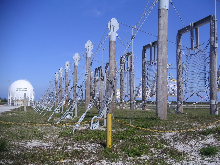
Figure 24: The hazards associated with toxic, explosive SRB solid propellants reach far and wide.
Left: facilities handling fueled boosters, like the VAB, must take special precautions to avoid leakage
or ignition. Right: the booster discharge destroys cables in launch service towers (one shown at left)
and contaminates the wastewater flushing the MLP at launch (pipes at center and bottom).
Thermal Protection System. The litany of issues associated with the Orbiter thermal protection system
(TPS) derives in part from a key design decision: the separation of the TPS from the airframe. The tile
system was expected to work something like a jigsaw puzzle, with tiles snapping in and out as needed; theairframe architecture contributed to the failure of this concept in multiple ways. First, the differential
thermal expansion of the airframe and TPS necessitated high-precision gaps between TPS tiles, driving up
the costs of tile inspection and replacement. Second, thermal cycling led to tile cracking and slight
perturbations of the tile grid on every flight, a major contributor to processing requirements. By contrast,
the X-33 design made the TPS and airframe one and the same, eliminating this fundamental problem.
Figure 25: Interactions between the separate TPS and airframe cause many of the problems
afflicting the tile system. Left: the gaps required to accommodate differential thermal expansion
necessitate manually measuring super-fine tolerances on tile geometry. Right: because of grid shifts,
tiles change shape between flights, hence their molds must be iteratively modified at each repair.
Plan Programs, Not Vehicles
Much more than in other industries, design in aerospace has traditionally focused on individual products
(often vehicles) rather than long-term support for particular capabilities. This may be partly attributed to the
relatively large scale and expense of these individual products in the aerospace sector. However, this
practice can impair the cost-effective achievement of underlying programmatic goals. In particular, it
reduces the frequency of product iteration far below that of most other industries, creating numerous
technical and organizational issues. More iterative, globally focused programs could mitigate these
problems; in particular, they could:
Increase Operational Feedback to Design
As we have seen, anticipating the operational impact of design decisions can be quite challenging, despite
great effort. In the words of one NASA engineer, “as a designer, you only have so much time to figure out
how to do it all right.” As the first reusable space vehicle, very little knowledge gained from operating the
Shuttle has ever been exploited to design another such vehicle. At the same time, feasible design changes to
the Shuttle itself are small, few, and far between: merely beginning the Engineering Order process can cost
upwards of $10K. This suggests Frederick Brooks’ famous maxim: “Plan to throw one away.” There will
never be a complete substitute for significant design changes based on feedback from the field. Some
examples:
Structural Optimization. Due to the complexity of structural analysis and lack of relevant flight data, the
Orbiter’s original structure and layout suffers from many suboptimalities. The inertial configuration of the
vehicle (CG placement, etc.) proved poorly estimated, ultimately leading to the removal of useful front-
wheel steering (to save nose weight) and common use of wasted ballast for payload balancing. Meanwhile,
loading tolerances were often pessimistic: while a few components have been replaced to save mass (such
as the heavy rear “flipper doors”), most structural elements are too highly integrated into the airframe to be
practically modified. Redesign with better data and improved technology would allow substantial
corrections to these deficiencies.You can also read