BURKE LAKEFRONT AIRPORT (BKL) - Prepared By
←
→
Page content transcription
If your browser does not render page correctly, please read the page content below

BURKE LAKEFRONT AIRPORT (BKL)
Airport Layout Plan (ALP) Update Narrative Report
 WORKING PAPER #1: INVENTORY & FORECASTS
                    May 2021

                                            Prepared By: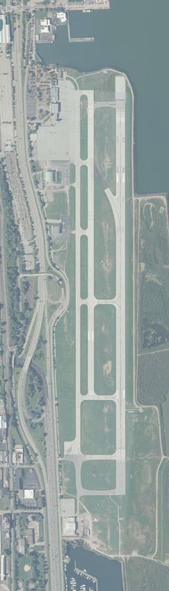
AIRPORT LAYOUT PLAN (ALP) UPDATE NARRATIVE REPORT // Burke Lakefront Airport

TABLE OF CONTENTS

 1.1       Project Description .................................................................................................. 1-1
   1.1.1      Public and Stakeholder Involvement Program.................................................................. 1-2
 1.2       Airport Background.................................................................................................. 1-2
   1.2.1      Location and Study Area .................................................................................................. 1-2
   1.2.2      Airport Role ..................................................................................................................... 1-4
   1.2.3      Airport Tenants ............................................................................................................... 1-5
   1.2.4      Confined Disposal Facilities.............................................................................................. 1-6
 1.3       ALP Update Narrative objective ............................................................................... 1-7
 1.4       Airside Facilities ....................................................................................................... 1-8
   1.4.1      Airport Design Criteria ................................................................................................... 1-10
   1.4.2      Runway System ............................................................................................................. 1-11
   1.4.3      Taxiway System ............................................................................................................. 1-13
   1.4.4      Aircraft Parking Aprons .................................................................................................. 1-14
   1.4.5      Airfield Markings ........................................................................................................... 1-15
   1.4.6      Airfield Signage.............................................................................................................. 1-16
   1.4.7      Navigational Aids (NAVAIDs) and Instrument Procedures .............................................. 1-17
   1.4.8      Airfield Lighting ............................................................................................................. 1-20
   1.4.9      Airfield Pavement Condition .......................................................................................... 1-20
   1.4.10 Airspace Obstructions .................................................................................................... 1-21
 1.5       Airport Buildings and Infrastructure....................................................................... 1-22
   1.5.1      Terminal Facility ............................................................................................................ 1-22
   1.5.2      Airport Equipment Storage and Maintenance / Aircraft Rescue and Firefighting (ARFF) . 1-23
   1.5.3      Air Traffic Control Tower (ATCT) .................................................................................... 1-23
   1.5.4      General Aviation (GA) Facilities...................................................................................... 1-24
   1.5.5      Aircraft Fueling .............................................................................................................. 1-24
   1.5.6      Airport Service Roads .................................................................................................... 1-24

 2.1       Introduction............................................................................................................. 2-1
 2.2       Airport Categorization ............................................................................................. 2-1
 2.3       Forecast Rationale ................................................................................................... 2-2

May 2021 DRAFT                                                                                                 Table of Contents                   i

AIRPORT LAYOUT PLAN (ALP) UPDATE NARRATIVE REPORT // Burke Lakefront Airport

   2.3.1      Factors Affecting Forecasts .............................................................................................. 2-3
   2.3.2      Forecast Data Sources ..................................................................................................... 2-5
   2.3.3      Forecast Categories ......................................................................................................... 2-7
 2.4       Socioeconomic Data ................................................................................................ 2-8
   2.4.1      Population ....................................................................................................................... 2-8
   2.4.2      Personal Income per Capita ............................................................................................. 2-9
   2.4.3      Employment .................................................................................................................. 2-10
 2.5       Historical Aviation Activity ..................................................................................... 2-11
 2.6       COVID-19 Impacts on Aviation Activity .................................................................. 2-14
   2.6.1      Recent Enplanement Trends .......................................................................................... 2-14
   2.6.2      Recent Operations Trends ............................................................................................. 2-16
 2.7       Aviation Activity Recovery Forecasts from COVID-19 ............................................. 2-22
   2.7.1      Enplanements ............................................................................................................... 2-23
   2.7.2      Commercial Aviation ..................................................................................................... 2-31
   2.7.3      General Aviation............................................................................................................ 2-34
   2.7.4      Military Aviation ............................................................................................................ 2-37
 2.8       Aviation Activity Forecasts after COVID-19 ............................................................ 2-38
   2.8.1      Enplanements Forecast ................................................................................................. 2-38
   2.8.2      Operations Forecast ...................................................................................................... 2-41
   2.8.3      Based Aircraft Forecast .................................................................................................. 2-45
   2.8.4      Recommended Forecast ................................................................................................ 2-46
 2.9       Peak Aviation Operations Forecast ........................................................................ 2-47
 2.10      Critical Aircraft ....................................................................................................... 2-49
   2.10.1 Exiting Critical Aircraft ................................................................................................... 2-50
   2.10.2 Future Critical Aircraft ................................................................................................... 2-52

May 2021 DRAFT                                                                                                Table of Contents                   ii
AIRPORT LAYOUT PLAN (ALP) UPDATE NARRATIVE REPORT // Burke Lakefront Airport

FIGURES
Figure 1-1 – Location Map ....................................................................................................... 1-3
Figure 1-2 – Vicinity Map......................................................................................................... 1-4
Figure 1-3– Existing Confined Disposal Facilities ...................................................................... 1-6
Figure 1-4 – Existing Facilities .................................................................................................. 1-9
Figure 1-5 – Typical Declared Distances................................................................................. 1-12
Figure 1-6 – Runway 6L Safety Areas ..................................................................................... 1-13
Figure 1-7 – Existing Taxiways ............................................................................................... 1-14
Figure 1-8 – Apron Areas ...................................................................................................... 1-15
Figure 1-9 – Typical MALSF .................................................................................................... 1-19
Figure 1-10 – National Airspace System................................................................................. 1-22
Figure 1-11 – Terminal Area Facilities .................................................................................... 1-23
Figure 1-12 – General Aviation Facilities................................................................................ 1-24
Figure 2-1 – BKL Location ........................................................................................................ 2-4
Figure 2-2 – BKL Vicinity .......................................................................................................... 2-5
Figure 2-3 – Historic Population Growth Rates ........................................................................ 2-9
Figure 2-4 – Historic Personal Income per Capital Growth Rates ........................................... 2-10
Figure 2-5 – Historic Employment Growth Rates ................................................................... 2-11
Figure 2-6 – Historical BKL TAF Operations by FAA Fiscal Year ............................................... 2-12
Figure 2-7 – Historical BKL TAF Enplanements by FAA Fiscal Year .......................................... 2-12
Figure 2-8 – Historical BKL BTS Enplanements by FAA Fiscal Year .......................................... 2-13
Figure 2-9 – Historical BKL Based Aircraft .............................................................................. 2-13
Figure 2-10 – BKL Total Enplanements .................................................................................. 2-15
Figure 2-11 – BKL Enplanements by Month Before and During Pandemic ............................. 2-16
Figure 2-12 – BKL Total Operations by Commercial and GA ................................................... 2-17
Figure 2-13 – BKL Total Operations by Month Before and During Pandemic .......................... 2-18
Figure 2-14 – BKL GA Operations by Month Before and During Pandemic ............................. 2-19
Figure 2-15 – BKL Commercial Operations by Month Before and During Pandemic ............... 2-20
Figure 2-16 – Ultimate Air Operations by Month Before and During Pandemic ..................... 2-21

May 2021 DRAFT                                                                                        Table of Contents              iii
AIRPORT LAYOUT PLAN (ALP) UPDATE NARRATIVE REPORT // Burke Lakefront Airport

Figure 2-17 – Ultimate Air Enplanements by Month Before and During Pandemic ................ 2-22
Figure 2-18 – BKL Optimistic Enplanement Recovery Forecast .............................................. 2-27
Figure 2-19 – BKL Pessimistic Enplanement Recovery Forecast ............................................. 2-31
Figure 2-20 – Optimistic Commercial Operations Recovery Forecast ..................................... 2-32
Figure 2-21 – Pessimistic Commercial Operations Recovery Forecast .................................... 2-34
Figure 2-22 – Optimistic GA Operations Recovery Forecast ................................................... 2-35
Figure 2-23 – Pessimistic GA Operations Recovery Forecast .................................................. 2-37
Figure 2-24 – Air Service Enplanement Forecast .................................................................... 2-39
Figure 2-25 – Historic Trend Enplanements Forecast ............................................................. 2-40
Figure 2-26 – Econometrics Enplanements Forecast.............................................................. 2-40
Figure 2-27 – Historic Trend Commercial Operations Forecast .............................................. 2-41
Figure 2-28 – Econometrics Commercial Operations Forecast ............................................... 2-43
Figure 2-29 – Historic Trend GA Operations Forecast ............................................................ 2-44
Figure 2-30 – FAA Aerospace 2021-2041 GA Operations Forecast ......................................... 2-45
Figure 2-31 – BKL Annual Operations by AAC D and ADG III Aircraft ...................................... 2-52

May 2021 DRAFT                                                                            Table of Contents           iv

AIRPORT LAYOUT PLAN (ALP) UPDATE NARRATIVE REPORT // Burke Lakefront Airport

TABLES
Table 1-1 – Project Advisory Committee.................................................................................. 1-2
Table 1-2 – NPIAS Airport Classifications ................................................................................. 1-5
Table 1-3 – Airport Reference Code....................................................................................... 1-10
Table 1-4 – Existing Runway Specifications ........................................................................... 1-11
Table 1-5 – Existing Taxiway Specifications............................................................................ 1-14
Table 1-6 – Runway Markings................................................................................................ 1-15
Table 1-7 – Taxiway Markings ............................................................................................... 1-16
Table 1-8 – Airfield Signage ................................................................................................... 1-17
Table 1-9 – Navigational Aids (NAVAIDs) and Approach Lighting .......................................... 1-18
Table 1-10 – Airfield Pavement Condition ............................................................................. 1-21
Table 2-1 – NPIAS Airport Classifications ................................................................................. 2-2
Table 2-2 – 2020 BKL Based Aircraft ...................................................................................... 2-14
Table 2-3 – 2020 BKL Based Aircraft (Adjusted) ..................................................................... 2-14
Table 2-4 – BKL Total Enplanements...................................................................................... 2-14
Table 2-5 – BKL Enplanements by Month Before and During Pandemic ................................. 2-15
Table 2-6 – BKL Total Operations........................................................................................... 2-16
Table 2-7 – BKL Total Operations by Month Before and During Pandemic ............................. 2-17
Table 2-8 – BKL GA Operations by Month Before and During Pandemic ................................ 2-19
Table 2-9 – BKL Commercial Operations by Month Before and During Pandemic .................. 2-19
Table 2-10 – Ultimate Air Operations by Month Before and During Pandemic ...................... 2-20
Table 2-11 – Ultimate Air Enplanements by Month Before and During Pandemic ................. 2-21
Table 2-12 – Variables for Aviation Activity Recovery from Pandemic ................................... 2-22
Table 2-13 – Ultimate Air Optimistic Load Factor Recovery Forecast ..................................... 2-25
Table 2-14 – Ultimate Air Optimistic Enplanement Recovery Forecast .................................. 2-25
Table 2-15 – BKL Optimistic Enplanement Recovery Forecast................................................ 2-26
Table 2-16 – Pessimistic Load Factor Recovery Forecast ........................................................ 2-28
Table 2-17 – Ultimate Air Pessimistic Enplanement Recovery Forecast ................................. 2-29
Table 2-18 – BKL Pessimistic Enplanement Recovery Forecast............................................... 2-30

May 2021 DRAFT                                                                                       Table of Contents             v
AIRPORT LAYOUT PLAN (ALP) UPDATE NARRATIVE REPORT // Burke Lakefront Airport

Table 2-19 – Optimistic Commercial Operations Recovery Forecast ...................................... 2-32
Table 2-20 – Pessimistic Commercial Operations Recovery Forecast ..................................... 2-33
Table 2-21 – Optimistic GA Operations Recovery Forecast .................................................... 2-35
Table 2-22 – Pessimistic GA Operations Recovery Forecast ................................................... 2-36
Table 2-23 – Air Service Enplanement Forecast ..................................................................... 2-39
Table 2-24 – Econometrics MSA Employment Commercial Operations Forecast (Adjusted) .. 2-43
Table 2-25 – FAA Aerospace 2020-2040 GA Operations Forecast .......................................... 2-45
Table 2-26 – FAA Aerospace 2020-2040 Based Aircraft Forecast (Adjusted) .......................... 2-46
Table 2-27 – Recommended Forecast Summary .................................................................... 2-47
Table 2-28 – Recommended Forecast vs. FAA 2020 TAF ........................................................ 2-47
Table 2-29 – Historical Peak Month Operations..................................................................... 2-47
Table 2-30 – Historical Peak Month-Peak Hour Average Operations...................................... 2-48
Table 2-31 – Peak Aviation Operations Forecast .................................................................... 2-49
Table 2-32 – AAC and ADG Characteristics ............................................................................ 2-49
Table 2-33 – Applicability of Aircraft Classifications ............................................................... 2-50
Table 2-34 – BKL Operations by AAC Category and ADG Group ............................................. 2-50
Table 2-35 – Design Aircraft Family Fleet Mix Operations by ACC C and D Aircraft ................ 2-51

May 2021 DRAFT                                                                              Table of Contents            vi
AIRPORT LAYOUT PLAN (ALP) UPDATE NARRATIVE REPORT // Burke Lakefront Airport

       INVENTORY OF EXISTING FACILITIES AND CONDITIONS
The City of Cleveland has retained CHA Consulting, Inc. (‘CHA’) to prepare an Airport Layout Plan
(ALP) Update and associated Narrative Report for Burke Lakefront Airport (‘BKL’ or ‘the Airport’).
The purpose of this update is to evaluate how the Confined Disposal Facilities (CDF) impact
existing and future operations at the Airport. This inventory chapter provides a description of the
project and a background overview of the Airport and its existing facilities.
1.1    PROJECT DESCRIPTION
The existing CDF(s), in particular CDF 12 and portions of 9, have raised concerns with the FAA
over the last two years as the Cleveland-Cuyahoga County Port Authority (Port Authority) began
reusing CDF 12 for their dredge material beneficial reuse strategy. The operation of the CDFs has
raised the following concerns that will be addressed through this ALP Update process:
       Property Ownership
       Non-compatible operations and land use within the Runway Protection Zone
       Access Through the Airport Operations Area (AOA) and Runway Object Free Area (ROFA)
       Impacts to the Proposed Replacement Runway 6R-24L
       Impacts on the existing Automated Surface Observation System (ASOS)
In addition to addressing the relationship and impacts the CDF(s) have on BKL, this project will
also update the forecast for aviation demand. Since the last update to the aviation forecasts, BKL
has exceeded 10,000 annual enplanements in 2017, 2018, and 2019. Finally, BKL currently does
not have an FAA approved Exhibit ‘A’ Property Map, which will be completed as part of this
project. Therefore, this ALP Update will complete the following:
       Complete an Exhibit ‘A’ Property Map pursuant to Federal Aviation Administration (FAA)
       Standard Operating Procedure (SOP) 3.00 for FAA Review of Exhibit ‘A’ Airport Property
       Inventory Maps
       Update the 2017 ALP addressing the impacts to the airfield from existing and proposed
       CDF operations.
       Update the aviation forecast demand.
       Complete an ALP Update Narrative Report documenting the changes from the 2017 ALP.
It should be noted that the existing base mapping and 2017 ALP will be utilized in this update.
The collection of new base mapping and obstruction data pursuant to Airports Geographic
Information Systems (AGIS) in accordance with FAA Advisory Circular’s: 150/5300-16B,150/5300-
17C, and 150/5300-18B were not part of this project.

May 2021 DRAFT                              Inventory of Existing Facilities and Conditions     1-1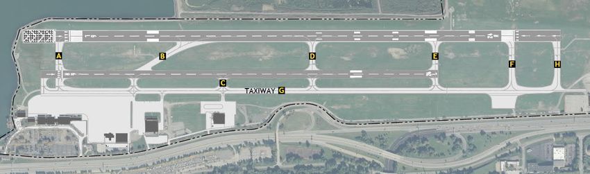
AIRPORT LAYOUT PLAN (ALP) UPDATE NARRATIVE REPORT // Burke Lakefront Airport

1.1.1 Public and Stakeholder Involvement Program
Public and stakeholder involvement is an integral part of any significant airport planning study as
it encourages information-sharing and collaboration among the community and airport
stakeholders that hold a collective interest in the outcome of the study. For the purpose of this
study, a Project Advisory Committee was formed to guide the technical development of the ALP
Update and serve as a local sounding board throughout the process. The stakeholders included
the airport sponsor (City of Cleveland, Department of Port Control), Cleveland-Cuyahoga County
Port Authority (Port Authority), United States Army Corp of Engineers (USACE), the Mayor’s
Office, City Planning, and select Airport tenants. The full list of this committee is listed in Table
1-1.
                             Table 1-1 – Project Advisory Committee
                           Name                                Agency
                  Mr. Edward Rybka         City of Cleveland, Mayor’s Office
                  Mr. Nick Belluardo       City of Cleveland, Department of Port Control
                  Mr. Duncan Bauer         City of Cleveland, Department of Port Control
                  Mr. Robert Kennedy       City of Cleveland, Department of Port Control
                  Mr. Khalid Bahhur        City of Cleveland, Department of Port Control
                  Mr. Dennis Kramer        City of Cleveland, Department of Port Control
                  Mr. Nicholas LaPointe    Cleveland-Cuyahoga County Port Authority
                  Mr. Russel Brandenburg   U.S. Army Corp of Engineers
                  Mr. Tony Campofredano    City of Cleveland, BKL Staff
                  Mr. Joel Woods           City of Cleveland, BKL Staff
                  Mr. Richard DeCarlo      Ultimate Air
                  Mr. Paul Yagel           Signature Flight Support
                  Mr. Raymond Baca         BKL ATCT
                  Mr. Freddy Collier       City of Cleveland, Planning
                  Mr. Mark Molnar          Zone Aviation
                  Mr. Raymond Brown        Top Gun
                  Ms. Nancy Todd           T&G Flying
                  Mr. Richard Newenhisen   Aitheras Aviation Group, LLC
                 Source: CHA, 2021.

1.2    AIRPORT BACKGROUND
Understanding the background of an airport and the region it serves is essential in making
informed decisions pertaining to airport-related improvements. This section discusses BKL, the
context of its location, service area, and its role in the National Airspace System (NAS).
1.2.1 Location and Study Area
BKL is located along Interstate 90, on the shore of Lake Erie, immediately northeast of downtown
Cleveland. BKL is approximately 445 acres and is located on fill under multiple submerged land
leases the City of Cleveland has with the State of Ohio (i.e. State owns the lake bottom and leases
any land filled on top). In addition, various CDFs are also part of airport property.
Given its proximity to these major business centers, the Airport is a key general aviation facility
serving the entire Northeast Ohio region. BKL’s location, regarding time and distance in nautical
miles (nm), in comparison to the region’s other major airports is as follows:

May 2021 DRAFT                               Inventory of Existing Facilities and Conditions      1-2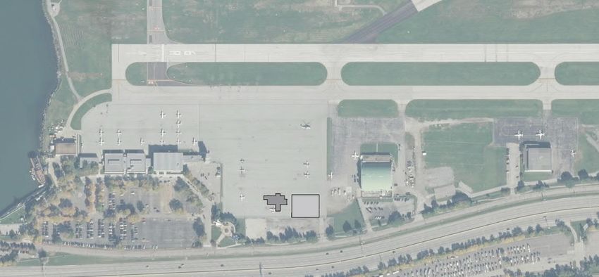
AIRPORT LAYOUT PLAN (ALP) UPDATE NARRATIVE REPORT // Burke Lakefront Airport
Cleveland Hopkins International Airport (CLE) – 9 nm southwest of BKL; approximate 20-
minute drive
Cuyahoga County Airport (CGF) – 9 nm northeast of BKL; approximate 15-minute drive
Akron Canton Airport (CAK) – 38 nm south of BKL; 60-minute drive.
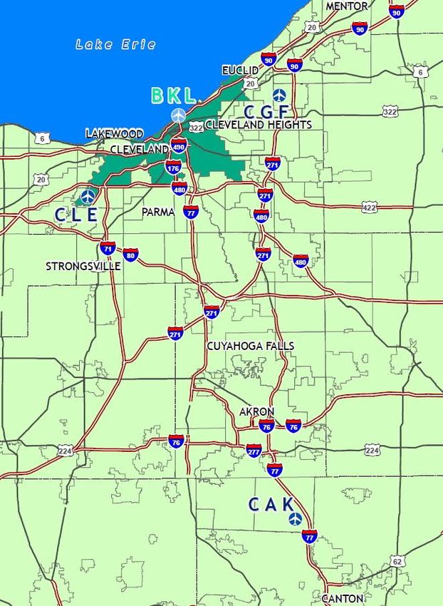
The relative locations of BKL and these airports, as well as the surrounding region, are depicted
in Figure 1-1, with the general vicinity of the Airport within Cleveland depicted in Figure 1-2.
Figure 1-1 – Location Map
Source: CHA, 2021.
May 2021 DRAFT Inventory of Existing Facilities and Conditions 1-3AIRPORT LAYOUT PLAN (ALP) UPDATE NARRATIVE REPORT // Burke Lakefront Airport
Figure 1-2 – Vicinity Map
Source: CHA, 2021.
1.2.2 Airport Role
Airports included in the National Plan of Integrated Airports Systems (NPIAS) are considered
significant to national air transportation and are eligible to receive grants under the FAA’s Airport
Improvement Program (AIP). The NPIAS further categorizes the nation’s airports based on types
of service provided, such as commercial or general aviation services.
In the 2021 to 2025 NPIAS Report, BKL is classified as a National General Aviation airport. Based
on NPIAS criteria, National category GA airports have 10,000+ enplanements and at least 1
charter enplanement by a large certificated air carrier and/or 5,000+ instrument operations, 11+
based jets, 20+ international flights, or 500+ interstate departures. The classification is based on
existing activity levels as shown in Table 1-2.
May 2021 DRAFT Inventory of Existing Facilities and Conditions 1-4AIRPORT LAYOUT PLAN (ALP) UPDATE NARRATIVE REPORT // Burke Lakefront Airport
Table 1-2 – NPIAS Airport Classifications
Hub Type:
Airport Classifications
% of Annual Passenger Boardings
Large Hub:
1% or more
Commercial Service: Primary: Medium Hub:
Publicly owned airports that have Have more than 10,000 At least .25%, but less than 1%
at least 2,500 passenger passenger boardings Small Hub:
boardings each calendar year and each year At least .05%, but less than .25%
receive scheduled passenger Non-hub Primary:
service More than 10,000, but less than .05%
Non-primary Commercial Service:
Nonprimary
At least 2,500, and no more than 10,000
Reliever
Non-primary (Except Commercial Service)
General Aviation
Source: FAA 2021-2025 NPIAS Report
1.2.3 Airport Tenants
As a GA airport with National status, BKL serves a broad range of tenants and operational activity.
This includes, but is not limited to, the following:
Commercial air service: Ultimate Air Shuttle, an on-demand Part 135 operator, provides
scheduled air service 5 days a week to Cincinnati-Lunken Airport (KUK)
General aviation: Given its proximity to major business centers, event spaces, sporting
venues, and other major cultural centers of downtown Cleveland, BKL serves a wide
variety of both transient and based aircraft operators. These are handled through its
fixed-base operator (FBO), Signature Flight Support. Signature handles fueling, hangar
operation, and maintains the FBO Terminal.
Charter flights: In addition to GA activity, charter operations are handled by Aitheras
Aviation and BKL accommodates visiting professional sports teams (NBA & MLB).
Flight training: Multiple flight schools operate and train at BKL, including Zone Aviation,
Circadian Knight Corporation/Top Gun, and T&G Flying. Additionally, the PHASTAR
Corporation is a non-profit organization that trains youth students in flight, through the
Cleveland Metropolitan School District.
Emergency services: Due to its proximity to several world-renowned medical centers,
Cleveland Clinic Critical Transport, and PHI Air Medical provide emergency medical
transport services and are based at BKL. Additionally, the Cleveland Police Department
bases aviation units at the Airport.
Non-aeronautical uses: Space in and around the terminal building is leased out for non-
aeronautical development purposes, such as the International Women’s Air and Space
Museum and office space for private tenants.
May 2021 DRAFT Inventory of Existing Facilities and Conditions 1-5AIRPORT LAYOUT PLAN (ALP) UPDATE NARRATIVE REPORT // Burke Lakefront Airport
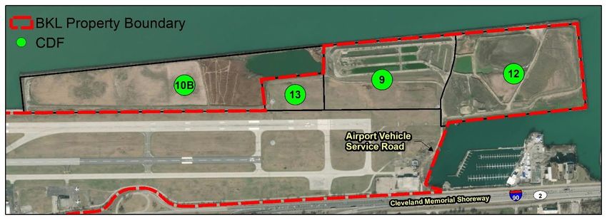
1.2.4 Confined Disposal Facilities
Operating as both a neighbor and a tenant, the CDFs are located both on airport property and
adjacent to airport property. A CDF is a technology where dredged material is placed inside
perimeter dikes that are built up above the water surface level. This provides more protection to
the adjacent surface water as any contaminated material is confined. The dredged material at
BKL comes from the Cuyahoga River. There are currently three CDFs located on airport property
and one adjacent to airport property (see Figure 1-3). The Port Authority currently operates the
northern half of CDF 9 and all of CDF 12, both currently on airport property. The U.S. Army Corps
of Engineers (USACE), Buffalo District operates and maintains CDF 10B, and CDF 13 is closed.
Figure 1-3– Existing Confined Disposal Facilities
Source: CHA, 2021.
CDF 9 served as storage for dredge material from 1969-1974 with a capacity of 2.0 million cubic
yards while CDF 12 served in the same capacity from 1974-1979. The facility cost approximately
$6.8 million and was constructed at 100 percent Federal cost. CDF 12 was designed with an
approximate capacity of 2.8 million cubic yards. The Port Authority was the local sponsor for CDF
12 and the City of Cleveland was the local sponsor for CDF 9.
It was initially anticipated that by the end of 2008, all existing CDF’s in Cleveland would be filled.
The Port Authority, in conjunction with the USACE identified measures to obtain additional and
renewable capacity by operating sediment processing facility within the bounds of CDF 9 & 12.
This sediment processing facility produces manufactured topsoil by dewatering and blending
dredge material which can then be removed from the CDF and used for construction elsewhere.
The space created by this on-going removal of sediment is used to accommodate future dredged
material storage and topsoil production. The Port Authority dredges, recycles, and transfers as
much as 150,000 CY of this material offsite annually with the remaining material permanently
stored in elevated retention basins on CDF 12.
According to previous Construction Safety Phasing Plans (CSPP) submitted to FAA, the removal
of dredge sediment from CDF 9 & 12 occurs throughout the year and is necessary to continuously
restore the CDF’s capacity. The process includes transporting dredge sediment from the
Cuyahoga River to the CDF, where it is dewatered and stockpiled on site. This material is then
loaded out into trucks and removed from the facility.
May 2021 DRAFT Inventory of Existing Facilities and Conditions 1-6AIRPORT LAYOUT PLAN (ALP) UPDATE NARRATIVE REPORT // Burke Lakefront Airport The CDF truck traffic currently utilizes the Vehicle Service Road (VSR) on the east side of the airport accessing the Airport Operations Area (AOA) through a controlled gate and traveling north to enter the CDF. The existing VSR is outside, but adjacent to the Runway 6L-24R Runway Safety Area (RSA). Previously, approximately 200 feet of the VSR traversed the Runway Object Free Area (ROFA); however, the City implemented declared distances for 6L operations in 2020 to temporarily mitigate the non-standard condition, which is discussed in more detail in Section 1.4.2. In addition, approximately 1,520 linear feet of the airport VSR and a portion of CDF are located within the Runway 6L-24R Approach and Departure RPZs. 1.3 ALP UPDATE NARRATIVE OBJECTIVE BKL underwent a comprehensive airport master plan update that was completed in 2017 with the final publication of the BKL Airport Master Plan (APM) Update. As a part of the AMP, an updated ALP depicting proposed future development was developed. A typical master plan outlines the future development of an airport, and includes several components: identification of existing conditions, forecasting, determining facility requirements, developing alternatives, recommending improvements, and developing capital improvement plans and funding mechanisms. It can also include a significant public involvement program. Airport master plans are typically updated by airport sponsors every 10-12 years, and because of their complexity can often take up to two years to complete. An ALP documents the Master Plan’s recommended improvements over time, and as such, is used as a planning and funding tool by the Federal Aviation Administration (FAA) to prioritize and plan for funding of airport capital improvement projects at airports over a 20-year planning horizon. Thus, any airport that uses FAA Airport Capital Improvement (AIP) funding are bound by Federal Grant Assurance 29 under the Airport and Airway Improvement Act of 1982 which requires an airport sponsor keep its ALP updated. The ALP is often updated after a construction project that changes the geometry of the airfield, adds a new building, or the acquisition of land into airport property. Other instances that may require a modification to an existing ALP includes future development shown on the ALP that is no longer considered necessary to meet the forecasted aviation demand or no longer meets updated FAA design criteria. The future development shown on the 2017 ALP was based upon the forecasted need and existing facilities and services that were available at the Airport at that time, which included a new parallel runway outboard of the existing Runway 6L-24R. This new runway allowed the existing in-board runway to be converted into a taxiway which opened the south side of the airport for development. The on-going CDF operations as well as the 20-year plan for the CDF dredge operation impacts this proposed outboard runway. Although the City is fully committed to supporting existing and future aviation activity at the airport, the vision for the airport has shifted to also accommodate the CDF operations, as it also plays a very important role in the economy of the City and Cuyahoga County. This ALP Update Narrative Report provides revised aviation demand forecasts and facility requirements through the next 20 years, reflecting the City’s changes. It assesses requirements for the airfield (runway, taxiways, safety and object free areas, runway protection zones, and navigational aids) and landside (aprons, hangars, vehicle access roads, maintenance areas, and May 2021 DRAFT Inventory of Existing Facilities and Conditions 1-7
AIRPORT LAYOUT PLAN (ALP) UPDATE NARRATIVE REPORT // Burke Lakefront Airport

buildings that are within the City’s control) based on existing conditions of these facilities and
future demand.
The initial step in the airport planning process is to develop an inventory of the existing physical
conditions and operational characteristics of the Airport and its surroundings. The information
presented in this chapter is the basis for evaluating the Airport’s existing and future facility
requirements.
1.4     AIRSIDE FACILITIES
The Airport’s airside and airfield facilities generally include the facilities located within the airport
perimeter that are most closely associated with the movement and operation of aircraft, such as
taxiing, takeoff, landing, and parking. Additional elements related to airfield activity and
infrastructure include the runway and taxiway systems, aircraft parking aprons and hangars, and
airfield pavement, markings, signage, lighting, and NAVAIDs. The existing facilities are depicted
in Figure 1-4.

May 2021 DRAFT                                Inventory of Existing Facilities and Conditions         1-8
SW
                                            AM
                                               P

                          RUNWAY 6L-24R
                                                                                  BURKE LAKEFRONT AIRPORT
                          RUNWAY 6R-24L                             10

                                                                8   9
    TERMINAL APRON

                                                                                                GRAPHIC SCALE (FEET)
                                                                                            0           400            800

                                                                                         EXISTING FACILITIES
                                                                                   1   TERMINAL BUILDING
                                                                                   2   ATCT/ADMINISTRATION OFFICES
                                                                                   3   ARFF/AIRPORT MAINTENANCE
                                                                                   4   VEHICLE STORAGE
                                                                                   5   FBO HANGAR/STORAGE (SIGNATURE)
                                                                                   6   HANGAR/STORAGE (SIGNATURE)
                                                                                   7   ELECTRICAL STORAGE FACILITY
                                                                                   8   PUMP HOUSE
                                                                                   9   AVIATION HIGH SCHOOL BUILDING
                                                                                  10   ENGINE TEST CHAMBER
                                                                                  11   FBO UNDERGROUND FUEL FACILITIES
                                                                                  12   FBO UNDERGROUND FUEL FACILITIES
                                                                                  13   ROTATING BEACON
                                                                         12       14   FBO BUILDING (SIGNATURE)
                     13
                                                                                  15   FBO HANGAR/STORAGE (SIGNATURE)
3
                                                            6
    4            1
                     2                                  5                     7

                            14                     11
                                   15

                                                                                                Figure 1-4
                                                                                           Existing Facilities
AIRPORT LAYOUT PLAN (ALP) UPDATE NARRATIVE REPORT // Burke Lakefront Airport
1.4.1 Airport Design Criteria
The FAA uses a classification system, known as the Airport Reference Code (ARC), to signify the
airport’s highest Runway Design Code (RDC), the design standards to which the runway is to be
built. RDC consists of three components: aircraft approach speed (AAC), airplane design group
(ADG) relating to either the aircraft wingspan or tail height (whichever is more restrictive), and
visibility minimums. ARC is determined by taking the highest RDC minus the visibility component.
It affects runway and taxiway dimensions, separation standards, pavement marking standards,
and other safety standards. Furthermore, it is used for planning and design only and does not
limit the aircraft that may be able to operate safely at the airport. The relationship between the
ARC and design standards is further described in FAA AC 150/5300-13A, Airport Design. The
characteristics of the RDC are shown in Table 1-3.
As previously noted, the ARC is based on an aircraft’s approach speed and wingspan or tail height,
whichever is most restrictive. The most demanding aircraft is commonly referred to as the critical,
or design, aircraft and must account for a minimum of 500 annual itinerant operations. An
itinerant operation is the takeoff or landing of an aircraft going from one airport to another, at
least 20-miles from each other. The ARC consists of a letter designating the aircraft approach
category and a Roman numeral designating the Airplane Design Group (ADG). BKL is currently
designated with an ARC C-II and the current critical aircraft is Cessna Citation XL5.
Approach categories A and B include small piston-engine aircraft and corporate jets with
approach speeds of less than 121 knots, while categories C, D, and E include larger aircraft with
approach speeds of 121 knots or greater (those typically associated with commercial or military
use). Similarly, design groups I and II typically include small piston-engine aircraft and light to
midsize corporate jets, as well as single- and twin-engine turboprop aircraft. Design groups III,
IV, and V include larger corporate jets and the majority of the commercial jet fleet, as well as
numerous military aircraft. Design group VI includes very large jets such as the Airbus A380 and
the military C-5 transport aircraft.
Table 1-3 – Airport Reference Code
Approach Categories
Approach Category Airspeed (Knots) Example Aircraft
AAIRPORT LAYOUT PLAN (ALP) UPDATE NARRATIVE REPORT // Burke Lakefront Airport
1.4.2 Runway System
The existing airfield configuration at BKL consists of two parallel runways, identified as Runway
6L-24R and Runway 6R-24L. Both runways are oriented in a northeast/southwest orientation.
Table 1-4 presents the characteristics of each runway.
Table 1-4 – Existing Runway Specifications
Item Runway 6L Runway 24R Runway 6R Runway 24L
Runway Length (feet) 6,603 5,199
Displaced Threshold (feet) 178 600 275
Width (feet) 150 100
Runway End Elevation (feet above MSL) 561.1 582.4 580.5 582.5
Pavement Type Asphalt Asphalt
Single wheel: 93.0 Single wheel: 43.0
Pavement Load Bearing and Pavement Double wheel: 113.0 Double wheel: 50.0
Classification Number Double tandem: 170.0 Double tandem: 82.0
PCN: 84/F/C/X/T PCN: 63/F/C/X/T
LDA: 6,325’ LDA: 6,003’ LDA: 4,924’ LDA: 5,199’
TODA: 6,503’ TODA: 6,603’ TODA: 5,199’ TODA: 5,199’
Declared Distances
TORA: 6,503’ TORA: 6,603’ TORA: 5,199’ TORA: 5,199’
ASDA: 6,503’ ASDA: 6,603’ ASDA: 5,199’ ASDA: 5,199’
Aircraft Approach Category C-II B-II
Runway Markings Precision Basic
HIRL, PAPI-4,
Runway and Approach Lighting - - HIRL, REIL
REIL
LOC/ILS, MALSF,
Navigational Aids - - -
GPS
Runway Design Code C-II-VIS C-II-4000 B-II-VIS B-II-VIS
Sources: CHA, 2017 ALP, Airnav.
HIRL – High Intensity Runway Lights
REIL – Runway End Indicator Lights
PAPI-4 – Four Box Precision Approach Path Indicator
LOC - Localizer
ILS – Instrument Landing System
MALSF – Medium-Intensity Approach Lighting System with Sequenced Flashing Lights
BKL’s primary runway, Runway 6L-24R, is adjacent to Lake Erie and CDF 10B. The runway is 150
feet wide and has a usable runway length of 6,603 feet with declared distances. The FAA defines
declared distances as the distance an airport operator declares available for satisfying an
aircraft’s takeoff run, takeoff distance, accelerate stop-distance, and landing distance. When
declared distances are used, the airport provides specific distance information for calculating
maximum operating weights. These four “distances” are described below and depicted in Figure
1-5.
Accelerate-Stop Distance Available (ASDA)
The accelerate-stop distance available (ASDA) is defined as the runway plus stopway (SWY) length
declared available for the acceleration/deceleration of an aircraft aborting its takeoff. The ASDA
is measured from the point at which the aircraft takeoff run begins to the point where the
standard Runway Safety Area (RSA) or Runway Object Free Area (ROFA) begins, whichever is
shorter.
May 2021 DRAFT Inventory of Existing Facilities and Conditions 1-11AIRPORT LAYOUT PLAN (ALP) UPDATE NARRATIVE REPORT // Burke Lakefront Airport
Landing Distance Available (LDA)
The landing distance available (LDA) is defined as the runway length declared available for the
ground run of an aircraft landing. The LDA cannot be longer than the runway, but with obstacles
on the ground or in the approach of a given runway, the LDA can be shorter to provide standard
RSA(s) and/or clear approach surfaces. The LDA is measured to the point where the standard RSA
or ROFA begins at the rollout end of the runway or the runway end, whichever yields a shorter
distance.
Takeoff Run Available (TORA)
The takeoff run available (TORA) is the distance to accelerate from brake release to lift-off.
Typically, the TORA is measured from the start of takeoff to a point 200 feet beyond the beginning
of the departure RPZ. However, if a departure RPZ is not located at least 200 feet from the
departure end of a runway, the TORA will be shorter than the actual runway length. Regarding
RSA compliance, the TORA is not required to have a fully compliant RSA at either end of the
runway.
Takeoff Distance Available (TODA)
The takeoff distance available (TODA) is defined as the length of the TORA plus the length of a
clearway, if provided. A clearway (CWY), if available, is defined as an area beginning at the end
of a runway that must be under the Sponsor’s control, at least 500 feet wide, cannot exceed
1,000 feet in length, and clear of any obstacle or terrain at an upward slope of 1.25 percent (or
80:1). Like the TORA, the TODA does not require a standard RSA beyond the runway end.
Figure 1-5 – Typical Declared Distances
Source: FAA, 2017.
May 2021 DRAFT Inventory of Existing Facilities and Conditions 1-12AIRPORT LAYOUT PLAN (ALP) UPDATE NARRATIVE REPORT // Burke Lakefront Airport
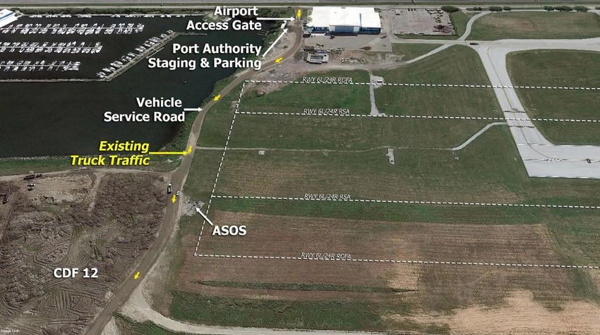
According to the 2017 ALP, the Runway 6L end is displaced 178’ allowing for 6,425’ for landing or
LDA. However, in 2020, Runway 6L operating lengths were reduced an additional 100’ (6,503’ for
TORA, TODA, and ASDA and 6,325’ for LDA). These declared distances were implemented for a
6L operation to mitigate a portion of existing VSR located within the ROFA and the road itself
being an obstruction to the departure surface (see Figure 1-6).
Figure 1-6 – Runway 6L Safety Areas
Source: CHA, 2021.
The Runway 24R threshold is currently displaced 600’ providing 6,003’ for landing aircraft. It is
constructed of asphalt with a grooved surface. The 24R departure end includes a 422-foot
Engineered Materials Arresting System (EMAS) bed. The runway’s load-bearing capacity is 93,000
pounds single-wheel; 113,000 pounds double-wheel; and 170,000 pounds double-tandem. This
runway has a Pavement Classification Number (PCN) of 84/F/C/X/T, which will be further
discussed in a subsequent section.
Situated between the primary runway and terminal facility, Runway 6R-24L is the Airport’s
secondary runway and is located 500 feet centerline to centerline to Runway 6L-24R. The runway
is 100 feet wide with a usable runway length of 5,199 feet, with a 275-foot displaced threshold
on the 6R end. It is constructed of asphalt and has a grooved surface. The runway’s load-bearing
capacity is 43,000 pounds single-wheel; 50,000 pounds double-wheel; and 82,000 pounds
double-tandem, and has a PCN of 63/F/C/X/T.
1.4.3 Taxiway System
An airport’s taxiway system connects the runways to aircraft parking aprons, storage hangars and
other facilities. At BKL, Taxiway ‘G’ serves as the parallel taxiway between the aprons and Runway
6R-24L. The remaining taxiways serve as connectors, with Taxiway ‘B’ as a high-speed runway
exit. Figure 1-7 and Table 1-5 provide the characteristics and specifications of each taxiway.
May 2021 DRAFT Inventory of Existing Facilities and Conditions 1-13AIRPORT LAYOUT PLAN (ALP) UPDATE NARRATIVE REPORT // Burke Lakefront Airport
Figure 1-7 – Existing Taxiways
Source: CHA, 2021.
Similarly, to ADG, taxiways are classified based on Taxiway Design Group (TDG). The TDG sets the
criteria for design minimums of taxiways and their safety areas. All the taxiways have a width of
75’, a Taxiway Object Free Area (TOFA) of 131’, and Taxiway Safety Area (TSA) of 79’. While it will
be further discussed in Chapter 3, BKL currently employs TDG-2 on all taxiways for TOFA and TSA;
however, a typical TDG-2 would only be 35’ wide.
Table 1-5 – Existing Taxiway Specifications
Taxiway Taxiway Object Taxiway
Width
Taxiway Safety Area Free Area Design Group
(feet)
(feet) (feet) (TDG)
A 75 79 131 TDG-2
B 75 79 131 TDG-2
C 75 79 131 TDG-2
D 75 79 131 TDG-2
E 75 79 131 TDG-2
F 75 79 131 TDG-2
G 75 79 131 TDG-2
H 75 79 131 TDG-2
Source: FAA Airport Diagram, AC 150/5300-13A, CHA 2021.
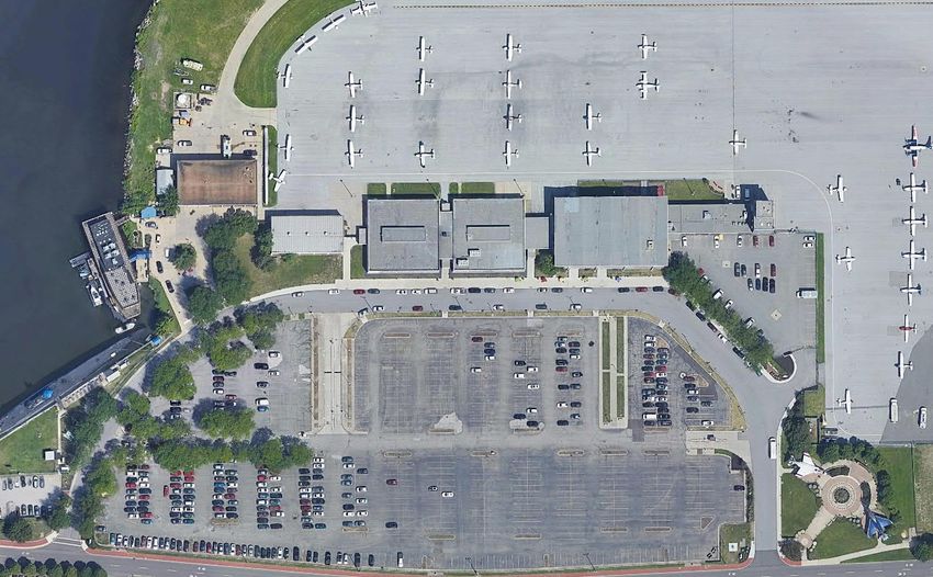
1.4.4 Aircraft Parking Aprons
Airport aprons, also referred to as ramps, provide space for short-term and long-term aircraft
parking and deicing operations, as well as the loading/unloading of passengers and goods. There
is an approximately 18,000 square foot (SF) apron on the north side of the main terminal and an
approximately 32,000 SF apron between the terminal and Signature Flight Support facility, who
serves as the FBO for BKL. These aprons are both for storage of itinerant aircraft, as well as
operations for Ultimate Air Shuttle. The FBO additionally maintains an approximately 8,000 SF
apron around their hangar, and an approximately 5,000 SF apron around their operations facility.
These aprons are shown in Figure 1-8.
May 2021 DRAFT Inventory of Existing Facilities and Conditions 1-14AIRPORT LAYOUT PLAN (ALP) UPDATE NARRATIVE REPORT // Burke Lakefront Airport
Figure 1-8 – Apron Areas
Signature (FBO) Aprons
Terminal Apron
FBO Transient
Apron
1.4.5 Airfield Markings
FAA AC150/5340-1M, Standards for Airport Markings, provides the standards for surface
markings used on airfield roadways and airfield pavements, such as runways, taxiways, and
aprons, assuming the surfaces are built in accordance to the standard dimensions and layouts in
AC 15/5300-13, Airport Design (this excludes privately owned apron areas). These standards
apply to all airports certificated under Title 14 CFR Part 139, which establishes certification
requirements for airports serving scheduled air carrier operations. Examples of airfield markings
are provided in Table 1-6 and Table 1-7.
Table 1-6 – Runway Markings
Type of
Purpose of Marking
Marking
Numbers and letters are determined from approach direction; labeled according to Compass
Designation
Rose
Centerline Identifies the center of the runway; Provides alignment guidance during takeoff and landings
Threshold Delineates the beginning of the runway that is available for landing
Serve as a visual aiming point for a landing aircraft, located approximately 1,000 feet from the
Aiming Point
landing threshold
Touchdown Identify the touchdown zone for landing operations and are coded to provide distance
Zone information in 500 feet increments
Runway
Define the edge of the usable, full-strength surface
Edge Marking
Source: CHA, 2021.
May 2021 DRAFT Inventory of Existing Facilities and Conditions 1-15AIRPORT LAYOUT PLAN (ALP) UPDATE NARRATIVE REPORT // Burke Lakefront Airport
Table 1-7 – Taxiway Markings
Type of Marking Purpose of Marking Visual Representation of Marking
Provides a visual cue to permit taxiing
Normal Centerline
along a designated path
Intended to warn the pilot that he/she is
approaching a runway holding position
marking and should prepare to stop
Enhanced Centerline
unless he/she has been cleared onto or
across the runway by ATC; Usually at
larger, commercial service airports
Continuous- Define the taxiway edge
from the shoulder or other abutting
paved surface not intended for use by
Edge Markings
aircraft; Dashed- Defines the taxiway
edge from the adjoining pavement
intended for use by aircraft
Identifies paved shoulders (areas
intended to prevent blast and water
Shoulder Markings
erosion); not intended for use by aircraft
(may not be full-strength pavement)
Indicate where an aircraft is supposed to
Runway Holding Position
stop when approaching a runway
Indicate where an aircraft is supposed to
Taxiway/Taxiway Intersection stop when approaching intersecting
taxiways
Source: CHA, 2021.
1.4.6 Airfield Signage
According to Title 14 CFR Part 139.311, Marking, Signs, and Lighting, each certificate holder, such
as BKL, must provide and maintain sign systems for air carrier operations on the airport that are
authorized by the Administrator and consist of at least the following:
Signs identifying taxiing routes on the movement area.
Holding position signs.
May 2021 DRAFT Inventory of Existing Facilities and Conditions 1-16AIRPORT LAYOUT PLAN (ALP) UPDATE NARRATIVE REPORT // Burke Lakefront Airport
Instrument Landing System (ILS) critical area signs.
The holding position signs, as well as the ILS critical area signs, must be internally illuminated.
FAA AC 150/5340-18G, Standards for Airport Sign Systems, contains all regulations pertaining to
airfield signage for Part 139 airports, while specifications are contained in AC 150/5345-44K,
Specifications for Runway and Taxiway Signs. A further description of typical airfield signage is
included in Table 1-8. See AC 150/5340-18G, Glossary of sign types, for additional sign type
descriptions.
Lighted signage on BKL’s airfield consists of all required signage for a Part 139 certificated airport
including airfield location signage, mandatory instruction signage, and runway hold position
signage. Additional signage may be required to accommodate future improvements or additions
to airfield pavements.
Table 1-8 – Airfield Signage
Type of Sign Purpose of Sign Visual Description of Sign
Denote taxiway/runway intersections, runway/runway
intersections, Instrument Landing System (ILS) critical areas,
Mandatory White Inscription/Red
Precision Obstacle Free Zone (POFZ) boundaries, runway
Instruction Sign Background
approach areas, CAT II/III operations area, military zones, and no
entry zones
Identify the taxiway or runway apron upon which the aircraft is Yellow Inscription/Black
Location Sign
located Background
Identify the boundary of the Runway Safety Area (RSA)/Object Black Inscription/Yellow
Boundary Sign
Free Zone (OFZ) or ILS critical are for a pilot exiting the runway Background
Black Inscription/Yellow
Indicate directions of other taxiways leading out of an
Directional Sign Background; Always
intersection
Contains an Arrow
Black Inscription/Yellow
Destination
Indicate the direction to a remote location Background; Always
Sign
Contains an Arrow
Runway
Provide distance remaining information to pilots during takeoff White Inscription/Black
Distance
and landing operations Background
Remaining Sign
Source: FAA AC 150/5340-18G.
1.4.7 Navigational Aids (NAVAIDs) and Instrument Procedures
Pilots utilize a variety of navigational aids (NAVAIDs) and instrument procedures, including
standard terminal arrival routes (STARs), instrument approach procedures (IAPs) and NAVAIDs,
approach lighting systems (ALS), airfield lighting, and rotating beacons. By providing point-to-
point guidance information or position data, NAVAIDs assist pilots to locate airports, land aircraft,
taxi aircraft, and depart safely and efficiently from airports during nearly all meteorological
conditions. Table 1-9 summarizes the Airport’s existing instrument approach procedures, by
runway, and the NAVAIDs required.
May 2021 DRAFT Inventory of Existing Facilities and Conditions 1-17AIRPORT LAYOUT PLAN (ALP) UPDATE NARRATIVE REPORT // Burke Lakefront Airport
Table 1-9 – Navigational Aids (NAVAIDs) and Approach Lighting
Runway Approach Minimum Ceiling Instrument
Runway
Markings Lighting (AGL)/ Visibility Approach Types
6L Precision PAPI, REIL VFR -
24R Precision PAPI, MALSF ¾-mile ILS (Category I), LOC, GPS
6R Basic - VFR -
24L Basic REIL VFR -
Source: FAA Airport Master Record (Form 5010), Accessed 2021.
Precision Approach Path Indicator (PAPI) Lights
A PAPI is a system of lights located near a runway end. It provides pilots with visual glide slope
guidance information during an approach to the runway. PAPIs typically have an effective visual
range of at least three miles during the day and up to 20 miles at night and inform pilots if they
are high, low or on the correct approach descent path for the threshold. Runway 6L-24R is
equipped with a PAPI system on both ends.
Standard Terminal Arrival Routes (STARs)
Standard Terminal Arrival Routes (STARs) are preplanned IFR air traffic control arrival procedures
published for pilot use. STARs serve as a critical form of communication between pilots and ATC
by providing a method and criteria for descent, routing, and communications when navigating to
the destination after leaving the en-route structure. The STAR and approach procedures virtually
connect to each other in such a way as to create a seamless transition.
Once a flight crew has accepted a clearance for a STAR, they have communicated with the
controller what route, and in some cases what altitude and airspeed, they will fly during the
arrival, depending on the type of clearance. BKL’s ATC has three STAR procedures: BRWNZ THREE,
ROKNN THREE, and TRYBE FOUR.
Types of Instrument Approach Procedures (IAPs) and Instrument Approach NAVAIDs
Based on current FAA classifications, there are four types of instrument approach categories:
Visual (V) – Approaches performed under visual flight rules only when meteorological
conditions include a cloud ceiling height of 1,000 feet or greater and visibility of 3 miles
or greater. Runway approaches for 6R, 6L, and 24R operate under visual conditions only.
Non-Precision Approach (NPA) – Instrument approach procedures providing only lateral
guidance with a ceiling minimum of 400 feet above the threshold. These can include VHF
Omnidirectional Range (VOR), non-directional beacon (NDB), area navigation (RNAV),
lateral navigation (LNAV), localizer performance (LP), and localizer (LOC) equipment. At
BKL, Runway 24R has an NPA procedure.
Approach Procedure with Vertical Guidance (APV) – Instrument approach procedures
providing vertical guidance minimums of 250 feet above the threshold and visibility
minimums as low as ¾ mile. These can include an ILS, LNAV/Visual Navigation Aids
(VNAV), Localizer Performance with Vertical Guidance (LPV) or Area Navigation (RNAV)
Required Navigation Performance (RNP). Runway 24R maintains this procedure.
May 2021 DRAFT Inventory of Existing Facilities and Conditions 1-18You can also read