BW/BWS
Weighing Indicator
←
→
Page content transcription
If your browser does not render page correctly, please read the page content below
BW/BWS Weighing Indicator
BW/BWS Series Indicator Technical Manual

                                           -1-
CONTENTS
1. SPECIFICATION..…………………………………………………………………. 2
2. INTRODUCTION…………………………………………………………………... 3
3. INSTALLATION……………………………………………………………………. 4
   Precautions …………………………………………………………………………4
   Parts………………………………………………………………………………… 4
   Installation………………………………………………………………………….. 5
4. KEYS DESCRIPTION……………………………………………………………... 6
   Key Board…………………………………………………………………………... 6
   Secondary functions of the keys………………………………………………….7
   Display……………………………………………………………………………….7
5. OPERATION……………………………………………………………………… 8
   5.1. Basic Operation…………………………………………………………... ...8
     1. Power On /Off………………..………………………………………………8
     2. Zero…………………………………………………………………………...8
     3. Tare…………………………………………………………………………...8
     4. Select Unit……………………………………………………………………8
   5.2. Check Weighing……………………………………………………………..9
        5.2.1. Set Limits…...……………………………………………..………….9
        5.2.2. Set Check Weighing………..……………………………………….9
   5.3. Accumulation…………………………………………………………………10
        5.3.1. Memory Recall……………...…………………….………………….10
        5.3.2. Memory Clear………………………………………………………...10
        5.3.3. Automatically Accumulation………………………………………...10
   5.4. Parts Counting...……………………………………………………………..11
   5.5. Animal Weighing……………………………………………………………..11
   5.6. Key Board Lock………………………………………………………………11
   5.7. Set Auto Power Off…………………………………………………………..12
   5.8. Set Back Light………………………………………………………………..13
6. PARAMETERS…………………………………………………………………….14
7. CALIBRATION……………………………………………………………………..16
8. RS-232 OUTPUT…………………………………………………………………17
   8.1. Specifications……………………….………………………………………17
   8.2. Connecter……………………………………………………………………17
        RS-232 Output………………………………………………………………17
        Check weighing Output…………………………………………………….17
   8.3. Continues output protocol………………………………………………….17
9. DRAWING…………………………………………………………………………19
   9.1. BW Drawing………………..………………………………………………19
   9.2. BW Parts List……………………………………………………………….20
   9.3. BWS Drawing………………………………………………………………21
   9.4. BWS Parts List……………………………………………………………..22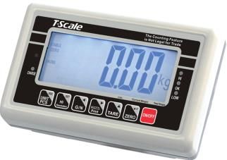
BW/BWS Series Indicator Technical Manual
PRECAUTIONS
WARNING
DISCONNECT ALL POWER TO THIS UNIT
BEFORE INSTALLING, CLEANING, OR
SERVICING. FAILURE TO DO SO COULD
RESULT IN BODILY HARM OR DAMAGE THE
UNIT.
CAUTION
Permit only qualified persons to service the instrument
Before connecting or disconnecting any components, remove the
power.
Failure to observe these precautions bodily harm or damage to or
destruction of the equipment.
The weighing indicator is a precision electronic instrument,
handle it carefully.
Do not install the scale in direct sunlight.
Verify the local voltage and receptacle type are correct for
the scale.
Only use original adaptor, other could cause damage to the
scale.
Pluggable equipment must be installed near an easily
accessible socket outlet.
Avoid unstable power sources. Do not use near large users
of electricity such as welding equipment or large motors.
Avoid sudden temperature changes, vibration, wind and
water.
Avoid heavy RF noise.
Keep the indicator clean
-1-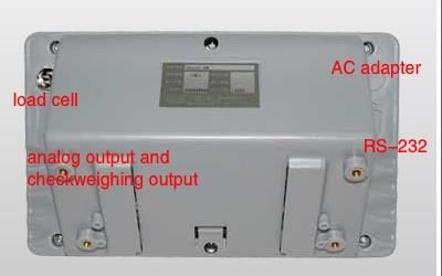
BW/BWS Series Indicator Technical Manual

                  1. SPECIFICATION

Model                      BW        BW-E         BWS       BWS-E
Display                 52mm LCD 1.2” LED 52mm LCD 1.2” LED
Housing                     ABS Plastic                 SST
Operating Temperature           -10°C - 40°C / 14°F - 104°F
Resolution                      1/6000 (OIML Approved)
Key Pad                                    7 Keys
Power                    AC Adaptor (12V/500mA)/ Battery (6V/4Ah)
Calibration                         Automatic External
Interface                        RS-232 Output Optional
Load cell drive Voltage               Max: 5V/150mA
Load Cells                           Up to 4 load cell
ADC                                     Sigma Delta
ADC Update                             ≤1/10 second
Stabilization Time                 One seconds typical

                                                                    -2-
BW/BWS Series Indicator Technical Manual
2. INTRODUCTION
The BW series weighing indicator that amplifies signals from a load cell,
converts it to digital data and displays it as a mass value.
It is suitable for general weighing or more specialized applications such as
check weighing, animal weighing and accumulation applications.
It can connect the indicator to a printer or a PC.
Large LCD with white LED back light displays
-3-BW/BWS Series Indicator Technical Manual
3. INSTALLATION
Unpacking
When you receive the scale, inspect it to make sure that it is not damaged and
that all are parts are included:
Remove the Indicator from the carton.
Remove the protective covering. Store the packaging and to use if you
need to transport the scale later.
Inspect the indicator for damage.
Make sure all components are included.
1. Indicator
2. Adaptor
3. Manual
4. Indicator holder (Optional)
5. Load cell Output connecter (Optional)
6. RS-232 Output Connecter (Optional)
Parts Description
-4-BW/BWS Series Indicator Technical Manual
Installation
Place the Indicator on a table or use indicator holder to connect with stand.
Connect the plat form load cell cable in to the indicator load cell connecter.
Load cell connecter is locating back side of the indicator.
Connect the adaptor pin in to the indicator adaptor jack.
Adaptor jack is locating, back side of the indicator.
Adaptor connects into your AC power socket.
Pluggable equipment must be installed near an easily accessible socket
outlet with a protective ground/ earth contact.
Turn on the On/Off key. If you want to turn off, press the key again.
Display will be show the scale capacity and will be starting self checking.
After self checking, display will be come to normal weighing mode.
Warm-up time of 15 minutes stabilizes the measured values after
switching on.
Calibrate with exact calibration weights, minimum 1/3 of the scale capacity
want to use for calibration. For calibration see details in parameter.
Then you can start your operation
-5-BW/BWS Series Indicator Technical Manual
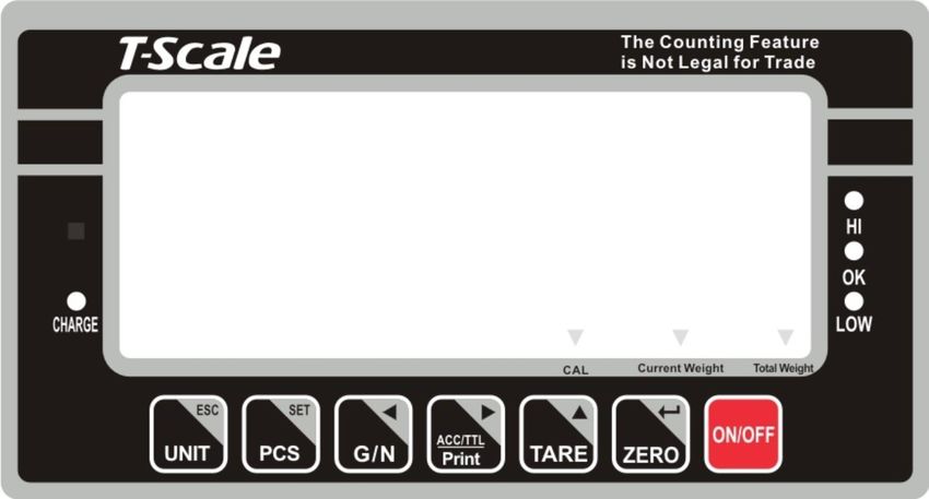
4. KEYS DESCRIPTION
Key Board
Keys Description
Power turn ON/OFF
Set the Zero Display
To perform a tare function, Subtracts weights.
Accumulator key, current values will store to the memory,
To send the data to printer or PC
Shift to Gross / Net Weight.
Counting
To change the unit
-6-BW/BWS Series Indicator Technical Manual
Secondary functions of the keys
Function Keys
To confirm the selected menu
To change the menu and active digit
To move the active digit to right
To move the active digit to left
To enter in to the menu
Escape from the menu to normal operation.
-7-BW/BWS Series Indicator Technical Manual
5. OPERATION
Initial Start-up
Warm-up time of 15 minutes stabilizes the measured values after switching on.
5.1. Basic Operation
1. Power On/Off:
Switch on the balance by pressing on/ off key.
The display is switched on and the test is started and if want to switched
off, press again the key.
2. Zero
Environmental conditions can lead to the balance exactly zero in spite of
the platform not taking any strain. However, you can set the display of
your balance to zero any time by pressing key and therefore ensure
that the weighing starts at zero.
3. Tare
The weight of any container can be tared by pressing button so that
with subsequent weighing the net weight of the object being weighed is
always displayed.
Load weight on the platform.
Press key. Zero is displayed, and tare is subtracted.
Remove weight on the platform. Tared weight is displayed. It can set only
one tare value. It will be shown with a minus value.
Press G/N to change between gross weight and net weight.
To clear the tare value, remove the load and press key. Zero is
displayed, tare weight is cleared.
4. Select Unit and Sampling operation
Press key, it can change unit and sampling operation.
-8-BW/BWS Series Indicator Technical Manual
5.2. Check Weighing
It can set an upper or lower limit when weighing with the limits range.
During the limit controls dividing the unit will indicate whether a value
upper or lower limits with an alarm sound .
5.2.1. Set Limits
Press and key together, display will be show set h.
Press key to select set h or set l
Press key to confirm, display will show 00000 and will blink the last
digit.
Enter the high limit value by using and keys to change the
active digits and press key to increment the value.
Press key to confirm, display will show set l
Enter the high limit value by using and keys to change the
active digits and press key to increment the value.
Press key to confirm.
To escape from the settings press key.
5.2.2. Set Check Weighing
Press and key together, display will be show set h.
Press key to select display beep.
Press key to confirm, display will be shown none or ok or ng
Check mode none : No beep sound in the limits. Function turned off.
Check mode ok : When the weight is between the limits. OK will shown
-9-BW/BWS Series Indicator Technical Manual
and beeper will be sounded.
Check mode ng : When the weight is out of the limits, the beeper will be
sounded and OK will shown.
Note: Check weighing available only when weight more than 20d
5.3. Accumulation
The scale can be set to accumulate manually by pressing key. For settings,
see the parameter p 1 Com » mode » pr 2
Before operation scale should be stable and return to zero, accumulation
available only when weight more than 20d
Accumulation Operation
Place the load on the platform.
Press key, when displayed STABLE indication.
Display will be show acc 1 then will be show the total saved value.
These displays will be shown only three seconds.
Remove the weight from the pan.
When display get zero and stable then place the second weight.
It can continue until the memory gets fully or 99 items.
5.3.1 Memory Recall
To recall the memory press key.
Display will be show acc X (X: Total number of accumulation) then will be show
the total saved value. These displays will be shown only three seconds.
5.3.2. Memory Clear
To clear the memory, press and keys together.
Display will be show Acc 0 , all accumulation memory cleared from the memory.
5.3.3. Automatically accumulation.
- 10 -BW/BWS Series Indicator Technical Manual
The scale can be set to accumulate automatically. For settings, see the
parameter p 1 Com » mode » auto
Automatic Accumulation Operation
Place the load on the platform.
When display gets STABLE indication, display will be show acc 1 then
will be show the total saved value. These displays will be shown only three
seconds.
Remove the weight from the pan.
When display get zero and stable then place the second weight.
It can continue until the memory gets fully or 99 items.
5.4. Parts Counting
To enter the parts counting, press key and select until display will be show
p 10
Press to change the parts quantity.
Options: p10 / p 20 / p 50 / p100 / p 200
Parts Counting Operation
Select the parts quantity as per the option
Place the load on the platform
Press key to confirm, display will be shown ---- then will show
the quantity
Then can add goods on the platform, display will update the parts quantity
automatically
Press key back to the weighing mode..
5.5. Animal Weighing
BW/BWS can use for vibrate loads weigh. This function can use for animal
weighing. For settings, see the parameter p 3 oth » anm
Bring the load on the platform, when the load few seconds get stable, the reading
will be locked for few seconds.
It can add or remove loads also update the weighing locked values.
- 11 -BW/BWS Series Indicator Technical Manual
To enter or exit animal weighing mode, press key until HOLD indicator will
be displayed or not..
When in animal weighing mode HOLD indicator will be displayed.
5.6. Keyboard Lock
It can set lock key board, for settings, see the parameter p 3 oth » lock
When the keys are not using with in 10 minutes, the keys will be lock
automatically.
After entering into the lock function, when we press the keys display will be show
k-lok. Then will come to normal display.
If want to unlock and want to use the keys press and hold , and
keys three seconds. Display will be show u lck Then will come to normal
display
5.7. Set auto power off
It can set auto power of the scale, when scale not in use, scale will turn off after
the setting time.
Hold key three seconds display will show setbl
Press key to change Set of and press key to confirm
Press key to change the options.
off To set auto off function turn off, for scale always
Set of on
Of 5 Set to turn off five minutes later
Of 15 Set to turn off fifteen minutes later
After select the auto off option press key to confirm and press
key to escape from the settings.
5.8. Set Back Light
- 12 -BW/BWS Series Indicator Technical Manual
It can set back light when scale in use.
Hold key three seconds display will show setbl
Press key to confirm
au To set auto option. When start to use back light
setbl will be on and when stop the operation back light
also will off.
on To set always on. After turn on the power, back
light also will be on.
off To set back light turn off. No back light in the
operations
After select the back light option press key to confirm and press
key to escape from the settings.
- 13 -BW/BWS Series Indicator Technical Manual
6. PARAMETERS
To set parameter, turn on the scale.
Press key during the self checking.
Display will be show pn
Press , and to enter, display will be show po chk
Menu Sub Menu Description
P 0 Set H Set high limits for check weighing
chk Set L Set low limits for check weighing
beep NONE No beep for check weighing
Ok Beep, when check weighing
between the limits
ng Beep, when check weighing out of
the limits
This option is used to set
accumulation and RS-232
P 1 Mode communication
com Options:
Cont : data send continues
St 1 : Send data one time,
when stable.
St c : Send data continuously,
when stable
P r1 : Send data one time,
when press print
Key (in printer mode)
Pr 2 : Send data to print and
accumulation,
When press .key
Auto : Auto accumulate and
auto print mode.
When weight stable and
return to zero.
Ask : Ask mode,
Command R: read data
Command T: Tare
Command Z: Zero
Wireles: Wireless mode
(communication
through wireless)
- 14 -BW/BWS Series Indicator Technical Manual
Baud To set the baud rate.
Options:
600 / 1200 / 2400 / 4800
/ 9600
Pr To set the parity
Options:
7 e1 / 7 o1 / 8 n1
Ptype To set printer model
Options:
Tpu p : set the Tscale printer tpup
Lp50 : Set the Tscale printer LP-
50
To select single range operation
Count To check internal counts
Si g r Deci To set decimal points
Div To set increment
Cap Set Capacity
Cal Calibration
gra Gravity
To select dual range - mode 1
Note: Once active second interval (div 2), Then
second interval will work until display return to zero
Count To check internal counts
Dual 1
P 2 Deci To set decimal points
mod Div Di v 1 To
select
first
division
Di v 2 To
select
second
division
Cap Cap 1 To
select
first
capacity
Cap 2 To
select
second
capacity
Cal Calibration
- 15 -BW/BWS Series Indicator Technical Manual
gra Gravity
To select dual interval - mode 2
Note: First interval will active in CAP 1
Second interval will active in CAP 2
Count To check internal counts
Dual 2 Deci To set decimal points
Div Di v 1 To
select
first
division
Di v 2 To
select
second
division
Cap Cap 1 To
select
first
capacity
Cap 2 To
select
second
capacity
Cal Calibration
gra Gravity
P3 oth Lock To set keypad lock
Options: on / off
anm To set animal mode.Options: on / off
P4 ST ST To set Multiple tare function
Options: on / off
P5 clr Clr cal Clear calibration for the record
Clr opt Clear operation for the record
7. CALIBRATION
To set calibration, turn on the scale.
Press key during the self checking.
Display will be show pn
Press , and to enter, display will be show po chk
Press until display will be show p 2 mod.(These is a switch on the
main board you need to press it then can into the parameter)
- 16 -BW/BWS Series Indicator Technical Manual
Press key to confirm and press to select sigr /dual 1
/dual 2
Press key to confirm and press to select cal
Press key to confirm
Calibration Cal
Press key to enter calibration, display will show kg or lb. press
key to select the calibration unit kilograms or pounds, press
key ,display will be show unld
Remove all the weight from the platform.
When indicator get stable, press key to confirm.
Display will be show the last calibration weight. If want to change the
calibration weight value, press and keys to change the active
digits and press key to increment the value.
When the calibration value is correct, press key to confirm.
Display will be show load
Place the calibration weight on the platform.
When indicator get stable, press key to confirm.
Display will com to normal weighing mode
8. RS-232 OUTPUT
8.1. Specifications:
RS-232 output of weighing data
Code : ASCII
Data bits : 8 data bits
Parity :No Parity
Baud rate : 600bps to 9600bps selectable
- 17 -BW/BWS Series Indicator Technical Manual
8.2. RS-232 (9pin D type connector)
Pin 2 RXD Input Receiving data
Pin 3 TXD Output Transmission data
Pin 5 GND ― Signal ground
9pin D Connecter:
Indicator Computer
Pin 2: Pin 3
Pin 3: Pin 2
Pin 5: Pin 5
Check Weighing Output
Pin 1 : VB
Pin 4: Vcc 5v (Output)
Pin 5: Com (Ground)
Pin 6: Ok (Output)
Pin 7: Low (Output)
Pin 8: Hi (Output)
Pin 9: Beep (Output)
8. 3. Continuously output protocol
Weighing mode
, -/ k g CR LF
-HEADER1-- - HEADER2- --- WEIGHT DATA -- -WEIGHT UNIT- TERMINATOR
Counting mode
P C S : p c s CR LF
- QTY - -QTY UNIT-
HEADER1: ST=STABLE, US=UNSTABLE
HEADER2: NT=NET, GS=GROSS
Con2:
Head Head Head Head Weig Weig Weig Weig Weig Weig Termin Termin
Tare1 Tare2 Tare3 Tare4 Tare5 Tare6
er0 er1 er2 er3 ht1 ht2 ht3 ht4 ht5 ht6 ator1 ator2
Header0=02H
Header1 follow decimal point
- 18 -BW/BWS Series Indicator Technical Manual
Decimal point=0, header1=22H
Decimal point=1, header1=23H
Decimal point=2, header1=24H
Decimal point=3, header1=25H
Decimal point=4, header1=26H
Header2 follow weigh status, default value=20H
If in net mode (tare value not 0), header2=header2|01H
If gross weight “-“, header2=header2|02H
If overload or gross weight “-“, header2=header2|04H
If unstable, header2=header2|08H
If weighing unit=kg, header2=header2|10H
Header3 follow weighing unit
If weighing unit=g, header3=21H
If weighing unit=oz, header3=23H
Weight1~weight6: weighing data
Tare1~tare6: tare value
Terminator1: 0DH
Terminator2: 0AH
Con3:
Header Header Weight Weight Weight Weight Weight Weight Weight Termin Termin
Unit1 Unit2 Status
0 1 1 2 3 4 5 6 7 ator1 ator2
Header0=01H
Header1 follow weight “+” or “-“
When weight “+”, header1=”+”, when weight “-“, header=”-“
Weight1~weight7: weight data (include decimal point)
Unit1~unit2: weight unit
Status: when stable, status=0, when unstable, status=1
Terminator1: 0DH
Terminator2: 0AH
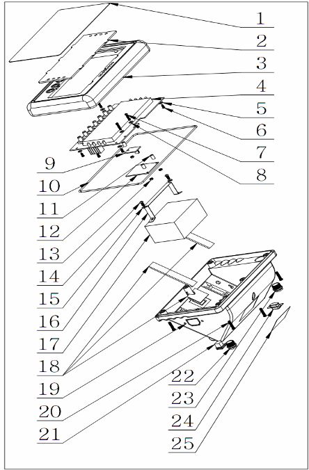
9. DRAWING
9.1. BW Drawing
- 19 -BW/BWS Series Indicator Technical Manual
9.2. BW Parts List
- 20 -BW/BWS Series Indicator Technical Manual
No Parts Name Qty Spec
1 Key Panel 1
2 Display Protection Plate 1
3 Front Cover 1
4 Main PCBA 1
5 Insulation Washer 6 8x3.1x1.5t
6 Self Thread Screw 6 3x10
7 Screw 3 M3x16 (Optional)
8 Insulation Washer 3 8x3.1x1.5t (optional)
9 RS-232 PCBA 1 (0ptional)
10 Seal Ring 1
11 Screw Column 3 5.8x3.8x10H (Optional)
12 Analog Output PCBA 1
13 Nut 3 M3, Hexagon
14 Self Thread Star (+) Screw 2 4x10
15 Washer 2 9x4.4x0.8t
16 Battery bar 1
17 Battery 1 6V/4Ah
18 Spacer 2 (Optional)
19 Back Cover 1 ABS
20 Self Thread Star (+) Screw 6 4x116
21 AC Adaptor Jack 1
22 Air Connecter 1 5Pin For load cell
23 Air Connecter 1 9Pin for Out Put (Optional)
24 D Connecter 1 9 Pin ( Optional0
25 Name plate 1
9.3. BWS Drawing
- 21 -BW/BWS Series Indicator Technical Manual
9.4. BWS Parts List
- 22 -BW/BWS Series Indicator Technical Manual
No Parts Qty Spec
1 Key Panel 1
2 Front Cover 1
3 Display Protection Plate 1
4 Nut 6 M3*6
5 Main PCBA 1
6 Washer 6 8x3.1x1.5
7 Star (+) Self Thread screw 6 M3x8
8 Water Proof Rubber Bar 1
9 Star (+) Screw 2 M4x10
10 Washer 2 M4
11 Battery Clamp 1
12 Washer 6 M4
13 Star (+) Big head Screw 6 M4x12
14 Bracket 1
15 Bracket Screw 2
16 Water Proof Adaptor jack 1
17 Interface Module 1
18 Air connecter 1 5Pin
19 Plug 1
20 Rubber Spacer 3
21 Air Connecter 1 7Pin
22 Back Cover 1
23 Air Connecter Water Proof Nut 1
24 Battery 1 6V/4Ah
25 Nut 1 M3x6
26 Main Serial board 1
27 Spacer 1
28 Star (+) Screw 1 3Mx20
29 Micro Switch Cap 7
- 23 -You can also read