TRANSFORMER CONTROL (AC-56a) - celduc relais solutions
←
→
Page content transcription
If your browser does not render page correctly, please read the page content below
Solid State Relays (SSR)

                       TRANSFORMER CONTROL (AC-56a)
                          celduc relais solutions  ®

               Tips and tricks to make good control of transformer primary
                                          ®
                              using celduc relais solutions

                                           TECHNICAL INFORMATION

     Switching ON the primary of an AC transformer can often generate high inrush currents.

     Frequent switching of the primary without adapted solution can lead to damages in the transformer
     primary circuit:
      -    The inrush current can cause the tripping of the circuit protection and the user may have to increase
           its current rating to allow a correct operation, leading to safety hazards with a bad coordination of the
           short circuit protection.
      -    The inrush current can damage the contacts of the mechanical contactors (arcing, welding because of
           the bounces at closing).
      -   The inrush current can also damage the primary winding of the transformer especially if the switching
          frequency is important
      -   The inrush current can make mechanical stress in the wires and connections because of the magneto-
          mechanical effect
     Using celduc® relais SSR instead of contactor can improve considerably the switching operation
     provided the user choose the right SSR switching mode. celduc® relais can help for the choice
     and this document gives information to understand our advices.

Application Note / Transformer Control / 03-2018
                                                       1/14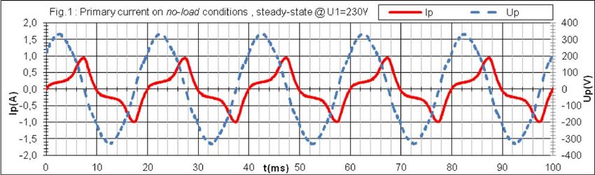
DIFFERENT CASE ANALYSIS
1) Non-saturable induction coils
This is typically air coils or transformers with an air gap.
The figures below show that the current value depends on the instant of switching. Whereas the zero
voltage cross switching creates an inrush current of the double from the nominal, the peak voltage
switching removes any problem of inrush current.
Fig. 1: zero cross starting current surge = 2Imax Fig. 2: peak starting, no current surge
2) Saturable induction coils
These are coils around a ferromagnetic metal (e.g. iron) without air gap like standard transformers.
Saturation occurs when the metal core cannot store induction anymore: the coil then tends to become an air
coil again.
Reminders:
t
1
N 0
Conversion from voltage to magnetic flux (in Weber, Wb): u.dt with u = voltage applied to the
coil and N = number of turns in the winding
Value of the induction (in Tesla, T): B with A=cross section of the iron core (in m²)
A
And also:B .H with µ, permeability (=µ0.µi) depends on the core material with µ0=4∏.10-7
N .I
Value of the magnetic field (in Ampere Turns, AT): H with N = number of turns in the winding, I
L
= current, L is the length of the magnetic circuit.
t
1
N 0
With B and u.dt , B is linked to the voltage u (the quantity applied for a given duration).
A
N .I B
With H and H , H is proportional to the current and depends on the voltage as well as the material
L µ
of the core.
Application Note / Transformer Control / 03-2018
2/14
Fig. 3: Magnetic hysteresis cycle

  Description of the phenomena:

  In ac steady state supply, the magnetic field H (and therefore the current in the coil) varies according to the
  induction B and as described with the hysteresis cycle shown fig. 3.
  At zero current (typical stop of ac SSR), a residual induction remains (like a magnet) in the magnetic circuit
  (+Br -Br).
  Without any connection to the mains, the remaining induction in the transformer can last for years like a
  permanent magnet.
  If the induction (linked to the voltage applied) comes in addition to the remanent induction Br (B>Bsat with
  Bsat depending on the core material), the magnetic circuit goes to saturation (the magnetic circuit cannot
  store anymore magnetic energy) and the current (proportional to H) increases dangerously. The current is
  then only limited by the resistance of the coil windings and that of the line (and sometimes the short circuit
  protection devices).

Application Note / Transformer Control / 03-2018
                                                              3/14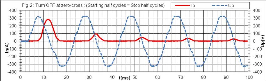
SWITCHING WITH STANDARD SOLID-STATE RELAYS

    a) Zero cross switching:           (e.g. control by zero cross SSR)

    Two cases can occur:

    Case Nr1: the starting is performed on the same half cycle polarity vs the previous current stop

                                                                                  2-SSR turns ON at zero voltage
                                                                                  crossing, same polarity of current
                                                                                  stop

   1-SSR turns OFF at zero
   current crossing

                                               Fig. 4: zero cross switching,
                                            stop and start with same polarities

Application Note / Transformer Control / 03-2018
                                                             4/14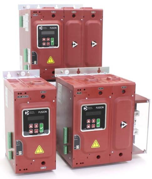
In most of cases, the Bsat saturation induction is exceeded. The amplitude of the current (proportional to
H), becomes very high.
In this sequence of switching, zero-cross control produces the most surges : this is the worst
case for a transformer and must be avoided
Case Nr2: In order to decrease this current surge, it is preferable to have full cycles in time (avoid adding
induction to the remaining induction). Therefore, zero-cross turn-on takes place on the half cycle opposite
that of the previous current stop.
SSR turns ON at zero voltage
crossing, opposite polarity of
current stop
SSR turns OFF at
zero current crossing
Fig. 5: zero cross switching, opposite polarities
This case is the ideal but requires working with the memory of the previous stop as otherwise the
case Nr1, the worst case, can occur especially if the main disappears (disconnection, missing cycles).
With a use of a zero cross solid state relay, the cycle polarities at turn OFF and at turn ON
must therefore be known to send the control. This is not standard zero cross relays.
It results that zero cross starting must be avoided on this type of load.
Application Note / Transformer Control / 03-2018
5/14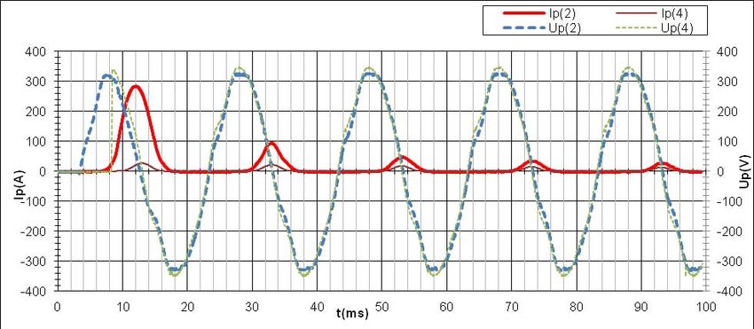
b) Random switching:             (e.g. control by a random SSR)

    The switching occurs at any point of the sine wave and the probability of zero cross switching is lower. With
    an external synchronization circuit, it is possible to fix the switching point to the best moment: peak of the
    voltage sinewave.
    This type of relay is anyway preferable to a zero cross relays but, as zero cross can occur, the relay inrush
    current rating must be chosen correctly.

                 With standard SSRs, it is preferable to use random relays, but in all cases,
                                the rating of the SSR should be oversized.

    The choice of the relay current rating must therefore be checked with the repetitive curve of Itsm = f(t).

                                                   Fig. 6: 125 Solid-state relay ITSM curve

    Extreme example with a relay of 125 A: With a surge of 10ms, the relay can withstand approximately
    1100A about.
    As the transformer inrush current can be as high as 100 times its nominal, the relay above can drive a
    transformer with a nominal current of around 11Arms taking 100In at starting, the max transformer
    current with this relay would be 11A i.e. 7.5kVA at 400VAC. As the line and the protections can also limit
    the current, a transformer of 10kVA can roughly be controlled with a 125A relay.

    Note 1: With small transformers, the winding resistance reduces significantly inrush current.

    Note 2: When the current inrush occurs, high current pulses are repeated every 20ms
    @50Hz with a small decrease in time: For this reason, the initial saturation current should
    be avoided.

Application Note / Transformer Control / 03-2018
                                                                6/14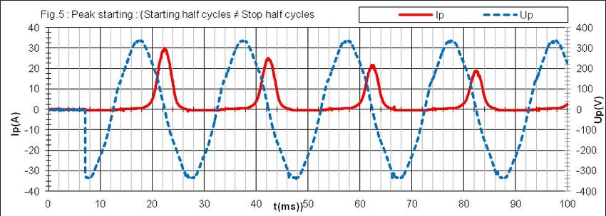
PEAK SWITCHING SOLID-STATE RELAY

    This consists in switching ON the SSR at the peak of the voltage sinewave.

    Two cases can occur:

    Case Nr1: The starting takes place at the peak but on the same half cycle as that of the previous stop.

                                                                                  SSR turns ON at the peak
                                                                                  voltage, same polarity of
                                                                                  current stop

        SSR turns OFF at
        zero current crossing

                                    Fig. 7: Peak switching, same polarities

    This type of control is still not the optimum as at start more induction is added to the remaining Br and
    could lead to an inrush current, but anyway much less than zero cross switching

    This type of control is proposed by the SOP69070

    100-510VAC
    32A-AC56a (with heatsink)
    125A-AC51 (with heatsink)
    Control: 5-30VDC

Application Note / Transformer Control / 03-2018
                                                             7/14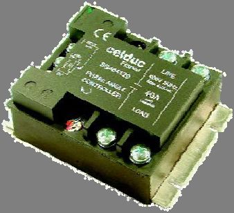
Case Nr2 : The starting takes place at the peak but on the opposite half cycle of that of the stop.
SSR turns ON at the peak
voltage, opposite polarity of
current stop
SSR turns OFF at zero
current crossing
Fig. 8: Peak switching, opposite polarities .
Note: If a transformer is very near Bsat at In, a small current surge may take place on the second half
cycle.
Conclusion: peak switching with or without full cycle
sequence is a good transformer inrush current solution.
SOP69070
100-510VAC
32A-AC56a (With heatsink)
125A-AC51 (With heatsink)
Control: 5-30VDC
Application Note / Transformer Control / 03-2018
8/14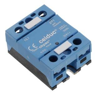
CASE STUDY: COMPARISON OF SWITCHING TECHNOLOGIES

    Transformer used for this case study: 3kVA 230V-13A /12V- 250A
    Primary current on no-load conditions: 0.5Arms

  Diagram                       ❶                    ❷                   ❸              ❹                ❺
                                                   Turn ON at          Turn ON at
  Case                     Steady-state                                             Peak starting    Peak starting
                                                   zero-cross          zero-cross
  celduc’s range                                      SO8                 SO8            SOP             SOP
                                                                   Starting half                    Starting half
                                              Starting half                         Starting half
                                                                   cycles ≠ Stop                    cycles ≠ Stop
  Conditions                                  cycles = Stop                         cycles = Stop
                                                                   half cycles                      half cycles
                                              half cycles                           half cycles
                                                                   (opposite)                       (opposite)
  Peak current                    1A                 280A                 5A            ~30A             ~30A
  (no-load condition)

       ❶

       ❷

Application Note / Transformer Control / 03-2018
                                                                9/14
❸
❹
❺
Application Note / Transformer Control / 03-2018
10/14❻
Comparison
of switching
between
zero-cross
SO8
(❸ )
and peak
SOP
(❹ )
Hysteresis cycle
measured for this
transformer
Application Note / Transformer Control / 03-2018
11/14OTHER SOLUTION: SOFTSTARTERS
The goal is to apply progressively the voltage to the primary of the transformer. This is one solution
for application that stays ON for a long time.
Fig. 9: Soft-start
For single phase transformers, this softstart function can
be built based on an analog proportional controller (e.g. SG4 series)
For 3 phase transformers, the softstart function can be done by SMCV or
SMCW series provided the secondary of the transformer is connected to a
minimum load (See the special application note SMCW on transformers). A
bypass contactor can be used to reduce the control system size.
Application Note / Transformer Control / 03-2018
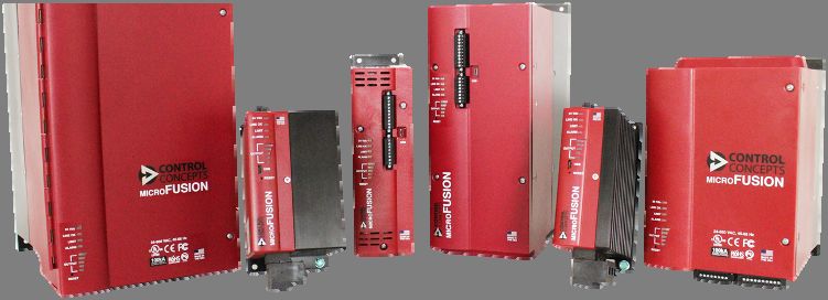
12/14OTHER SOLUTION: ZERO-CROSS TRANSFORMER CONTROL (ZCT)
For high power transformers (e.g. used for metal treatment), celduc® relais now offers a complete range
of Thyristor Power Controllers with 400A AC56b for the MicroFUSION range and up to 1200A AC56b for
the FUSION range.
Fig. 10: MicroFUSION series, Fig. 11: FUSION series,
1 phase, 2 phases or 3 phases up to 400Amps 1 phase, 2 phases or 3 phases up to 1200Amps
Fig. 1: ZCT operation
ZCT = Zero-Cross Transformer Control:
The power controller is meant to control the power at the primary of a transformer according the system
settings. The secondary voltage and current of the transformer varies accordingly.
To remove the risk of saturation of the transformer magnetic circuit and the inrush current, one solution
consists in using a phase angle controller with a current limit function. Unfortunately, this control mode
deteriorates the power factor of the installation.
MicroFUSION and FUSION series enclose a ZCT control mode which is a kind of zero cross burst firing
mode with all the benefits in terms of power factor. ZCT mode consists in keeping as much as possible
sine wave signals during cycle pulse trains, and applies a soft-start (phase angle control), limited in
current, only at the beginning of each ON periods.
Application Note / Transformer Control / 03-2018
13/14Advantages for transformer control:
- Limitation of the primary inrush current
- Better power factor than a permanent phase angle control
As the period of the pulse trains of cycles for the proportional control is quite slow (10 seconds OFF time
minimum), this mode is adapted to very slow reacting loads (big inertia) like big ovens. The benefit in
terms of power factor will be even more appreciated.
CONCLUSION
Applying electric power to the primary of a transformer can lead to more or less big troubles, especially if
this operation is intended to be very frequent.
Replacing a contactor with a standard solid-state relay requires to use at least a random switching version
and to use it at around 10% of its nominal current rating.
celduc® relais has launched a new solid-state relay SOP69070 featuring a peak control mode to drive up to
32A transformers. The SOP69070 is a very efficient control solution for small to medium transformers.
Including and far above 32A transformers (up to 1200A), celduc® relais proposes MicroFUSION and
FUSION Thyristor Power Controllers featuring, in addition to phase angle mode, ZCT control mode.
This ZCT mode removes the problem of inrush current and improves the power factor of the installation
compared to standard solutions.
Application Note / Transformer Control / 03-2018
14/14You can also read