Computational Storage For Big Data Analytics - ADMS 2019
←
→
Page content transcription
If your browser does not render page correctly, please read the page content below
Computational Storage For Big Data Analytics

                   Balavinayagam                                 Keith Chapman                              Mehdi Nik
                    Samynathan                                     Bigstream Inc.                          Bigstream Inc.
                      Bigstream Inc.                         keith@bigstream.co                      mehdi@bigstream.co
                bala@bigstream.co
                Behnam Robatmili                              Shahrzad Mirkhani                        Maysam Lavasani
                      Bigstream Inc.                               Bigstream Inc.                          Bigstream Inc.
             behnam@bigstream.co                         shahrzad@bigstream.co                     maysam@bigstream.co

ABSTRACT                                                                         high-level analytics languages used by data scientists and en-
This paper discusses the advantages and benefits of com-                         gineers. Data scientists and engineers are not able to easily
putation near storage or computational storage in the con-                       program and use these accelerators as they need to program
text of Big Data analytics. SmartSSD computational stor-                         using hardware description languages or low-level program-
age platform from Samsung provides an opportunity for fast                       ming languages such as CUDA/OpenCL. Even if the ven-
data transfers from storage to FPGAs, which can facilitate                       dors provide high level software libraries and APIs, the cost
acceleration of big data processing. In this paper, we dis-                      of changing analytics code is significant. Also, library calls
cuss our full stack acceleration approach, with zero appli-                      cannot take advantage of the run-time information associ-
cation code change, for modern open source Big Data envi-                        ated with the dynamic nature of the workloads as well as
ronments on accelerators like FPGAs and GPUs, with focus                         the dynamic nature of underlying resources. At Bigstream,
on Apache Spark as our Big Data environment and FPGAs                            we develop hardware-software solutions for enterprise and
as acceleration devices. We discuss changes that were made                       cloud-based data centers to fill this gap. Our software plat-
to our traditional software and hardware stack in order to                       form enables accelerated computing for Big Data analytics
incorporate computational storage platforms. The paper de-                       without requiring any code change. This is especially impor-
scribes cross-stack optimizations necessary to achieve high                      tant for cleansing, managing, and analyzing huge volumes
throughput and low latency for SQL query processing for                          of data that is required for AI/ML solutions. Today’s clus-
SmartSSDs. Finally, we showcase our results on TPC-DS                            ters are typically managed using distributed software frame-
benchmarks, which are state-of-the-art SQL benchmarks de-                        works on x86-based hardware servers, which include both
signed for Big Data analytic platforms. The results show up                      open source (e.g., Spark, Hive, etc.) [22] as well as closed
to 6x end to end query run-time speedup for scan-heavy                           source (e.g., Redshift, Microsoft SQL Server, Snowflake).
TPC-DS queries, compared to query run-time for the same                          In this work we focus on SmartSSD, which is a compu-
queries executed by vanilla Spark. The average speedup                           tational storage platform introduced by Samsung [5] as a
across all TPC-DS queries is 4x.                                                 hardware accelerator near storage. We utilize our technol-
                                                                                 ogy on SmartSSDs to process parts of analytic workloads in
                                                                                 the in-storage peered device (in this case, FPGA) and show
1.    INTRODUCTION                                                               significant performance and throughput improvements.
  As Moore’s law is slowing down, traditional CPU and                               The rest of the paper is organized as follows: the next
transistor scaling no longer translates to performance scal-                     section discusses prior work and background. Section 3 dis-
ing for data centers and cloud systems. As a solution to                         cusses SmartSSD components and operational mechanisms.
this problem, the industry has come up with a number of                          Section 4 describes layers of our software stack and how it
hardware accelerators to speedup processing in different do-                     enables acceleration without any user code change for an-
mains such as machine learning, data analytics and graph                         alytic applications. Sections 5 and 6 discuss the hardware
processing. A clear indicator of this trend is the fact that                     architecture we used and our hardware/software interfaces
accelerators such as FPGAs, GPUs and TPUs are now avail-                         respectively. Section 7 and Section 8 present our design and
able in cloud and data centers [7].                                              results on row-based data format for TPC-DS [6] bench-
  Unfortunately, there is a semantic gap that exists between                     marks, respectively.
the low-level programming model of the accelerators and the
                                                                                 2.   RELATED WORK
                                                                                   The concept of moving processing capability near storage
                                                                                 has been explored before in the form of intelligent disks [16]
This article is published under a Creative Commons Attribution License           and active disk [18]. However implementation of such sys-
(http://creativecommons.org/licenses/by/3.0/), which permits distribution        tems was not practical due to power and cost issues. Com-
and reproduction in any medium as well allowing derivative works, pro-           mercially this concept was first explored by adding FPGA
vided that you attribute the original work to the author(s) and ADMS 2019.       near disk in IBM’s Netezza product [13]. With regard to
10th International Workshop on Accelerating Analytics and Data Manage-
ment Systems (ADMS’19), August 26, 2019, Los Angeles, California, CA,            SSDs, computation near storage is an emerging technol-
USA.                                                                             ogy that can potentially become essential in modern data-

                                                                             1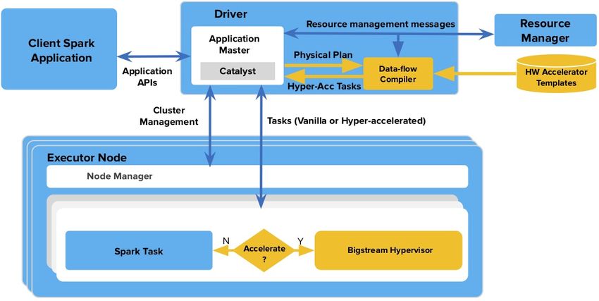
Figure 1: SmartSSD System Architecture1
                          1 Image   obtained with permission from https://youtu.be/OHWzWv4gCTs?t=639

center infrastructures so much so that the Storage Network-             work [17, 16, 10, 11]. The primary advantage is reducing
ing Industry Association (SNIA) has created a Computa-                  the computational complexity and volume of data reach-
tional Storage Technical Work Group to focus on standard-               ing CPU’s host memory and scaling processing capability
izing this technology [1]. The idea of query processing on              to maximize storage bandwidth.
SmartSSD has been researched [11] where queries were run                   The components of the SmartSSD platform are shown in
on Microsoft SQL Server on SmartSSD which had an embed-                 Figure 1. The SmartSSD platform contains a Xilinx FPGA
ded ARM processor. Studies like [15] and [21] also discuss              and NAND Flash Arrays with 1TB capacity on the same
using the same SmartSSD in the context of applications such             board which has the form factor of a PCIe add-in card.
as log analysis and document search while our work is fo-               The FPGA used in SmartSSD is a Zynq SoC and has ARM
cused on SQL Big Data analytics. The newer generation of                cores. The PCIe in this card is Gen3x4-lane with a theoret-
SmartSSDs has a FPGA instead of an embedded processor.                  ical maximum throughput of 4 GB/s. The board contains
This could lead to better acceleration as custom designs can            8 GB DRAM, which acts as an intermediate buffer when
perform better than general purpose processors. Our work                data is transferred from SSD to FPGA and from FPGA
utilizes the FPGA in SmartSSD without application code                  to host. There is a three-way PCIe switch present in the
change to provide speedup. Additionally, our framework                  FPGA, which can transfer data from/to SSD and FPGA and
is targeted towards Big Data environments, where clusters               from/to SSD to host memory and from/to FPGA to host
can extend to hundreds of nodes and data size can range                 memory. SmartSSD supports two modes of data transfer:
from petabytes to terabytes. Another distinguishing archi-              normal mode and Peer-to-Peer (P2P) mode. When operat-
tectural feature between previous generation SmartSSD and               ing in the normal mode, read/write is issued by the host and
the one used in this work is that they were based on SATA               data is transferred between SSD and host memory through
or SAS attached SSD while we work with a PCIe attached                  PCIe. A normal read corresponds to how data is read by ap-
card which provides higher SSD throughput. Our software                 plications of a normal SSD. It is important to note that un-
interfaces use OpenCL API to access SmartSSD from host                  der normal reads too, data is transferred through the PCIe
application when compared to the OPEN, GET and CLOSE                    switch in the FPGA onto the PCIe Bus. The second mode of
requests [11] in a session based protocol and this leads to a           operation is the Peer-to-peer (P2P) mode, in which data is
better event model for our applications as explained in 7.              transferred from SSD to FPGA DRAM for processing by the
There has also been other work that explored part of query              local peered devices. For the P2P mode, there is a reserved
execution near SSD [14], where the query planner was mod-               memory in the FPGA DRAM which we call Global Acces-
ified to offload filter functions to ARM processor in SSD               sible Memory (GAM) and is accessible by SSD, FPGA, and
controller. This would work best in the cases where data is             host. This GAM is exposed to the host PCIe address space.
plain-encoded since the ARM processor would find parsing a              From the software perspective, all access to accelerators and
compressed file computationally intensive. Our implemen-                computing on P2P data in the SmartSSD goes through the
tation does scan and filtering for compressed data as well              Xilinx OpenCL framework [12]. An application that would
since the FPGA can do decompression, decoding, parsing,                 like to use the P2P mode from host software needs to allo-
and then apply filter functions.                                        cate memory in the GAM using OpenCL libraries and ex-
                                                                        tensions provided by Xilinx (clCreateBuffer with P2P flag
3.   SMARTSSD ARCHITECTURE                                              in this case). The allocated memory can then be used by
                                                                        the SSD for direct read/write access into FPGA GAM. This
   With the ever-growing amount of data that needs to be                constitutes P2P mode of operation for the SmartSSD.
processed by data centers, it is critical that servers be able to
consume data effectively from storage devices. In this paper,
we define computational storage as the ability to do compu-
tation or data processing at the storage device level or near
                                                                        4.   A COMPUTATIONAL STACK FOR BIG
storage, before data is moved to host memory. This paper                     DATA ACCELERATION
exclusively discusses computational storage with respect to               This section demonstrates layers of our software stack
the SmartSSD platform from Samsung [5]. The advantages                  which facilitate the process of using accelerators in Big Data
of having computational storage has been discussed in prior             applications seamlessly. Our technology stack consists of

                                                                    2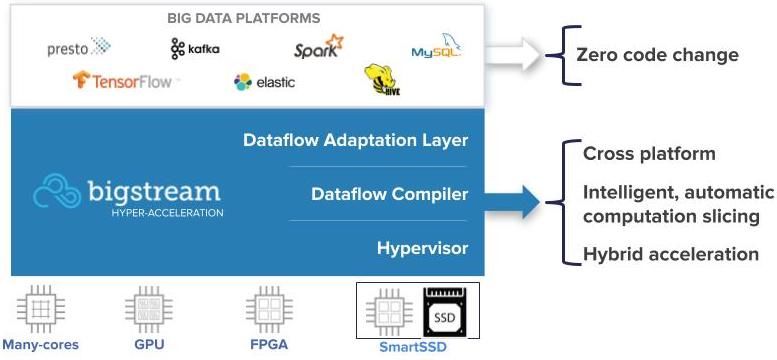
Figure 2: Hyper-acceleration technology
three important layers as illustrated in Figure 2: data-flow
adaptation layer, data-flow compiler, and hypervisor. The
following section describes these layers in more detail.
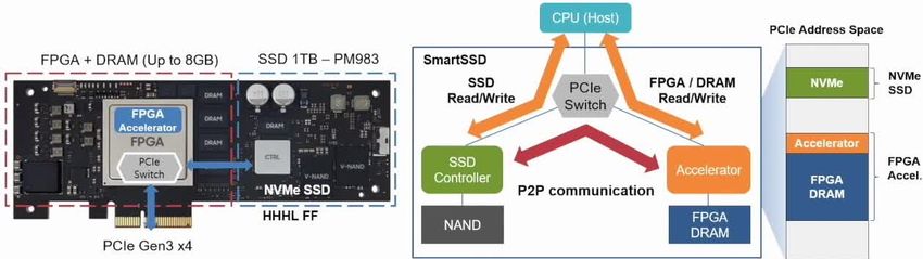
Figure 3: Spark Execution Illustrated With 3 Tasks
1. The data-flow adaptation layer converts internal and 2 Stages
data-flow format of Big Data frameworks like Apache
Spark, Hive, Presto, or Tensorflow into Bigstream’s
canonical data-flow format. In this paper, we focus different types of accelerator devices across the three layers
on Apache Spark [22] which is one of several Big Data described here.
application frameworks popular for its higher perfor-
mance due to in-memory processing. Bigstream canon- 4.1 Spark Execution Overview
ical data-flow format includes several computation- and The scope of this article is limited to Spark SQL. In
communication-related operators that cover analytics Apache Spark, a user application is executed by a driver
and machine learning operations. The implementation program and one or more executors [22]. The driver program
of these operators is not tied to any specific platform. takes user code and dispatches it to executors across mul-
(The canonical data-flow format, resulted from this tiple worker nodes. First, the driver breaks down the user
layer, can be considered as an intermediate represen- code into a DAG (Directed Acyclic Graph) of stages. In this
tation for the next layers. DAG, the operators that have linear dependency (such as
file scan, filter, or map) are grouped in one stage. However,
2. Data-flow compiler is responsible for compiling the if the operators have more complex dependencies (such as
canonical data-flow representation, which is generated groupBy or join), they will end up in different stages. When
for each application, and mapping to pre-compiled ac- running a SQL code, Spark SQL compiler, named Cata-
celerator templates that slice the computation between lyst [9], converts the code into an optimized query plan. A
different heterogeneous devices. The features of this query plan describes SQL operators and their dependencies
layer are illustrated in Figure 2. in the query. Eventually, Catalyst generates a DAG and de-
3. Hypervisor1 is a high performance C++ library that termines which nodes are responsible to run which stages(s)
interacts with heterogeneous devices like FPGAs, GPUs, of the DAG.
multi-core CPUs, and SmartSSDs, some of which may Spark divides the data for each stage into multiple data
exist on the cluster nodes that the users are running partitions across the cluster. When running a stage, Spark
their application on. The pre-compiled accelerator executors run the operators in that stage as a set of tasks.
templates generated by our data-flow compiler layer, Each task is associated with an independent data partition.
along with the application binary, are broadcast to all This enables the tasks to be executed in parallel. As an
nodes of the cluster. The modified Spark platform, at example, Figure 3 shows an application with two stages.
run time, executes the accelerated version of the task. The first stage has four operators (A, B, C, and D). At
The accelerated task interacts with the hypervisor to run-time, the stages are executed in the order of DAG de-
execute the pre-compiled templates on the accelerator pendencies. In this case, Stage 1 gets executed before Stage
like GPU or FPGA. The hypervisor layer chooses tem- 2 and each stage runs three tasks on different partitions of
plates that can run on FPGA, GPU or CPU based on data. For a large number of data partitions, a stage might
cost-functions for operators of that stage. More details consist of thousands of tasks. When all tasks in stage 1
are discussed in the following sub-sections. finish, the results are re-distributed across executors. This
re-distribution is known as shuffling in Spark terminology.
To make the process of Spark acceleration more clear, Shuffling acts as a synchronization barrier for all executors
the rest of this section first discusses how Spark executes and upon completion of shuffling, executors move to Stage
user applications on clusters. The section then explains how 2 of the DAG.
Spark execution is seamlessly accelerated during run-time on
1
4.2 Spark Acceleration
Please note that this is our acceleration stack hypervisor
and is different from the hypervisor used in VMs [8]. Our Figure 4 shows how Spark queries get accelerated us-
computational stack can work across all containers and hy- ing our hyper-acceleration layers. Two of the layers (data-
pervisor environments. flow compiler and hypervisor), described in Section 4.1, are
3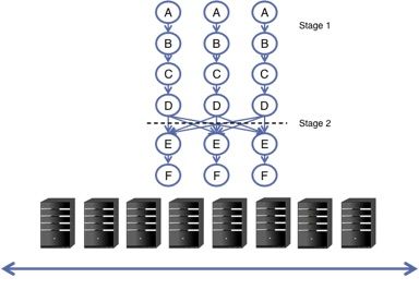
Figure 4: Apache Spark (with and without acceler-
ation)

shown in yellow boxes in this figure. The physical plan arrow
signifies the data-flow adaptation layer.
   In Figure 4, the HW accelerator template database consists
                                                                            Figure 5: Bigstream data-flow compiler
of several templates which are associated with a linear set of
operators referred to as Linear Stage Trace (LST). In other
words, LST can be considered as a subset of operators that
need to be executed sequentially within a stage. In case of          At high-level, hypervisor is responsible for picking LSTs in
FPGAs, a template includes a partially re-configurable bit           a stage, loading the right accelerator code for it (if exists),
file, which is pre-synthesized and optimized to accelerate           preparing the environment for task execution if necessary
each operator in the LST, along with meta-data for neces-            (e.g., FPGA partial programming), and executing the code
sary run-time configurations. In case of GPUs, a template            on the accelerator device.
includes CUDA/OpenCL binaries that implement the oper-                  Now we will describe run-time components in hypervi-
ators in the LST. In case of CPUs, our templates consist of          sor for the same example shown in Figure 3. Figure 6 il-
native (C++) code which links to our optimized libraries.            lustrates the acceleration of the first stage of this sample
There is a cost function that determines which LSTs need             query. As shown in Figure 3, the first stage includes opera-
to be implemented on accelerators. This cost function is             tors A, B, C and D. There can be multiple LSTs associated
tuned by offline profiling of different operators in produc-         with a stage since there are multiple combinations of sub-
tion ETL pipelines and SQL pipelines and it is tuned to be           sets available for a linear set of operators. For example, if
more effective by adding new profiling data over time.               a stage has three operators X, Y and Z that need to be
   The adaptation layer interacts with Spark query compiler          executed sequentially, then any possible sequential combi-
and converts the output of Spark query compiler, known               nation of LSTs can provide the optimal performance. For
as physical plan to a canonical data-flow intermediate rep-          example, based on data size, operator type, any combination
resentation. This canonical representation is given to our           of LST{X,Y } or LST{X} or LST{X,Y,Z} can provide best per-
data-flow compiler, and based on accelerator template avail-         formance in a Stage. In our example, Stage 1 can be repre-
ability, it generates accelerator code which can communicate         sented by (LST{A,B} , LST{C,D} ), or (LST{A} , LST{B,C,D} ),
with available accelerators (e.g., FPGA and GPU) and will            or (LST{A} , LST{B} , LST{C} , LST{D} ), etc.
be running on each executor. If data-flow compiler decides              Assume our data-flow compiler finds FPGA accelerators
not to accelerate a stage, that stage will be executed through       for LST{A} , LST{C} , and LST{D} . It also finds a native ac-
the original Spark execution path.                                   celerator for LST{B} . This means that operators A, C, and
   Figure 5 shows more details on the steps taken by data-           D will be executed on FPGA, while operator B will be exe-
flow compiler:                                                       cuted on a CPU by native code. In Figure 6, a list and order
   • Slicing and mapping: Based on LSTs in each stage of             of LSTs that are going to be executed at each time is deter-
     the query plan and matching accelerator templates in            mined by Execute Stage Task step. In our example, it picks
     template database, our compiler maps each part of the           LST{A} first. Since this LST can be executed on FPGA,
     query plan to different computational resources (e.g.,          the hypervisor programs the bit file from the template and
     FPGA, GPU, CPU, etc.). The cost function for each               it configures the FPGA with specific parameters from the
     operator helps choose the best accelerator match for            template. Then it executes LST{A} on the FPGA. Accord-
     each LST in a physical plan.                                    ing to data-flow compiler, the next LST would be LST{B} .
                                                                     Since this LST has a native template, it will be executed
   • Control plane generation: The part of the code gener-           on the CPU with our native libraries. LST{C} is the next
     ated for transitioning the control flow between LSTs            to be picked. Based on operator functionality, the current
     and the Spark task.                                             programmed template (in this case, template for LST{A} )
                                                                     cannot be reused for LST{C} . Therefore re-programming
   • Data plane generation: The part of the code generated
                                                                     the bit file and parameter configuration need to be done for
     for moving the data between LSTs and the Spark task.
                                                                     this LST. The next in the list is LST{D} . Let’s assume that
  As a result of data-flow compiler, an accelerator code is          the operator functionality for current programmed template
generated and it is ready to be executed by hypervisor layer.        (i.e., LST{C} ) can be re-used for LST{D} . For example, both

                                                                 4
Figure 7: Bigstream Hardware Abstraction Layers
Figure 6: Bigstream hypervisor run-time flow
LST{C} and LST{D} could be filter operators and therefore
we could reuse the template. Therefore, hypervisor skips bit
file programming step and only performs parameter config-
uration and runs LST{D} on FPGA. Since LST{D} is the
last one, the result will be considered as Stage 1 result. The
same flow is repeated for Stage 2 of Figure 4. For this stage, Figure 8: Bigstream hardware - software interface
the data-flow compiler finds a template for LST{E,F} , which
can be executed on the FPGA, as the most cost-optimized
option. The hypervisor takes LST{E,F} as the first LST on The partially re-configurable component of the design is
the list. Then it checks if the current programmed bit file the core region. The core corresponds to SQL, machine
can be re-used by this LST. In this example, it cannot be learning and deep-learning operators or a subset of oper-
re-used and the bit file for LST{E,F} is programmed into the ators that can be mapped and accelerated in FPGA. The
FPGA and the parameters are configured for it. Then the core region, which includes RTL IPs, is converted to RTL
hypervisor executes operators E and then F on the FPGA. Kernels in Xilinx SDAccel Development Environment [4].
Since this LST is the last LST in the list of Stage 2 LSTs, the This enables us to use the same software interface model as
results will be considered as the results for Stage 2. All of OpenCL instantiated kernels. Based on the area constraints
the above hypervisor steps, discussed in the above example, of the FPGA, our core region can consist of multiple RTL
are executed as a Spark task running on a Spark executor. kernels. The independent RTL kernels operate on mutu-
This section focused on the flow of accelerated query exe- ally exclusive partitions of data. These RTL Kernels can be
cution in Spark. In the next section, we will focus more on considered as logically equivalent of having multiple inde-
the architecture of our FPGA accelerators. pendent cores in a processor.
5. FPGA SOLUTION ARCHITECTURE 6. SOFTWARE INTERFACE FOR FPGA
As shown in Figure 7, the hardware components of FPGA BASED ACCELERATORS
can be split into three sections logically: shell, shim, and As discussed in Section 4.1, the data-flow compiler is re-
core. The shell region has fixed IP components that interact sponsible for generating codes for specific accelerators like
outside of FPGA, such as PCIe controller, DMA controller, FPGAs and the hypervisor is responsible for executing the
DRAM controller, Ethernet controller, etc. It is typically generated codes on the accelerators. The hypervisor layer
provided by FPGA vendor. The next layer in question is communicates to low level device-specific drivers through an
our proprietary shim layer, which converts external bus in- interface class which has a fixed set of APIs that are called
terfaces to compatible interfaces for our core. An example of at run-time by any operator that wishes to use FPGA. The
this is converting from memory mapped interface to stream- translation of these API calls to device-specific drivers is
ing interface which is the most common interface in our tem- handled through Bigstream’s HAL or Hardware Abstraction
plates. The shim layer also collects error and performance Layer. As shown in Figure 8, these API calls that abstract
metrics from the core. away device-specific drivers are being standardized through
5an open-API initiative, or OHAI (Open Hyper Accelera- OpenCL calls as non-blocking and asynchronous, in order
tion Initiative) that will be published in the near future. to issue multiple commands to both command queues on
These API calls belong to an interface class called OHAI a single thread effectively. This also reduces CPU utiliza-
class interface. Each Spark executor can potentially have tion by avoiding polling/busy-waiting. Another optimiza-
a SQL operator in every stage that instantiates the OHAI tion tool provided by Xilinx is to use the Embedded Run
class interface to accelerate on FPGA. As shown in Figure 8 Time (ERT) option which reduces polling on the CPU side
for Vendor C, we also support accelerating Spark streaming by moving the polling to the ARM processor in the FPGA.
applications by processing TCP/IP based packets in FPGA. We will discuss our results with respect to JSON data for-
All such interfaces contend to access resources of FPGA. We mat which is one of the predominant row based formats used
have implemented a priority round-robin scheduling to grant in big data analytics.
access to FPGA resources. The software and hardware inter-
faces were originally targeted for offload mode of processing,
in which data is brought to host memory and then send to 8. EVALUATION
FPGA for compute acceleration. In this mode, FPGA can Our testbed consists of 5 servers with 1 driver node and
be logically considered to be a co-processor to CPU cores, 4 worker nodes with SmartSSD attached to the PCIe slot.
sharing host memory with them. Each server contains Intel Xeon Gold 6152 CPU operating
at 2.10GHz with 22 physical cores in dual sockets. Each
server contains 128 GB DRAM and the servers are connected
7. DEVELOPING TEMPLATES through 10Gbps network. Figure 10 compares performance
FOR SMARTSSD of scan heavy TPC-DS queries between vanilla Spark and
This section discusses adapting our templates for SmartSSD Bigstream accelerated Spark in SmartSSD for a single node.
and associated optimization necessary for high performance. These measurements were made after all the aforementioned
With reference to the hardware logical layers in Figure 7, hardware optimizations and the results presented are end-
the shell layer for SmartSSD is provided by Xilinx. Our shim to-end query time for 200SF(200GB) data. As is observable
layer, designed for offload mode, needed a minor modifica- from Figure 10, most queries achieve around 6x acceleration
tion on the DRAM interfaces to adapt to P2P shell. Our with respect to Spark. The number of Spark executors was
kernels consume Spark data partitions from FPGA GAM set to 6 with a total executor memory of 100GB. We decided
and send the processed data back to host memory in a for- on the executor count being 6 for one SSD as a comparable
mat similar to Tungsten [19] rows, which is an in-memory equivalent to one SmartSSD. The top-15 queries are pre-
format used in Spark. For interoperability, all our row based sented for both cases separately since they are not the same
hardware templates process data internally in a similar for- subset for both of them and the baseline Spark performance
mat. We ported multiple of these row based templates to also varies between SmartSSD and SATA connected SSD.
SmartSSD so that based on the query being processed we Figure 11 shows results for a 4 node cluster with each node
can reconfigure the core region. All templates in the core re- having 100GB of TPC-DS data totaling 400GB for the clus-
ceive data to process from FPGA GAM and send the result ter. The acceleration numbers here are similar to that of
back to FPGA DRAM. After porting our design, the con- a single node cluster. In cluster mode, data is distributed
figurable logic blocks (CLB) utilization was 52% to 64% for across SmartSSD of each node and scan operation and op-
our designs with the core region operating at 200Mhz for erators succeeding scan are processed in SmartSSD. Once
the row-based templates with three kernels. As explained the scan stage is complete, shuffle data is also placed in
in Section 4, a query can pick different templates based on SmartSSD so that it can be redistributed to other nodes.
application requirements and the cost function of the tem- The average acceleration across all TPC-DS is 4.08x with
plate. On the software side, changes are necessary to make respect to vanilla Spark.
sure that data partitions generated by Spark are read into Another important advantage of SmartSSD is lower CPU
P2P GAM as opposed to host memory in the offload im- utilization which is illustrated through time-line graph of
plementation. This required adding a Spark partition file user utilization obtained through Grafana [2] in Figure 9
receiver specifically targeted for P2P transfer. In the case for Query 69. The left side of the graph shows CPU utiliza-
of accelerated Spark, for the scan operator, we issue a P2P tion of executors in our accelerated Spark. The right side
read to transfer the data from SSD to FPGA GAM and shows CPU utilization of vanilla spark executors. The peak
once the data transfer is complete we enqueue an OpenCL CPU utilization of our version is less than 30% while that
compute task to operate on the data in GAM. of Spark is around 90% for the cores executing the query.
Across all TPC-DS scan heavy queries, we observed that
7.1 Performance Optimization CPU utilization was similarly low for SmartSSD. In produc-
An important optimization that is necessary for good per- tion environments, with multi-tenancy support, lower CPU
formance is to decouple the P2P command queue from com- utilization could lead to more workloads being run on the
pute command queue. This is necessary because we can have same machine through different containers.
data transfers initiated to the FPGA GAM region through
P2P command queue, while the compute command queue
is being processed on another GAM region. A further opti- 9. FUTURE WORK
mization is to use asynchronous read for P2P as opposed to We have presented results that show significant run-time
synchronous read so that a single thread can operate on both speedup over Apache Spark, based on our row based de-
P2P and compute command queue. Since Xilinx drivers sup- sign. In our final product, which is under quality control
port POSIX API for P2P read, we used aio read as opposed and testing, we are using more SSDs in the system and we
to pread or read [3]. This also enables us to have all our are observing that the performance scales across executors
6Figure 9: CPU utilization - Spark vs XSD
Figure 10: Row Based acceleration results for Top 15 TPC-DS scan heavy queries with SmartSSD
and SmartSSDs. In our future work, we will present com- from higher performance, we also gain total cost of owner-
prehensive results on columnar formats such as Parquet and ship (TCO) savings when using our accelerated platform on
ORC. On the hardware side, we are actively working on in- SmartSSD. Two main reasons for TCO saving are: 1) CPU
creasing the number of templates available in SmartSSDs utilization drops dramatically during our accelerated Spark
by including solutions such as DNN and machine learning with SmartSSD, specifically during scan stages. This drop
pipelines [20], cryptographic and hashing templates, etc. We leads to shorter tenant run-time and enables more container-
are also working on pushing the frequency of our kernels ized processes in a multi-tenant environment. 2) SmartSSD
along with the number of kernels. On the software side, we consumes lower power than adding more cores to a proces-
are working on adding support for frameworks like Hive and sor which adds up to a significant amount of energy saving
Kafka KSQL to take advantage of our hyper-acceleration in modern data-centers.
layer which now supports SmartSSD as well as traditional The hardware, that we are working with, is a pre-production
FPGA architectures. part and we are confident of improving performance with our
next generation of software and hardware IPs targeted for
the production part. The production version of SmartSSD is
10. CONCLUSION a PCIe U.2 attached card, which is more tightly integrated
In this paper, we have explained our framework for accel- with improved bandwidth and SSD capacity.
erating Big Data platforms on computational storage. We
chose Samsung SmartSSD which enables performing compu-
tation close to storage and have shown significant query run- 11. ACKNOWLEDGMENTS
time speedup for TPC-DS benchmarks for row-based format We would like to thank Xilinx and Samsung for provid-
on SmartSSD, compared to Apache Spark. Our results also ing us access to pre-production parts of Xilinx DSA and
scale when we move from single node to multi-node. Apart SmartSSD. We would like to thank Gopi Jandhyala, Sebas-
7Figure 11: 4 node cluster results for Top 15 TPC-DS with 400 GB data with SmartSSD
tian Turullols from Xilinx and Vish Maram, Pankaj Mehra, [8] What is a hypervisor. https://www.vmware.com/
Fred Worley and Bob Napaa from Samsung. We would also topics/glossary/content/hypervisor,visited
like to thank Weiwei Chen, John Davis, Gowtham Chan- 2019-06-02.
drasekaran, Brian Hirano, Roop Ganguly, Chris Ogle, Chris [9] M. Armbrust, Y. Huai, C. Liang, R. S. Xin, and
Both and Danesh Tavana for support in this work. M. Zaharia. Deep dive into spark sql’s catalyst
optimizer.
12. ADDITIONAL AUTHORS https://databricks.com/blog/2015/04/13/deep-
dive-into-spark-sqls-catalyst-optimizer.html,
visited 2019-06-02.
13. REFERENCES [10] S. Boboila, Y. Kim, S. S. Vazhkudai, P. Desnoyers,
[1] Computational storage technical work group. and G. M. Shipman. Active flash: Out-of-core data
https://www.snia.org/computational, visited analytics on flash storage. In 012 IEEE 28th
2019-06-02. Symposium on Mass Storage Systems and
[2] Grafana labs. 2018. grafana – the open platform for Technologies (MSST), pages 1–12. IEEE, 2012.
analytics and monitoring. https://grafana.com, [11] J. Do, Y.-S. Kee, J. M. Patel, C. Park, K. Park, and
visited 2019-06-02. D. J. DeWitt. Query processing on smart ssds:
[3] The open group base specifications issue 7. opportunities and challenges. In Proceedings of the
https://pubs.opengroup.org/onlinepubs/ 2013 ACM SIGMOD International Conference on
9699919799.2018edition/, visited 2019-06-02. Management of Data, pages 1221–1230. ACM, 2013.
[4] SDAccel development environment help for 2018.3. [12] J. Fifield, R. Keryell, H. Ratigner, H. Styles, and
https://www.xilinx.com/html docs/xilinx2018 3/ J. Wu. Optimizing opencl applications on xilinx fpga.
sdaccel doc/creating-rtl-kernels- In Proceedings of the 4th International Workshop on
qnk1504034323350.html, visited 2019-06-02. OpenCL, page 5. ACM, 2016.
[5] SmartSSD, faster time to insight. [13] P. Francisco et al. The netezza data appliance
https://samsungatfirst.com/smartssd/, visited architecture: A platform for high performance data
2019-06-02. warehousing and analytics, 2011.
[6] TPC-DS. http://www.tpc.org/tpcds/, visited [14] B. Gu, A. S. Yoon, D.-H. Bae, I. Jo, J. Lee, J. Yoon,
2019-06-02. J.-U. Kang, M. Kwon, C. Yoon, S. Cho, et al. Biscuit:
[7] An update on data center fpgas. A framework for near-data processing of big data
https://www.forbes.com/sites/moorinsights/2018/ workloads. In ACM SIGARCH Computer Architecture
07/20/an-update-on-data-center-fpgas/ News, volume 44, pages 153–165. IEEE Press, 2016.
#4fcff99346c2,visited 2019-06-02. [15] Y. Kang, Y.-s. Kee, E. L. Miller, and C. Park.
Enabling cost-effective data processing with smart ssd.
8In 2013 IEEE 29th symposium on mass storage visited 2019-06-02.
systems and technologies (MSST), pages 1–12. IEEE, [20] H. Sharma, J. Park, E. Amaro, B. Thwaites,
2013. P. Kotha, A. Gupta, J. K. Kim, A. Mishra, and
[16] K. Keeton, D. A. Patterson, and J. M. Hellerstein. A H. Esmaeilzadeh. Dnnweaver: From high-level deep
case for intelligent disks (idisks). ACM SIGMOD network models to fpga acceleration. In the Workshop
Record, 27(3):42–52, 1998. on Cognitive Architectures, 2016.
[17] E. Riedel, C. Faloutsos, G. A. Gibson, and D. Nagle. [21] J. Wang, D. Park, Y.-S. Kee, Y. Papakonstantinou,
Active disks for large-scale data processing. Computer, and S. Swanson. Ssd in-storage computing for list
34(6):68–74, 2001. intersection. In Proceedings of the 12th International
[18] E. Riedel, G. Gibson, and C. Faloutsos. Active storage Workshop on Data Management on New Hardware,
for large-scale data mining and multimedia page 4. ACM, 2016.
applications. In Proceedings of 24th Conference on [22] M. Zaharia, R. S. Xin, P. Wendell, T. Das,
Very Large Databases, pages 62–73. Citeseer, 1998. M. Armbrust, A. Dave, X. Meng, J. Rosen,
[19] J. Rosen. Deep dive into project tungsten: Bringing S. Venkataraman, M. J. Franklin, A. Ghodsi,
spark closer to bare metal. jun. 16, 2015. https:// J. Gonzalez, S. Shenker, and I. Stoica. Apache spark:
databricks.com/session/deep-dive-into-project- A unified engine for big data processing. Commun.
tungsten-bringing-spark-closer-to-bare-metal, ACM, 59(11):56–65, Oct. 2016.
9You can also read