Current challenges in modelling vibrational fatigue and fracture of structures: a review
←
→
Page content transcription
If your browser does not render page correctly, please read the page content below
Journal of the Brazilian Society of Mechanical Sciences and Engineering (2021) 43:77
https://doi.org/10.1007/s40430-020-02777-6

 REVIEW

Current challenges in modelling vibrational fatigue and fracture
of structures: a review
Khangamlung Kamei1 · Muhammad A. Khan1

Received: 26 July 2020 / Accepted: 15 December 2020
© The Author(s) 2021

Abstract
Fatigue damage is a concern in the engineering applications particularly for metal structures. The design phase of a structure
considers factors that can prevent or delay the fatigue and fracture failures and increase its working life. This paper compiled
some of the past efforts to share the modelling challenges. It provides an overview on the existing research complexities in
the area of fatigue and fracture modelling. This paper reviews the previous research work under five prominent challenges:
assessing fatigue damage accurately under the vibration-based loads, complications in fatigue and fracture life estimation,
intricacy in fatigue crack propagation, quantification of cracks and stochastic response of structure under thermal environ-
ment. In the conclusion, the authors have suggested new directions of work that still require comprehensive research efforts
to bridge the existing gap in the current academic domain due to the highlighted challenges.

Keywords Crack quantification · Elevated temperature · Couple loads · Thermal properties · Structural dynamics

1 Introduction changing needs of the people. A number of review articles
 published related to fatigue and fracture: thermal loadings
In engineering world, crack occurrence and propagation in fracture of shape memory alloys [2], multiaxial vibration of
the material components and the structures are serious issues linear and nonlinear systems [3], variable amplitude fatigue
to address. Failure in early detection has consequences lead- [4], interpretive technical history of fracture mechanics [1],
ing to catastrophic damage. The catastrophic failure is cost role of dynamic response parameters in damage prediction
to bear as the machineries are expensive and not easily [5], cumulative fatigue damage mechanisms and quantifying
replaceable rather to be repaired. For this reason, academi- parameters [6], stability and significance of residual stress
cians have performed extensive research to find solutions during fatigue [7]. The existing reviews somehow managed
and minimize the crack growth. to explain the details about the micromechanics of fatigue
 Engineering materials, especially metals, develop cracks and fracture and the macroscopic behaviour of the struc-
and fracture during their service time. In most of the applica- ture distinctly separate. However, these details are unable
tions, such as automotive, aircrafts and power plant, operate to address a good number of modelling challenges which
under high temperatures. Such structures and components of can come across if the mentioned mechanics and behaviour
the machine develop crack more prevalent under the com- will be correlated.
bined effect of thermal and mechanical loads and experi- These challenges are still unaddressed, especially when
ence fatigue. Although the knowledge of the fracture and the loads are no more singular and quasi-static in nature. The
fatigue was confirmed in 1754 BC [1], the scientific society couple loads dynamic in nature involve mechanical and ther-
faced many challenges while considering the continuous mal external disturbances, and this duality in time domain
 creates complexity in analytical mathematics to solve the
 real phenomenon on structure with exactness.
Technical Editor: João Marciano Laredo dos Reis.
 This paper compiled some of the past efforts to share the
* Khangamlung Kamei aforesaid challenges. It provides an overview on the exist-
 k.kamei@cranfield.ac.uk ing research complexities in the area of fatigue and fracture
 modelling. This paper reviews the previous research work
1
 Through-Life Engineering Services Institute, Cranfield under five prominent challenges: assessing fatigue damage
 University, Bedford MK43 0AL, UK

 13
 Vol.:(0123456789)
77 Page 2 of 20 Journal of the Brazilian Society of Mechanical Sciences and Engineering (2021) 43:77

accurately under the vibration-based loads, complications in ratio. Julien et al. [33] and Kitipornchai et al. [34] exam-
fatigue and fracture life estimation, intricacy in fatigue crack ined probabilistic random vibration. They concluded that
propagation, quantification of cracks and stochastic response the linear frequency dispersion is an influence of change in
of structure under thermal environment. In the conclusion, temperature. Rezaee et al. [35] studied vibration analysis of
the authors have suggested new directions of work that still nano-wires and Ubertini [36], and Bao et al. [37] studied
require comprehensive research efforts to bridge the existing vibrations of bridge structures. A few of the articles reported
gap in the current academic domain due to the highlighted fatigue due to vibration [38–40] and predominantly based on
challenges. applications. These suggest the assessment of fatigue dam-
 age is on weak foundation due to lack of analytical relations
 and arguments, especially when the structures are operated
2 Challenge‑1: assessing fatigue damage under thermomechanical loads.
 accurately under the vibration‑based Modal analysis is a common method to predict the struc-
 loads tural health based on experimentally measured vibrations
 [41]. This method is more often used for extracting defects
Thermomechanical vibrations have been concerned for the and faults from structural applications, which are too com-
engineering applications. In the growing advancement of plex to model analytically and numerically, for example
technology, these applications exposed to the mechanical modal analysis of exhaust manifold in hot condition [42],
loads under thermal conditions and has tendered the sci- the turbine blade at complex thermomechanical loads [43],
entists and engineers to investigate the dynamic behaviour high-speed machine-like servo-hydraulic [44], jet engine
of structures and their components [8]. The vibration of fan [45], extracting full-field dynamic strain subjected to
the components influences the durability and reliability. arbitrary excitations on a wind turbine rotor [46], etc. Modal
Generally, vibration is analysed in four domains and each analysis can also determine the dynamic stress intensity
domain offers identifiable data on the operational condi- factor [47]. Similarly, it is also utilized in different other
tions and characteristics of the vibration [9]. Researchers approaches. Jezequel [48] used a hybrid method of modal
apply different theories to study the characteristics of vibra- synthesis using the vibration tests. The method approved to
tion: higher-order shear deformation theory [10–14], non- be helping in studying the structuring modification. Yam
local elastic theory [15, 16], modified couple stress theory et al. [49] experimentally studied and suggested that modal
[17], generalized differential quadrature method [18], Bub- strain analysis can be effectively utilized to study structural
nov–Galerkin method [19], thermal-energy method [20], dynamic and fatigue life estimation. Haider and Nayfeh [50]
finite element analysis [21, 22] among many others. Most of investigated the modal interaction in the nonlinear forced
these methods are, however, purely analysing the vibrational vibrations of a heated plate. Lamb and Rouillard [51]
characteristic behaviour of the structure without concerning stated that system fatigue characteristic can be obtained by
the fatigue damage. Assessment of fatigue damage under monitoring its modal parameters. Braghin et al. [52] modal
such condition is still a concern and challenge. Further the control technique is new to the mechanical and structural
current investigations on thermomechanical vibration are engineers due to it modal coordinate representations. Nev-
more focused on different materials: materials like graphene ertheless, modal analysis has limited over the applied bound-
sheet [23, 24], functional graded nano-plate [25], compos- ary conditions which compromises the real-case scenario.
ite beams [26] and nano-composite plate [27]. Primarily, it Thermomechanical vibration examinations are important
is on application-based studies rather than emphasizing in to establish failure possibilities and crack propagation before
accurate measurement of the fatigue. catastrophic failure. In the past, researches used the system
 Warminska et al. [28] demonstrated that structural dynamic response and predicted the possible faults, defect
response is directed by the level of thermal loading and and their conceivable locations [8]. Mathan and Prased [53]
distribution. A large increase in temperature can shift the studied the dynamic response of the piping system at various
vibration centre and it affects the fundamental frequency. temperatures using finite element analysis. They performed
Yang and Shen [29] studied in similar way confirmed the FE simulation with the help of modal and harmonic analysis.
vibration response as a result of thermal effect, material Experiments and numerical simulations were also performed
composition, boundary condition and loading mode. A free to study the dynamic and acoustic response of clamped rec-
vibration analysis in cylindrical bodies highlighted the fre- tangular plate and of a composite structure [54, 55]. The
quency vibration depends on mode, thickness and curvature flexural responses of a thermoelastic thin beam were also
of structure [30]. Shen and Wang [31] and Ghayesh et al. studied under thermal and mechanical load [56]. Shen et al.
[32] investigated on nonlinear vibration. They noticed the [57] studied Reissner–Mindlin plate resting elastic foun-
increase in temperature minimized the natural frequency dations. Beside the mentioned, researchers evaluated the
but has marginal effect on nonlinear-to-linear frequency vibration modes using video measurements [58]. It is well

13
Journal of the Brazilian Society of Mechanical Sciences and Engineering (2021) 43:77 Page 3 of 20 77

established that the academics studied vibration behaviour af
 da
of structures of different sizes, thicknesses and layers, i.e. N=∫ (2)
 ao CΔK m
sandwich plates [59–61]. Furthermore, the study of vibra-
tion in the finite element method becomes familiar among Damir et al. [81] proved that modal analysis is a great
the researchers due to cost-effective and ease of evaluating potential for fatigue evaluation and characterization of the
the data. Nevertheless, the data obtained from experiments mechanical components. This investigation determined the
are always far from an agreement with the simulation results capability of experimental modal analysis as a non-destruc-
due to practical compromises [62]. tive tool. Braceesi et al. [74] used the modal frequency
 domain approach to evaluate the virtual fatigue life in a non-
 linear system. They considered the random loads to estimate
 the component life considering the dynamic behaviour and
3 Challenge‑2: complications in fatigue state of stress. The fatigue damage due to the stress time
 and fracture life estimation history was acquired by augmenting the Gaussian damage
 (Dg ). However, in real situation damage is non-Gaussian.
Fatigue is a failure phenomenon in materials that involves
 The use of corrective coefficient of non-Gaussianity, ng to
cyclic load with developing cracks [63, 64]. Fatigue nor-
 estimate the non-Gaussian damage, Dng is given by Eq. (3).
mally occurs when a repeated or fluctuating load applied,
which may either or both tensile, compressive or torsional. Dng = ng Dg (3)
There are three stages in fatigue life [65]: crack initiation,
crack propagation and failure stage. The crack initiates Using the Goodman symmetric law, the functional rela-
where there are discontinuities in the crystal structure of tion for the corrective coefficient is developed in the form
the material. The development of the discontinuity actually of Eq. (4).
strengthens the structure through plastic deformation but lost ng = f ( , , Sk, Ku, m) (4)
its ability after reaching deformation limit and thereafter
developed minute crack [62]. The slow and steadily growth where m is the material constant of Wöhler’s curve, is
of a crack threatens the structural integrity. The final stage mean value, Sk is skewness and Ku is kurtosis. The Gauss-
of crack development is fatigue failure. The fatigue life is ian damage curve in given Eq. (5) was used to analyse the
dependent upon the load history, residual stresses, properties fatigue damage.
of the material, manufacturing defects, grain size, design
 3
geometry, environmental conditions, etc. Studies on the ther-
 ( )
 m2 (Ku − 3) Sk2
 ng = e − (5)
momechanical fatigue [66–73] are limited to some applica- 5 4
tions and need comprehensive assessment, in particular, for
fatigue life estimation. The following section discusses the In another papers of Braccesi [75, 82], a modal approach
fatigue life estimation methods to highlight the unaddressed was used to evaluate the frequency domain stress recovery
challenges. and fatigue damage of mechanical components. The stress
 tensor of the model was obtained from the power spectral
 density matrix. In Dirlik’s method, the fatigue damage D
3.1 Life estimation methods was calculated by the relation of Eq. (6).

Knowing the life of the component before being used is T.nt ∞
 D= ∫ (Δ )k .f (Δ )d(Δ ) (6)
the most important aspect to avoid fatigue or catastrophic C 0
failure. There are number of methods and techniques to
predict the fatigue life. Approaches like frequency domain where T is the duration of the random signal application,
method [74, 75], modal approach [40, 47, 72], accumula- nt is the number of cycles per unit time, (Δ )k probability
tive approach [76], thermal fracture model [77], continuum density function of the stress range and f (Δ ) is frequency
mechanics model [78] and intrinsic dissipation model [79] domain criteria. The other method of calculating fatigue
are predominant. The foremost and well-known method was damage is Bands method given by the relation of Eq. (7).
formulated by Paris and Erdogan [80] given in Eq. (1). 1
 K. .fref
da D= (7)
 = CΔK m (1) 1∕
dN (∫ Gref (f )df ) 2

where ΔK the stress intensity range, C and m are the material where the functions K parameters and are from the
constants. The fatigue life is then determined by integration Wöhler’ curve, fref is reference frequency and Gref (f ) is the
as in Eq. (2). ratio function.

 13
77 Page 4 of 20 Journal of the Brazilian Society of Mechanical Sciences and Engineering (2021) 43:77

 In non-local-based fatigue life estimation, the dispersal where R is the average failure function, n, ns are normal
of stress/strain in the locality of the crack tip is estimated and shear stresses on the physical plane, the critical distance
[83]. The non-local damage parameter is the integration d0 in area method is calculated by Eq. (14).
of all local damage parameter in the material domain. The
 )2
local parameters are however estimated from the classical KI,th
 (
 2
mechanics without considering the material homogeneity.
 d0 = (14)
 af
The non-local concept considered the complexity of the
geometry structure by analysing the influence of inhomoge- The volumetric method assumes that fatigue failure is
neity stress field [84]. This approach is termed as critical dis- due to the damage parameter over a critical volume. Sain-
tance method. The local parameter is estimated by a point, a tier et al. [85] proposed a non-local energy-based fatigue
line, an area or volume. The local parameter is calculated by: life calculation subjected to multiaxial variable amplitude
 loading. They anticipated two hypotheses of volumetric
 1
 damage parameters. The volumetric damage parameters are
 ( ) ( )
 eff t, ro = ( ) ∫ n (t, r)w r − ro dA (8)
 ŵ ro A expressed as:
 ( ) 1
 geq, dam Ci = ( ) ∫ Wgeq,dam dV
 ( ) ( )
ŵ ro = ∫ w r − ro dA (9) V∗ Ci v∗ (Ci ) (15)
 A

where t is the time, r is the unit vector and ro is the reference where geq, dam is the non-local damage parameter, V ∗ is the
point in the crack tip and A is the critical plane area. The volume influencing fatigue crack initiation, Ci is the potential
weight function is presented in Eq. (10). critical point and Wgeq,dam is damaging strain energy density.
 ( )2
 2r The final energy damage parameters S–N curve equation is
w(r) = exp
 − (10)
 lc
 given as:
where r = ||r − ro || and lc is the critical length. (
 C∕
 )2
 In the point method, the fatigue failure occurs because of N − ( ∗ )2
 (16)
 geq, dam (N) =
the presence of stress/strain to some critical distance from E
the crack tip. It is considered as non-local since the selected
 where E is Young modulus, ∗ is threshold stress, N is num-
point is not from the crack-tip region. The fatigue life is cal-
 ber of cycles, C and are material constant.
culated by reducing the stress/strain into equivalent stress/
 Another technique of evaluating fatigue damage is
strain parameters. The critical distance is calculated [83]
 the accumulative approach. This technique is known as
by Eq. (11).
 Palmgren–Miner rule which is a linear damage accumulation
 1
 (
 ΔKI,th
 )2 rule. It states that failure occurs when the fatigue damage D
Dc = (11) is equal to unity.
 Δ af
 ∑ ni
where ΔKI,th is a range of threshold value of stress intensity D= =1 (17)
 Ni
factor and Δ af is the range of fatigue limit.
 The line method assumes that fatigue failure is due to the Palmgren–Miner rule is, however, not suitable for non-
presence of stress over the line. The average of the stress is linear damage. Proso et al. [38] proposed the damage accu-
calculated as: mulation correction rule for structural nonlinearity. The cor-
 rected damage accumulation is estimated by the following
 1 D relation:
 af = ∫ w(x)dx (12)
 D0 y ∑
 Dc = Di .Rni = 1 (18)
where D is the distance from the notch point and w(x) is the i
weight function.
 The area method assumes that failure is due to the dam- where R is the constant correction factor and n is the rate of
age parameter over some area. The average failure function nonlinearity which is obtained experimentally. The fatigue
is calculated by: damage is calculated by Eq. (19).

 1 ( ) ∑ ni ∑ ti
R = ∫ R n , ns dA (13) D=1= Di = (19)
 2
 d0 A Ni Ti

13
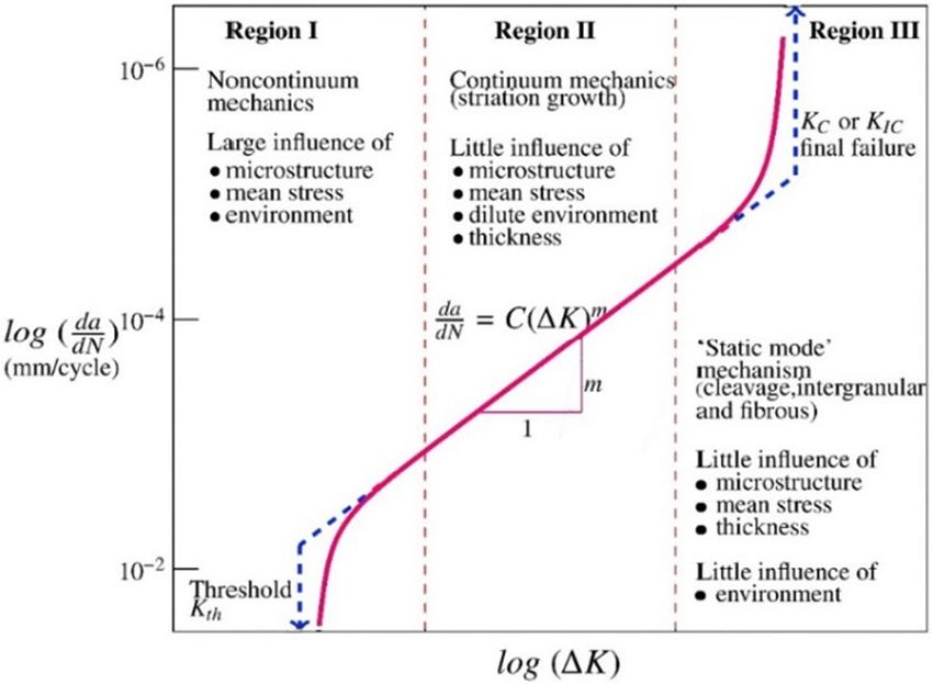
Journal of the Brazilian Society of Mechanical Sciences and Engineering (2021) 43:77 Page 5 of 20 77

where ti and Ti are, respectively, the time of excitation the stress intensity factor. In other papers of same authors
and fatigue lifetime. There are several factors, which are [104, 105], crack growth retardation was applied with the
responsible for nonlinear damage mechanisms. The effects help of a stop hole at the crack tip. These investigations
of overloading and geometrical discontinuities are pre- demonstrated an extension in the overall fatigue life. All
dominately studied in the existing literature [86–88]. The these studies specify despite numerous concept of fatigue
nonlinear nature of fatigue damage due to overloading and life estimation, it is hypothetically demanding to locate the
under loading creates irregular local stress amplitude near perfect explanation and amplification.
the crack tip. However, damage evolution due to overload
is also dependent on the nature of the microstructure which
can be improved by the heat treatment processes [87]. The 4 Challenge‑3: intricacy in fatigue crack
geometrical discontinuities affect the fatigue life due to propagation
stress concentration. These discontinuities are inevitable in
the structures mainly due to design requirements. However, A fatigue crack growth curve is a graphical representation
researchers do relate their influence with microstructural of the stress intensity factor range and cracks growth rate
voids, corrosion pits, riveting joints, wear and tear [89–91]. [63, 64]. The region I describe the crack initiation which
Therefore, these discontinuities can lead a nonlinear damage is termed as near-threshold zone below which the fatigue
progression. crack does not happen. Region II is the intermediary zone
 There are other approaches to fatigue life estimation mod- where there is linear and steady crack propagation occur
elling found in articles: thermal fracture modelling method appropriated for Paris and Walker models. The abnormal
for functionally grade plate [77], continuum mechanics fatigue crack growth occurs in the region III due to the phe-
modelling for fracture analysis [78] and intrinsic dissipation nomenon of plasticity that leads it to the catastrophic failure.
modelling for high-cycle fatigue life prediction [78]. Susmel The crack growth rate rises rapidly as the maximum stress
and Taylor [92] attempted to use a critical distance method intensity factor reaches the fracture toughness, as shown in
to estimate the finite life of notch components based on the Fig. 1. However, the crack growth rate may not be same for
modified Wöhler curve method under variable amplitude all the materials.
loading. In similar work of using a critical plane approach, The simplest form of fatigue crack growth analysis is
Gates and Fatemi [93] studied the multiaxial amplitude those which are subjected to constant amplitude loading
fatigue life of un-notch specimens. The shortcoming of the because no loading history has to be considered [64]. The
critical distance method is averaging the local parameters complexity of the crack growth evaluation arises due to
which may theoretically not precisely measured. Other the variable amplitude loading where the existing load-
researchers studied the lifetime by the simulation method. ing interaction effects. Chowdhury et al. [64] proposed
Riedler et al. [94] simulated the lifetime of thermomechani- a framework to select the fatigue crack growth method
cal loaded components which investigated the transfer- for life cycle assessment. Their paper discussed the four
ability of the simulation models to the real components. fatigue crack models, their advantages and highlighted
Khan et al. [94–96] studied the remaining life prediction the model’s limitations. Zang et al. [106] explored the
method based on the natural frequency. High-cycle and low-
cycle fatigue life prediction model was also presented for
Nickel-based single-crystal blade [97]. Researcher applied
the thermal-fatigue life assessment on real applications
[22, 39, 98–101]. Kamaya and Kawakubo [102] studied
the effect of loading sequence on fatigue life. They found
fatigue life is longer in the case of high-low loading than
low–high loading sequences. Besides, their studied found
crack mouth opening effect is the main cause in reducing
fatigue life whereas stress intensification, damage interac-
tion and damage sequence effect demonstrated less impact
on fatigue life. Several life extension techniques have been
proposed in the literature. They have made a fair impact
on the existing fatigue life estimation approaches. Ayatol-
lahi et al. [103] studied crack growth retardation technique
by introducing a drilling hole along the crack flanks. Their
numerical analysis results revealed that the presence of holes
around the crack tip reduces the stress concentration and Fig. 1 Fatigue crack growth curve [64]

 13
77 Page 6 of 20 Journal of the Brazilian Society of Mechanical Sciences and Engineering (2021) 43:77

judgement criterion of the dominant factor of creep- growth rates of fatigue, creep and creep-fatigue interac-
fatigue. They considered the interaction of creep-fatigue tion are presented in Fig. 2a–e. The crack growth rates
at different intensity factor ranges at different temperatures were compared for 0-s with 90-s dwell time at tempera-
with dwell time under various loading condition. Their tures 650 °C, 670 °C, 690 °C, 710 °C and 750 °C. The
studied highlighted that both time-dependent (creep- graphs indicated that fatigue item dominated the crack
fatigue) and cycle-dependent (fatigue) involves in the growth rates at lower temperatures and creep item has lit-
crack growth process as shown in Eq. (20). The crack tle influence in the whole stress intensity range. However,

Fig. 2 Crack growth of creep-fatigue interaction for nickel-based superalloy at a a 650 °C, b 670 °C, c 690 °C, d 710 °C and e750 °C. with 90 s
dwell time [106]

13
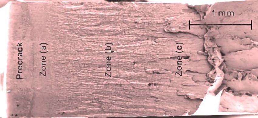
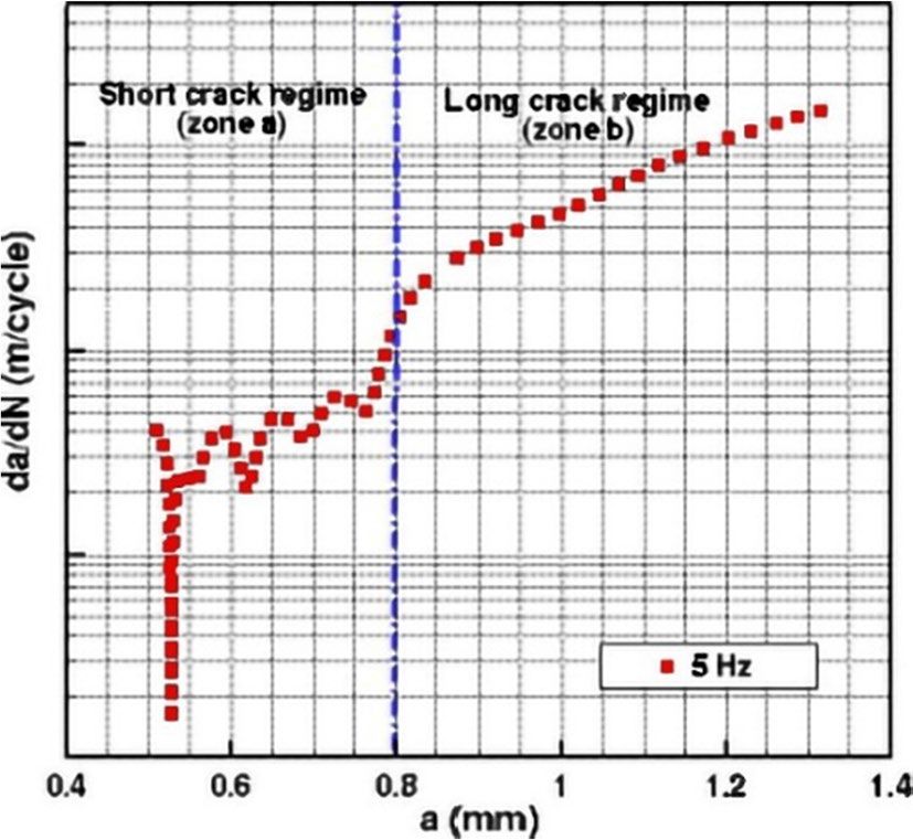
Journal of the Brazilian Society of Mechanical Sciences and Engineering (2021) 43:77 Page 7 of 20 77

Fig. 3 Shape of analysed cycles a without hold time, b with a hold
time, c and d in overloads test [110]

the creep item dominates the crack growth at higher tem-
peratures as shown in Fig. 2e.
da da da
 ( ) ( )
 = + (20) Fig. 4 Crack growth rate evolution as a function of crack length
dN dN cycle - dependent dN time - dependent increases at a frequency of 5 Hz for AM1 single-crystal super alloy
 [110]

 Crack growth tests are normally performed in iso-
thermal situations at a different temperature to illustrate
the material behaviour [107]. Fatigue crack growth rate
increases with the rise in temperature. Lu et al. [108]
studied the hold-time effect of elevated temperature crack
growth behaviour of strengthening super alloys. This
research applied the fracture mechanics parameters to
correlate the crack behaviour at a different temperatures.
The result showed that the time-dependent creep damage
mechanisms control the cracking path. Narashimhachary
et al. [109] found that there is a difference in the stress
 Fig. 5 Crack scanning electron micrographs of the fracture surface
intensity solutions for a rectangular edge-cracked plate
 from the specimen tested at 5 Hz for AM1 single-crystal super alloy
emphasizing the importance of using correct boundary [110]
conditions. Bouvard et al. [110] formulated a phenomeno-
logical model to predict the crack growth in crystal super
alloys at elevated temperatures. Fatigue and creep-fatigue
tests were taken out to inspect the consequences of time on
crack growth rates. A different form of loading conditions
was performed to examine the crack growth process for (a)
without hold time (b) hold time, (c) and (d) at overloads
as shown in Fig. 3.
 It is remarkable that the two regimes in Fig. 4 are also
viewed from the fracture surface from scanning electron
micrographs as shown in Fig. 5. The four zones are the
pre-crack, short crack regime, long crack regime and fail-
ure zone. Sankararaman et al. [111] presented a method to
quantify the uncertainty in fatigue crack growth progno-
sis which are applied to structure with complex geometry Fig. 6 Crack propagation analysis [111]
and subjected to variable amplitude multiaxial loading.
The model modified the Paris law to include the retar-
dation effects which is shown in Fig. 6. The sources of discussed model uncertainty parameters like crack growth
the uncertainty mentioned the physical variability like law, calculation of stress intensity factor, etc.
loading, initial flaw size and data uncertainty. They also Yao et al. [112] studied the effect of thermal-induced
 damage on the dynamic fracture toughness. The notch

 13
77 Page 8 of 20 Journal of the Brazilian Society of Mechanical Sciences and Engineering (2021) 43:77

specimen of two mortars were heat treated and tested the accelerated crack growth by the addition of cyclic mode
with a split Hopkinson pressure bar (SHPB). X-ray com- II. The result of mixed-mode crack growth was affected by
puter tomography (CT) was used to quantify the thermally the collaboration of plastic deformation zone, load ratio and
induced micro-crack and changes in chemical in terms of CT increase in contact area on the rough crack surface.
value. They observed that there was a decrease in fracture Fatigue crack growth rate at elevated temperature has
toughness due to the heat treatment. They found fracture studied extensively in recent past. These studies concluded
damage is a combined effect of micro-crack and deterio- that the crack propagation is caused by several factors like
ration in binding property. Kidane and Shukla [113] also environmental, stress-assisted grain boundary, oxygen
investigated the effect on a thermal and loading rate on the embrittlement [116], stress intensity factor with the effect
fracture toughness of Ti/TiB using a three-point bend speci- of frequency, load ratio and temperature [117, 118]. Wen
men. Unlike Yao et al. [112], they used the modified SHPB et al. [119] analysed the finite deformation under small creep
apparatus with an induction coil as a heating system. The condition. The crack growth rate was discovered to be more
fracture toughness was found to be sensitive to temperature sensitive to the finite element size under cyclic loading than
as shown in Fig. 7. Fracture initiation toughness was noticed monotonic loading conditions. Tvergaard and Needleman
to be strain rate sensitive and higher for dynamic loading as [120] studied the brittle–ductile transition in dynamic crack
compared to the quasi-static conditions. Verlesen and Peirs growth by considering the thermal softening and ductile
[114] investigated the fracture behaviour of Ti6A114V under failure. They established the transition from cleavage crack
quasi-static and high strain rate conditions. The fracture at a lower temperature to ductile cracked growth at a higher
behaviour was illustrated from Johnson–Cook damage ini- temperature. Nishioka et al. [121] investigated the effect of
tiation criterion combined with energy-based ductile damage specimen size on dynamic crack propagation of double can-
law. The process of void nucleation and crack growth was tilever beam. The propagating crack was observed through
unexpectedly culminated by strain localization. The strain high-speed photography. The investigation reported the val-
rate effect was experienced caused by thermal softening ues of crack arrest toughness were larger for shorter speci-
which support the strain localization. men than a longer specimen. Thus, it can be concluded that
 In past studies, fatigue crack growth was tested under the complexities in estimating crack growth are due to the
the isothermal situation. Lansinger et al. [107] attempted inconsistent crack propagation pattern.
to test the crack growth rate in the combined condition of
thermal and mechanical loading. The tests used a tempera-
ture loading frequency of 1 Hz with cooling rates of 3 to
5 °C/min. They discovered that the combined test was in 5 Challenge‑4: quantification of cracks
good agreement with the isothermal crack propagation at the
same loading frequency. Estimation of fatigue crack growth Quantification of cracks is the measurement of crack mag-
was also performed in complex loading conditions [76]. nitude. There is no such single equation which satisfies dif-
You and Lee [115] evaluated the crack behaviour of steel in ferent crack problems and their concerning boundary condi-
mixed-mode I and mode II loadings. Their studies revealed tions. However, in most cases, the researcher attempted to
 quantify cracks by calculating the state of the stress/strain
 field, residual stress and the displacement data. In many situ-
 ations, the stress intensity factor (SIF) is used to predict the
 stress state near the crack tip [122–125]. In dynamic load-
 ing, SIF is reinstated by the dynamic stress intensity factor
 (DSIF) [126–133]. In thermal loading condition, several lit-
 eratures [123, 134–148] used thermal stress intensity factor
 (TSIF) to determine the thermal stress state. Kim et al. [122]
 stated that the stress intensity factor due to the thermal loads
 is the function not only to immediate boundary conditions
 but also of the preceding history of the boundary tempera-
 ture. Stress intensity factor is nonetheless dependent on the
 state of stress/strain, displacement and temperature fields
 which are the potential factors to quantify cracks. Hence-
 forth, quantifying cracks are perplexed especially in complex
 geometrical structures. Consequently, the study of cracks
Fig. 7 Effect of temperature on the fracture initiation toughness of
FGM graded in the crack direction under quasi-static and dynamic includes classification of remote stress, orientations of the
loading [113] obtained cracks and respective material properties.

13
Journal of the Brazilian Society of Mechanical Sciences and Engineering (2021) 43:77 Page 9 of 20 77
Defining the stress intensity factor is vital to estimate
{
Etip for plane stress
accurate crack propagation. Different stress intensity fac- where Etip
∗
= Etip
2 for plane strain
tors are defined in the literature based on the boundary 1−vtip
conditions. Tran et al. [149] conducted a modal analysis to Moreover, Huang et al. [125, 153] used the domain-inde-
compute stress intensity factor. Modal stress intensity fac- pendent interaction integral method to evaluate the DSIF for
tor was extracted from stationary crack and computed the crack with nonhomogeneous materials. The relationship is
dynamic stress intensity factor using the extended finite ele- given in Eq. (25).
ment method. In similar work, Galenne et al. [150] offered a 2
) KI KIaux + KII KIIaux
( )
modal approach to linear fracture mechanics. Modal stress I= 2
( (25)
∗
Etip cosh ∈ tip
intensity factor is extracted from either the crack-tip dis-
placement method or by the energy method. The general Dynamic stress intensity factor is also derived through
equation for energy release rate G for the crack in dynamic finite element and J-integral methods [130]. A formula was
loading was given as [149, 150]. developed from the path-independent J-integral by taking
d ( el the effect of inertia. Aloui et al. [127] studied the dynamic
W (u) + W kin (u)
)
G=− ̇ − P(u) (21) vibration behaviour of a cracked plate subjected to sinusoi-
dl
dal loading and analysed the stress field and dynamic stress
where W el is the elastic energy, W kin is the kinetic energy, intensity factor. Rokach [132] numerical investigation on the
P is the external power forces, u is the displacement and accuracy in the determination of dynamic stress intensity.
u̇ is the time derivative. Ni and Zhang [151] defined the Wen et al. [155] studied the dynamic behaviour of station-
dynamic stress intensity factor under the ultrasonic loading. ary cracks using dual boundary methods and determined
They claimed to have the equivalent with the effective stress the dynamic stress intensity factor through crack opening
intensity factor values as in traditional fatigue tests. Calcada displacement.
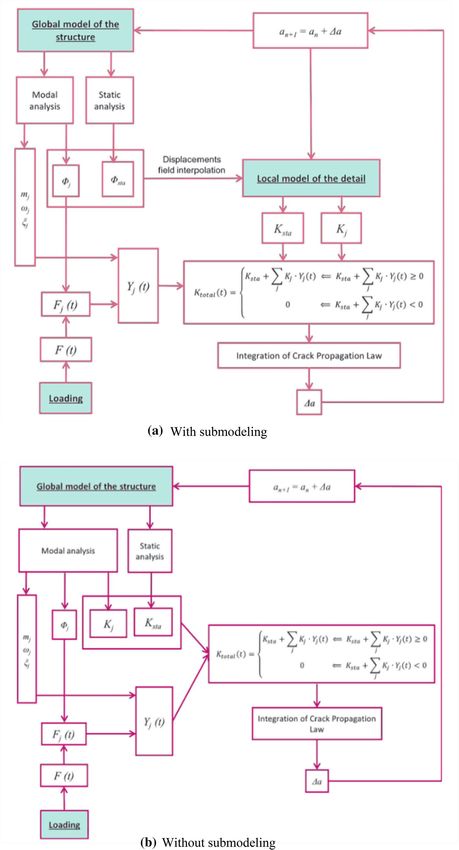
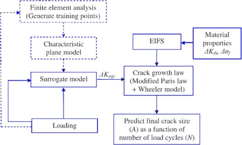
et al. [63, 152] developed an efficient crack analysis using Evaluation of crack in the thermal environment is vastly
modal stress intensity factor and their research methodology studied. Han and wang [156] investigated the thermal shock
flowchart is shown in Fig. 8. The total stress intensity factor resistance of multiple cracking in functional graded mate-
for dynamic loading is given in Eq. (22): rial (FGM). Thermal shock resistance was determined based
Ktotal = Ksta + Kdyn on the stress-based and fracture mechanics-based criteria.
(22)
Zhang et al. [153] also examined the thermal shock resist-
ance of FGM in a mixed-mode crack. The modelled con-
√
where Ksta (t) = Cn a. sta
√ sidered both strength and fracture theories pondering the
Kdyn (t) = Cn a. dyn failure criteria of maximum local tensile stress, maximum
thermal stress intensity and maximum hoops stress criterion.
The total value of K through time is expressed as The transient temperature field for finite element equation is
expressed in Eq. (26).
⎧ K + ∑ K .Y (t) ifK + ∑ K .Y (t) ≥ 0
⎪ sta j j sta j j
j
∑
j
[ ] [ ] [ ]{ }
Ktotal (t) = ⎨ (23) K1 + K2 {T(x, y, t)} + K3 T(x, ̇ y, t) = {P(x, y, t)}
⎪0 ifKsta + Kj .Yj (t) ≤ 0
(26)
⎩ j
where K1 is the heat [ ]conduction matrix, K2 is the con-
[ ] [ ]
Kabayashi and Ramulu [131] evaluated DSIF for unsym- vection matrix and K3 is the heat capacity matrix. Petrova
metrical dynamic. Rokach and Łabędzki [128] proposed the and Schmauder [148] developed a mathematical modelling
method to determine the dynamic stress intensity factor for and evaluated the TSIF of FGM for an interface crack. The
a four-point bend impact test. Wang et al. [129] established parametric analysis showed the dependence of the TSIF at
a dynamic stress intensity factor applying the interaction the crack tip location and its orientation. Stress intensity
integral method. The integral method was executed with- factor under thermal stress was analysed for the interfacial
out crack tip enrichment for both homogeneous and non- crack of bimaterial [42, 121, 135]. The transient SIFs are
homogeneous material. The relationship between interaction observed to be a greater value than in the transient state.
integral and stress intensity factor is given in equation below Nemat and Noda [135] analysed TSIF for functionally gra-
[129, 153, 154]: dient material. They observed that TSIF decreased dramati-
cally for selected nonhomogeneous parameters. Transient
2 ( aux
+ KII KIIaux
)
I= ∗ KI KI (24) thermal stress intensity factor was investigated for a hollow
Etip
cylinder with a circumferential crack [141, 142]. Xue et al.
[141] evaluated based on the heat conduction model. It was
13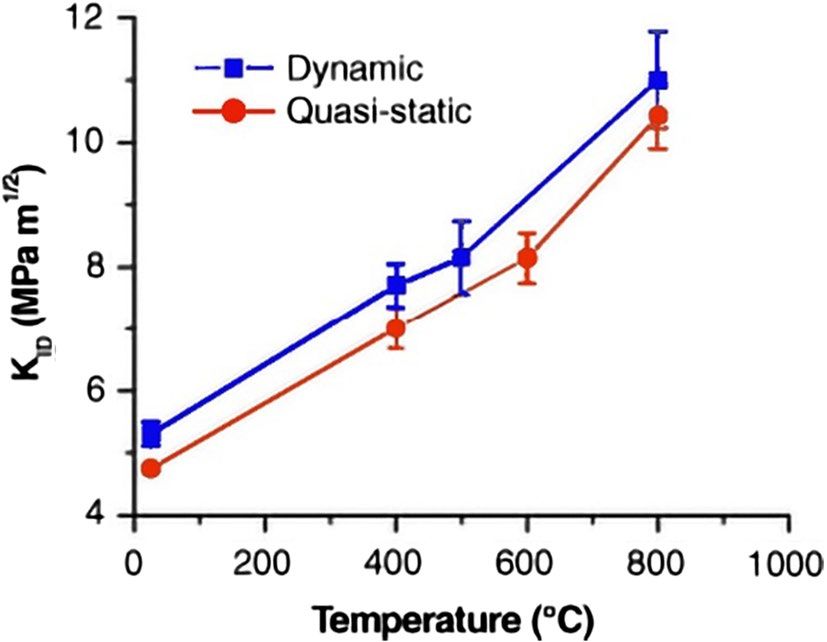
77 Page 10 of 20 Journal of the Brazilian Society of Mechanical Sciences and Engineering (2021) 43:77

Fig. 8 Flowchart for the
application of the proposed
methodology [63]

13
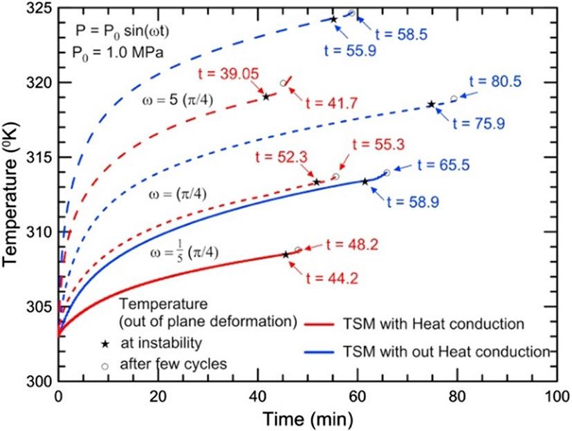
Journal of the Brazilian Society of Mechanical Sciences and Engineering (2021) 43:77 Page 11 of 20 77

found that the thermal stress at the crack tip was different for thermomechanical loading in DSIF was much lower than
different parameter values. Zhang and Li [142] studied the the material gradation. Moreover, DSIF is dependent on the
generalized fractional heat conduction and found a striking crack angle and orientation with correspond to the material
difference in thermal stress intensity factor with the Fourier gradation. Lee et al. [166] and Zhang et al. [167] similarly
heat conduction model. analysed the exponential gradation of FGM to develop the
 Different approaches were used for calculating the thermomechanical stress and displacement.
thermal stress intensity factor for a cracked cylinder [123, Nicholas et al. [168] estimated the crack propagation as
137, 143, 145, 146]. Zhong and Huang [134] observed that the function of the phase angle between load and tempera-
TSIF was not only dependent on applied thermal loading ture. Their research acknowledged the contribution of load
but also dependent on mechanical loading and physical position and time effects. John et al. [169] experimentally
properties of the crack interior. Tanigawa and Komat- worked out TSIF generated by temperature gradient around
subara [140] evaluated the thermal stress of a rectangu- the crack and hence confirmed the thermal load induces
lar plate. Fracture behaviour of the crack was examined crack growth. Park et al. [170] in a similar way categorized
with a non-uniform heat source. Their studied explained the thermal fatigue of an underfill cracking by applying the
the variation in stress intensity depending on the kind of thermal stress and calculated the TSIF using the crack length
parameters like mechanical boundary conditions, thick- correlated to life cycles. Kim and Stone [171] studied the
ness of the plate, orientation of the crack, surface friction, utility of integral parameters for crack propagation under
etc. Lee et al. [138, 147] studied the TSIF for interface thermomechanical loading. Their research reported that the
crack under uniform heat flow. The finding showed the parameters are path-independent for deformation. Chu et al.
stress intensity factor was strongly dependent on material [172] examined the dynamic crack path in a brittle material.
properties. Analysis of thermal stress intensity factor was The aim of their studied was to evaluate the transient heat
also studied using different methods and approaches [122, transfer, dynamic stress evolution under thermomechani-
139, 157, 158]. Assessment of mixed-mode stress intensity cal couple load. Their experiment in disk specimen showed
factor under the thermal and mechanical loading [159]. that the crack branching is within the large heating radius;
 Le and Gardin [160] used the analytical approach however, it goes outside the heating area in case of smaller
based on stress intensity factor and weight function to radius. Maletta et al. [173] analysed the crack-tip thermal
study the crack shape and kinetics of crack propagation and mechanical hysteresis. They tested shape memory alloys
under the thermal cyclic loadings. The result showed the subjected to fatigue loads. Using infrared thermography,
crack decelerated at the deepest point and accelerated at they reported a sudden rise in surface temperature at the
the surface due to the compression state in the centre and initial stage. The SIF versus load curves appeared a nonlin-
tension near the surface. Sankraraman et al. [161] exam- ear hysteretic behaviour reflecting the complex stress–strain
ined the influence of an initial flaw size of the crack. The hysteretic behaviour of SMAs. Merhy et al. [174] studied
stress intensity factor expressed in terms of the initial flaw the crack growth characterization of aluminium alloy. The
size of crack and loadings. The size of the crack opening contribution of parameters like temperature, frequency and
was, however, dependent on the geometry [162]. Another SIF on crack growth was analysed. Crack growth increased
type of crack is a breathing-fatigue crack as discussed by at high temperature with a load ratio on decreasing frequen-
Yan et al. [163]. The researcher proposed the procedure to cies. Temperature effect on crack growth was found depend-
identify the prevailing breathing crack and computed the ent on the applied frequencies.
crack quantitatively.
 Crack is also analysed in different schemes. Huan Chen
[164] considered partially insulated crack. Using the 6 Challenge‑5: stochastic response
hyperbolic heat conduction theory as per Eq. (27), thermal of the structure under thermomechanical
stresses and thermal effect on the crack were examined. environment
 They expressed that the conduction parameters, thermal
conductivity and geometry size have a greater influence on A structure exposed to cyclic loads for a reasonable time
the stress of the crack surface and temperature gradient. may change its global temperature. The changes in tempera-
 ture impact the amount of stress moderation which in turn
 T 2 T alters the deformation of the structures. Khan et al. [175]
a ⋅ ∇2 T = + 2 (27)
 t t studied the outcomes of heat generation in viscoelastic
where a is thermal diffusivity and ∇2 is Laplace differential material under cyclic loading. The cyclic mechanical load-
operator. Ekhlakov et al. [165] presented thermoelastic crack ing was applied in a polymeric beam with or without heat
analysis in FGM. They observed that the influence of the conduction. They found that the higher stress point produces
 more heat which hastened the stress relaxation and triggered

 13
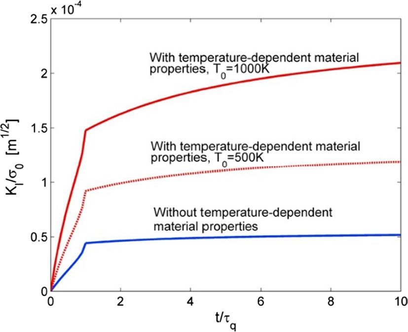
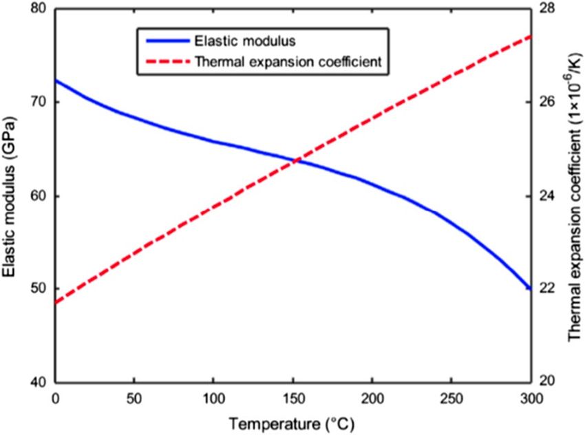
77 Page 12 of 20 Journal of the Brazilian Society of Mechanical Sciences and Engineering (2021) 43:77

thermal gradient in the polymer beam. In the case of the heat
conduction, a uniform temperature preceded to the insta-
bility of the beam by diminishing the overall stiffness as
shown in Fig. 9. El-Kafrawy [176] and Bovsunovsky and
Surace [177] confirmed that the presence of a crack in beam
or frame reduces the dynamic response. Hasbroucq et al.
[178] studied the elastic–plastic response under the thermo-
mechanical loading where the elastic properties vary with
the temperature. The result showed that the residual stress
and strain fields were time-dependent. Kidane and Shukla
[179] experimentally investigated the dynamic behaviour
of Ti/TiB functionally graded material exposed to ther-
momechanical loading. The effect of the temperature on
 Fig. 10 True stress–strain curve as a function of time of Ti/TiB FGM
dynamic response was studied by infrared spot heaters. The [179]
stress–strain curve at a different temperature is illustrated in
Fig. 10. At high temperature, the materials displayed thermal
relaxing and caused a reduction in compressive strength and Ebrahimi et al. [185] analysed the thermal effect on vibra-
increase in failure strain. tion behaviour of functionally graded beams with porosities.
 Thermal effect on vibrating structure has been widely The influence of porosity volume fraction, material profile,
investigated [12, 18, 25, 32, 61, 180–186]. Cao et al. [181] temperature and boundary condition on frequencies was
investigated numerically the thermal vibration and thermal examined. The increase in porosity fraction increased the
contraction of single-wall carbon nanotubes (CNT). They dimensionless frequencies. But at elevated temperatures, the
explained that the effect of thermal vibration is more distinct increase in gradient index value decreased the frequency.
than quasi-static thermal expansion which causes the ther- The natural frequencies decreased with an increase in tem-
mal contraction in both the radial and axial directions when perature and moving to zero at critical temperature. How-
the temperature is well below 800 K. Zhang et al. [184] ever, the frequencies increased afterward.
also investigated the thermal effect on the beam. Their work In another paper, Ebrahimi and Salari [186] studied
focuses on the high-frequency response in thermal expo- the vibration behaviour of functional graded (FG) nano-
sure using the energy flow analysis method. The study high- beams under the effects of in-plane thermal loading. The
lighted the increase in vibration response of the beam with parametric study showed that change in temperature, mode
the increase in temperature. In supplement, two temperature- shape and boundary conditions influenced the fundamental
dependent material properties, elastic modulus and thermal frequencies. Liu et al. [187] investigated on temperature-
expansion coefficient were considered to verify the thermal dependent of material properties. They focused on ther-
effect as shown in Fig. 11. mal shock fracture in the principle of non-Fourier heat

Fig. 9 Temperature increase at point 1 of the simply supported at
1.0 MPa with/without heat conduction at different frequencies of Fig. 11 Temperature-dependent material properties for aluminium
HDPE polymer [175] alloy [184]

13
Journal of the Brazilian Society of Mechanical Sciences and Engineering (2021) 43:77 Page 13 of 20 77

conduction. The thermal stress intensity factor was found 7 Conclusion
to be vastly receptive to the temperature-dependent mate-
rial properties. This review emphasizes the existing research complexities
 The variations of TSIF with shock time are presented in the area of fatigue and fracture modelling. Assessing
in Fig. 12. Cui and Hu [180] studied on Euler–Bernoulli fatigue damage accurately under vibration-based loads
beam under uniform heating. They observed that there is still a challenge. Most of the available researches on
is a small influence of temperature-dependent material thermomechanical vibrations are more or less focused
properties on the natural frequency at low temperature on application-based studies. Researchers apply differ-
but developed greater influence at high temperature. Faz- ent theories to evaluate the characteristic of the com-
zolari [188] also analysed the modal characteristic of plex geometry. However, modelling of thermomechani-
FG with temperature-dependent materials under thermal cal vibrations become multifaceted when the geometry
loading. They analysed the use of the higher-order equiva- is complicated. Thus, the available research data for the
lent single-plate theories to study the two-volume frac- fatigue damage assessment are still lacking of analytical
tions: power-law function (P-FGM) and sigmoid function reasoning and proper explanations concerning accurate
(S-FGM). The declining rate of dimensionless frequency fatigue measurement.
of temperature-dependent FGM was found to be more than Complications in fatigue and fracture life estimation
temperature-independent FGM at elevated temperatures. are another challenging obligation. The difficulties of
Silva et al. [189] performed the modal analysis at elevated fatigue life estimation are due to the inhibiting variables.
temperatures. They studied the effect of non-uniform Fatigue life is dependent on the loading histories, loading
temperature distribution heated rectangular plate. The sequences, loading amplitude and frequency, operation
resonant frequency and displacement data were extracted environment, physical properties, etc. Different materials
by the pulse laser-digital image correlation method. The correspond to different fatigue life patterns allowing exist-
resonant frequencies were noticed to be higher in trans- ing life estimation methods inadequate. A number of meth-
verse heating while longitudinal heating did not have much ods and techniques are available to predict the fatigue life.
effect. Finite element analysis suggested the results were Nevertheless, the challenges are the precise measurement
an after-effect of the disparity in the curvature of the plate considering those variables which change independently
at elevated temperature in a steady state. In related stud- according to the working conditions.
ies, Kawamura et al. [190] performed numerical studies Crack propagation is not a new topic but still requires
on nonhomogeneous material properties of a rectangular a comprehensive research to describe its governing math-
plate subjected to a varying temperature at one surface ematics with experimental justifications. Crack growth
and other at zero temperature change. They observed the behaves in a pseudo-manner, especially in thermal con-
amplitude of deflection decreased with the decrease in dition. Many investigations have been complied about
young modulus. the nature of crack growth but fail to conclude with valid
 explanations. Some references, presented in this paper,
 were crack growth rate for supper alloys increases with the
 increase in temperature. Yet, there is no convincing reason
 why and how the crack will behave for different working
 conditions. It is learnt that fracture mechanics parameters
 correlated the crack behaviour at different temperature. In
 theory, crack growth and fracture behaviour at elevated
 temperature is still to address.
 The thermal effect on dynamic response of structure
 has great concern in engineering applications. Structure
 expose to reasonable high temperatures can modify the
 material properties and increase crack propagation. This
 modification influences the overall deformation of the
 structure. The changes in temperature impact the amount
 of stress concentration thereby diminishing the global
 stiffness. Several studies were presented for structural
 vibration in above review. Moreover, thermomechanical
 vibration of structure relating to crack propagation and
 modal properties are still inadequate. It is well known that
Fig. 12 TSIF for the surface crack of depth d/l = 1 [187]

 13
77 Page 14 of 20 Journal of the Brazilian Society of Mechanical Sciences and Engineering (2021) 43:77

the presence of crack reduces the dynamics response of need to obtain permission directly from the copyright holder. To view a
structure. The existing studies are yet to input sufficient copy of this licence, visit http://creativecommons.org/licenses/by/4.0/.
explanations about the dynamic behaviour of structure
under distributed temperature across the structure. The
structural stiffness can be influenced by material micro-
structure, temperature distribution and time of exposure.
 References
Different temperature can cause significant variations 1. Antolovich SD, Saxena A, Gerberich WW (2018) Fracture
in the material properties. Existing studies are limited mechanics—an interpretive technical history. Mech Res Commun
with respect to temperature change and compel exten- 91:46–86. https://doi.org/10.1016/j.mechrescom.2018.03.003
sive investigation in crack and uncrack conditions. The 2. Baxevanis T, Lagoudas DC (2015) Fracture mechanics of shape
 memory alloys: review and perspectives. Int J Fract 191:191–
impact of thermal properties on structural response under 213. https://doi.org/10.1007/s10704-015-9999-z
varying temperatures needs to be investigated. Tempera- 3. Habtour E, Connon WS, Pohland MF et al (2014) Review of
ture-dependent properties like elastic modulus, thermal response and damage of linear and nonlinear systems under
expansion and thermal conductivity changes with respect multiaxial vibration. Shock Vib 2014:1–21. https ://doi.
 org/10.1155/2014/294271
to temperature. The relationship of temperature-dependent 4. Sunder R, Daniewicz SR, Dean SW (2012) Unraveling the sci-
properties with structural response in crack and uncrack ence of variable amplitude fatigue. J ASTM Int 9:1–32. https
conditions has not been established yet. There could be ://doi.org/10.1520/JAI103940
considerable changes in structural response due to vary in 5. Zai BA, Khan M, Khan KA et al (2019) The role of dynamic
 response parameters in damage prediction. Proc Inst Mech
temperature-dependent properties. Dissimilar temperature Eng Part C J Mech Eng Sci 233:4620–4636. https ://doi.
distributions across the structure may also have diverse org/10.1177/0954406219841083
dynamic response trend. Subsequently, the modal prop- 6. Yang L, Fatemi A (1998) Cumulative fatigue damage mecha-
erties will change corresponding to the changes in the nisms and quantifying parameters: a literature review. J Test
 Eval 26:89–100. https://doi.org/10.1520/JTE11978J
temperature. 7. McClung RC (2007) A literature survey on the stability
 Nevertheless, a focus on developing accurate fatigue and significance of residual stresses during fatigue. Fatigue
models, especially for complex geometries, is required in Fract Eng Mater Struct 30:173–205. https ://doi.org/10.111
future. There are many factors still to be considered in mod- 1/j.1460-2695.2007.01102.x
 8. Narasimha M, Kuttan A, Kadoli R (2010) Thermally induced
elling like overloading and geometrical discontinuities. The vibration of a simply supported beam using finite element
existing theories of fatigue and fracture also address with- method. Int J Eng Sci Technol 2:7874–7879
out a proper consideration of temperature effect on struc- 9. Larizza P (2015) Measurement, testing, and diagnosis for
tural dynamics. The change in temperature has impacted micro-manufacturing systems. In: Qin Y (ed) Micromanufac-
 turing engineering and technology. Elsevier, Amsterdam, pp
the mechanical properties which can relate to uncertain 675–704
dynamics responses. Therefore, fatigue and fracture model- 10. Ebrahimi F, Jafari A (2018) A four-variable refined shear-
ling under those criteria will be a good contribution in the deformation beam theory for thermo-mechanical vibra-
existing academic literature. tion analysis of temperature-dependent FGM beams with
 porosities. Mech Adv Mater Struct 25:212–224. https ://doi.
 org/10.1080/15376494.2016.1255820
 11. Ebrahimi F, Salari E (2015) Thermo-mechanical vibration
Funding The author(s) received no financial support for the research, analysis of a single-walled carbon nanotube embedded in
authorship and/or publication of this article. an elastic medium based on higher-order shear deformation
 beam theory. J Mech Sci Technol 29:3797–3803. https://doi.
Compliance with ethical standards org/10.1007/s12206-015-0826-2
 12. Ebrahimi F, Farazmandnia N (2017) Thermo-mechanical
 vibration analysis of sandwich beams with functionally graded
Conflict of interests The author(s) declared no potential conflicts of
 carbon nanotube-reinforced composite face sheets based on
interest with respect to the research, authorship and/or publication of
 a higher-order shear deformation beam theory. Mech Adv
this article.
 Mater Struct 24:820–829. https ://doi.org/10.1080/15376
 494.2016.1196786
Open Access This article is licensed under a Creative Commons Attri- 13. Ebrahimi F, Barati MR (2018) Vibration analysis of parabolic
bution 4.0 International License, which permits use, sharing, adapta- shear-deformable piezoelectrically actuated nanoscale beams
tion, distribution and reproduction in any medium or format, as long incorporating thermal effects. Mech Adv Mater Struct 25:917–
as you give appropriate credit to the original author(s) and the source, 929. https://doi.org/10.1080/15376494.2017.1323141
provide a link to the Creative Commons licence, and indicate if changes 14. Ebrahimi F, Barati MR, Zenkour AM (2018) A new nonlocal
were made. The images or other third party material in this article are elasticity theory with graded nonlocality for thermo-mechanical
included in the article’s Creative Commons licence, unless indicated vibration of FG nanobeams via a nonlocal third-order shear
otherwise in a credit line to the material. If material is not included in deformation theory. Mech Adv Mater Struct 25:512–522. https
the article’s Creative Commons licence and your intended use is not ://doi.org/10.1080/15376494.2017.1285458
permitted by statutory regulation or exceeds the permitted use, you will 15. Hosseini SAH, Rahmani O (2016) Thermomechanical vibra-
 tion of curved functionally graded nanobeam based on

13
You can also read