DEVELOPMENT OF REFURBISHMENT FACILITY FOR REPAIR AND MAINTENANCE OF HIGH PURITY GERMANIUM DETECTORS - BARC/2021/E/015 B - International Nuclear ...
←
→
Page content transcription
If your browser does not render page correctly, please read the page content below
BARC/2021/E/015

                                                             BARC/2021/E/015
DEVELOPMENT OF REFURBISHMENT FACILITY FOR
  REPAIR AND MAINTENANCE OF HIGH PURITY
          GERMANIUM DETECTORS
                         by
        Nilesh Tawade and Suparna Sodaye
               Radiochemistry Division
              Chandra Shekhar Datrik
            Product Development Division

                    2021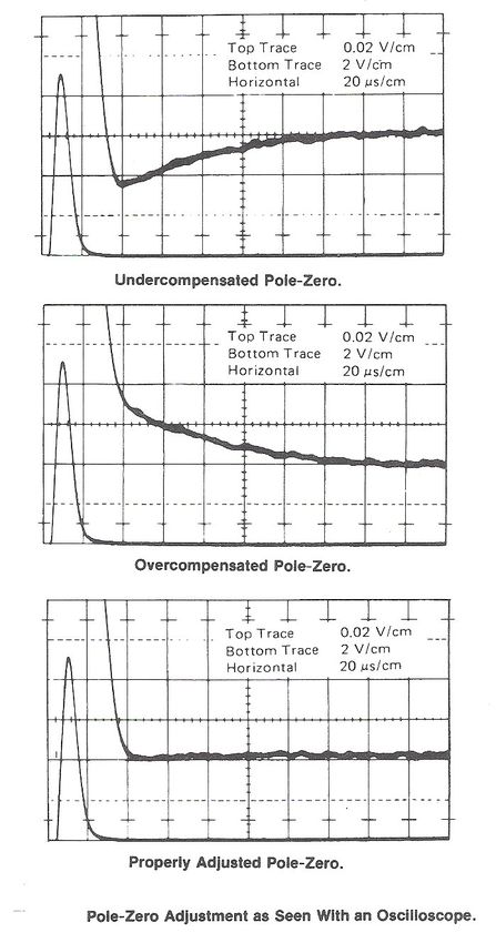
BARC/2021/E/015
BARC/2021/E/015

                              GOVERNMENT OF INDIA
                          DEPARTMENT OF ATOMIC ENERGY

                  DEVELOPMENT OF REFURBISHMENT FACILITY FOR
                    REPAIR AND MAINTENANCE OF HIGH PURITY
                            GERMANIUM DETECTORS
                                           by
                         Nilesh Tawade* and Suparna Sodaye
                                nstawade@barc.gov.in*
                                 Radiochemistry Division
                               Chandra Shekhar Datrik
                              Product Development Division

                       BHABHA ATOMIC RESEARCH CENTRE
                               MUMBAI, INDIA
                                    2021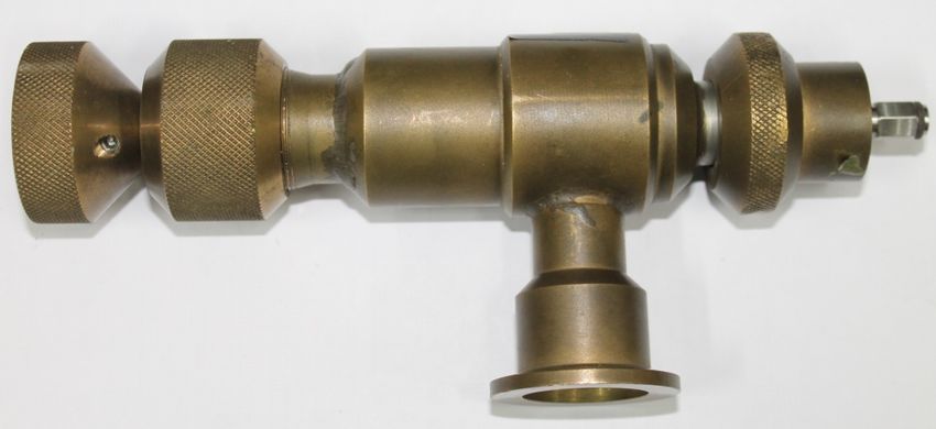
BARC/2021/E/015

              BIBLIOGRAPHIC DESCRIPTION SHEET FOR TECHNICAL REPORT
                                (as per IS : 9400 - 1980)

01   Security classification :    Unclassified

02   Distribution :               External

03   Report status :              New

04   Series :                     BARC External

05   Report type :                Technical Report

06   Report No. :                 BARC/2021/E/015

07   Part No. or Volume No. :

08   Contract No. :

10   Title and subtitle :         Development of refurbishment facility for repair and maintenance of
                                  High Purity Germanium Detectors

11   Collation :                  27 p., 14 figs.

13   Project No. :

20   Personal author(s) :         1. Nilesh Tawade; Suparna Sodaye
                                  2. Chandra Shekhar Datrik

21   Affiliation of author(s) :   1. Radiochemistry Division,
                                  2.Product Development Division
                                  Bhabha Atomic Research Centre, Mumbai

22   Corporate author(s) :        Bhabha Atomic Research Centre, Mumbai - 400 085

23   Originating unit :           Radiochemistry Division,
                                  Bhabha Atomic Research Centre, Mumbai

24   Sponsor(s) Name :            Department of Atomic Energy

     Type :                       Government

                                                                                        Contd...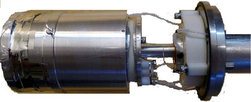
BARC/2021/E/015

30   Date of submission :               July 2021

31   Publication/Issue date :           August 2021

40   Publisher/Distributor :            Head, Scientific Information Resource Division,
                                        Bhabha Atomic Research Centre, Mumbai

42   Form of distribution :              Hard copy

50   Language of text :                  English

51   Language of summary :              English

52   No. of references :                5 refs.

53   Gives data on :
     Abstract : High Purity Germanium (HPGe) detector is a high resolution gamma-ray detector used
60
     to analyze and quantify gamma emitting radioisotopes. It is cooled to liquid nitrogen temperature
     (-77K) to reduce thermal noise, thereby, minimizing the leakage current. Also some of the electronic
     components like FET, feed-back capacitor and resistor are kept in vacuum enclosure near to
     detector to reduce add-on electronic noise and obtain better resolution. This report contains the
     description of the frequent problems encountered during operational breakdown and the strategy
     followed to resolve these problems.

70   Keywords/Descriptors : HIGH-PURITY GE DETECTORS; PERFORMANCE;
     MAINTENANCE; LEAKAGE CURRENT; GAMMA RADIATION

71   INIS Subject Category :            S46

99   Supplementary elements :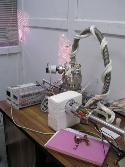
DEVELOPMENT OF REFURBISHMENT FACILITY FOR REPAIR
AND MAINTENANCE OF HIGH PURITY GERMANIUM DETECTORS
           Nilesh Tawade1*, Chandra Shekhar Datrik2 and Suparna Sodaye1
              1
               Radiochemistry Division and 2Product Development Division
                           Radiochemistry & Isotope Group
            Bhabha Atomic Research Centre, Trombay, Mumbai-400085, India
                                  nstawade@barc.gov.in*

Abstract

High Purity Germanium (HPGe) detector is a high resolution gamma-ray detector used to
analyze and quantify gamma emitting radioisotopes. It is cooled to liquid nitrogen
temperature (-77K) to reduce thermal noise, thereby, minimizing the leakage current. Also
some of the electronic components like FET, feed-back capacitor and resistor are kept in
vacuum enclosure near to detector to reduce add-on electronic noise and obtain better
resolution. This report contains the description of the frequent problems encountered
during operational breakdown and the strategy followed to resolve these problems.

Keywords: HPGe Detector, cool FET, Charge sensitive preamplifier
CONTENT
1.        INTRODUCTION ...................................................................................................         1
2.        MAJOR MAINTENANCE IN THE PAST ............................................................                               1
2.1.      Poor Resolution and Peak Shift Problem ................................................................                  1
2.2.      Feed through Related Problem ................................................................................            2
2.3.      Preamplifier Related Problems ...............................................................................            3
2.3.1. Leakage Current Indicator LED Continuously ON ................................................                              3
2.3.2. DC Shift in Preamplifier Output .............................................................................               5
2.4.      High Voltage Related Problems ..............................................................................             6
2.4.1. Detector Not Accepting High Voltage ……………………………………………… ....                                                                 6
2.5.      Poor Resolution Problems …………………………………………………….......                                                                     7
2.5.1. Improper Pole-Zero Adjustment …………………………………………………..........                                                                 7
2.5.2. Noise Pickup ………………………………………………………………………… ........                                                                          7
2.5.3. Disturbance in the FET Parameters ………………………………………………… ...                                                                   7
2.5.4. Moisture Deposition on Preamplifier Board ……………………………………… .....                                                             8
2.5.5. Insufficient Cooling To the Electronics ……………………………………… .............                                                       8
2.5.6. Instability in Electronics Modules or Components ……………………….................                                                 8
2.6.      Cool FET Problem ………………………………………………………… ..........                                                                       8
2.6.1. Cause of FET Failure ………………………………………………………………… ....                                                                         8
2.6.2. Identification of FET Failure Problem and Its Replacement …………………… .....                                                    9
2.6.3. FET Replacement ……………………………………………………………………… ....                                                                            9
2.7.      Detector Cooling Problems ………………………………………………… .........                                                                  9
2.7.1. Vacuum Leak in Detector Enclosure ……………………………………………… ......                                                                10
2.7.2. Liquid N2 Filling Problem in Dewar of HPGe Detector ………………………… .....                                                       10
2.7.3. High Liquid Nitrogen Evaporation Rate .................................................................                    11
3.        CONCLUSION ........................................................................................................     11
ACKNOWLEDGEMENT ...................................................................................................               11
REFERENCES ....................................................................................................................   12
List of Figures
Fig. No. Title Page
Fig.1 HPGe Detector based Gamma Radiation Detection System 13
HPGe Detector based Gamma Radiation Detection System with 13
Fig.2 modules
Moisture condensation over detector enclosure and electrical feed 14
Fig.3 through during shutdown
Fig.4 Preamplifier output signal 14
Fig.5 The electrical feed through replacement 14
Graph of Leakage current and detector capacitance V/s applied
Fig.6 voltage 15
Fig.7 Transverse section of HPGe Detector 15
Fig.8 Picture of feedback components register and capacitor 16
Fig.9 Picture of High Voltage filter modules 16
Fig.10 Pole Zero adjustment process 17
Fig.11 Picture of preamplifier cable 18
Fig.12 Turbo molecular based high vacuum HPGe Detector evacuating
System 18
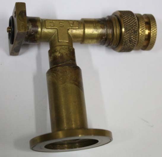
Fig.13 Photograph of different vacuum port used for Detector evacuation 19
Fig.14 Internal part of HPGe detector kept in vacuum 20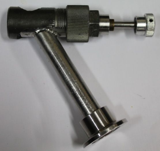
1. INTRODUCTION
A High Purity Germanium (HPGe) detector is a high resolution gamma-ray detector, used for
the measurement of energy of the gamma-ray emitted by a radioisotope. This information is
useful in qualitative and quantitative estimation of any gamma-ray emitting radioisotope. A
typical HPGe detector (crystal size ~2” dia x 2” thickness) has a resolution of the order of
2.0 keV at 1332 keV gamma-ray energy of 60Co.

In order to obtain such a good resolution, the detector crystal is grown from high purity
Germanium having the intrinsic impurity concentration < 1010 atoms/cc of either p-type or
n-type. The p-n junction is created by implanting electrical contact with appropriate electron-
rich (n+) Lithium diffused contact and hole-rich (p+) Boron ions implanted contact on p-type
or n-type crystal, respectively[1]. The detector crystal is placed in an ultra-high vacuum
chamber (~10-7 torr) with an end cap made of Beryllium, carbon or aluminum, as per the
application. The crystal is cooled to liquid nitrogen temperature (77 K) and operated at high
voltages (~ in kilo Volts) for obtaining carrier free depletion region in the desired volume of
the crystal and efficient collection of charges, which are produced due to gamma radiation
interaction in this region.

Also, this system required a cool FET (Field Effect Transistor) based good quality charge
sensitive preamplifier, Spectroscopy amplifier and Multichannel Analyser for obtaining well
resolved gamma-ray energy spectrum. The block diagram of HPGe detector based gamma
energy spectrometry system is shown in (Fig.1) and (Fig.2) gives a modular diagram of
different components of the HPGe based gamma-spectrometry systems. It is clear from this
figure that the temperature sensor and the FET are placed inside the vacuum chamber along
with the crystal. The preamplifier and the HV filter are also placed very close to the detector,
just outside the vacuum chamber. It’s a very delicate and expensive system and often
encounters problems due to various reasons resulting in poor performance.

2. MAJOR MAINTENANCE IN THE PAST
The HPGe system requires proper ventilation and sufficient cooling in the laboratory with
controlled humidity in air for effective operation of the electronics components. The
temperature and humidity levels of our laboratories are generally controlled and maintained
during operation. However, during ventilation shutdown (planned or unplanned), the
humidity and temperature controls are lost. So, a practice of switching off the HPGe detectors
is followed to avoid problems due to power surge and excess humidity. Listed below are a
few major issues that were encountered more frequently and attended:

2.1. Poor Resolution and Peak Shift Problem
Frequently, it has been seen that when the system is switched ON after such shut downs, the
detector shows poor resolution or a peak shift. One reason for such a behavior is attributed to
the condensation of moisture at the feed through points of High Voltage and preamplifier and
forming small droplets (Fig.3). The droplets, being a good conductor of electricity creates
High Voltage insulation breakdown at the feed through. This phenomenon creates hurdle in
the proper supply of High Voltage to the detector and produced fluctuations in the applied

                                                                                              1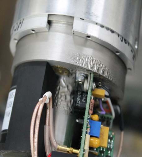
bias voltage to the detector. The minor fluctuations are filtered out by High Voltage filter
circuit. But such frequent fluctuation in the detector bias may lead to deteriorate the FET
function and in future may damage it.

Hence, before restarting the HPGe detector after a ventilation shutdown, the following
procedure was developed. The moisture condensation on the detector body was wiped with a
piece of clean and soft cloth or tissue paper. Then, the preamplifier box was opened gently
and the water droplets were removed with soft moisture-absorbing tissue-paper. Dry air or
little warm air was flushed over the preamplifier board and feed through junction points using
hand held hair dryer. It was suggested not to use hot air (Hot air flow may create vacuum
leaks at feed through junctions and may spoil the vacuum level). The preamplifier boxes was
reassembled and only preamplifier power was applied for 10 to 15 minutes to check the
stability of DC level of preamplifier output signal using an oscilloscope. The stable DC
voltage level with 100 mV (peak to peak) noise band and no DC voltage shift (Fig.4a)
confirmed the removal of moisture from the preamplifier board. The HV was then applied to
the detector with monitoring DC output voltage signal of preamplifier. The signal should
show proper swing (upward/downward, depending upon the applied polarity of High
Voltage) and immediately come back to ground level. The few hundred Volts of High
Voltage was applied to detector for one hour so that moisture gets completely evaporated
with proper flow of electrical signal. After ensuring proper stability of system, complete
recommended bias was applied to the detector. The shape of preamplifier output signals
before applying High Voltage and after applying High Voltage are shown in (Fig.4(a-b)).

If moisture problem persists during every ventilation shutdown, then instead of making
complete system off, if possible few hundred volts (200 V to 300 V) bias is to be applied to
the detector during ventilation shutdown period. This will refrain the moisture from
depositing over the preamplifier and feed through points.

2.2. Feed Through Related Problem
Generally the HPGe detector has two feed through. One of them is used to couple the
component (in vacuum) like FET and charge sensitive loop with the preamplifier board
(which is at room temperature) while other is used to connect High Voltage to the detector
through High Voltage filter modules. The feed-through used in Ortec make HPGe detector
has four pins, with smooth surface and has socket type connector to establish a connection
with Preamplifier (PA) board. So, no corrosion or bad contact is developed on the feed
through and it is easy to carry out disconnection and re-connection of the feed through with
the PA board. In other detectors like Bruker Baltic, DSG, Gamma PGT and Canberra Eurysis
make, the feed through are of poor quality and preamplifier board connecting wires are
directly soldered at the feed through junctions. With time, the junctions get corroded due to
air and moisture resulting in the formation of green color layers. This creates bad contacts on
the feed through. The pins are very delicate and fragile. So, extra care is to be taken during
removing and reconnecting the wires with proper labeling. Two feed though related problems
are explain below

2
a. In one of DSG make HPGe detector, an oxidized layer was formed on the preamplifier
feed through pins due to excessive humidity. It was generating bad contacts. Also the
corrosion was very deep and had almost spoiled the detector feed through (Fig.5). Few of
the pins had broken at the base. So, a fresh feed through was obtained from the supplier
along with glue. The vacuum was leak to do replacement of the feed through. The each
contact of pins of feed through was soldered and proper contacts were established. The
preamplifier circuit was reassembled and the preamplifier circuit connection was test with
test input pulse. The detector was re-evacuated to ~ 10-6 mbar vacuum level. The detector
was tested with standard Eu152 source and found to be restored to working condition.
b. Similarly in other Eurysis HPGe detector, an oxidized layer was formed on the feed
through pins due to excessive humidity. It was generating bad contacts. This was a very
delicate and challenging job as the pins were very delicate. The bad contacts on the pins
were removed gently and the pins socket was cleaned with rust remover. The preamplifier
circuit was reassembled.
2.3. Preamplifier Related Problems
The preamplifier circuit of HPGe detector has charge integrator followed by differentiator
and amplifier. The output of the preamplifier is a tail pulse having 50 nsec rise time and 100
µsec fall time. Before applying bias to the detector the preamplifier output noise should be
less than 200 mV peak to peak. During application of bias, the noise level should decrease
gradually. At recommended bias it should be less than 50 mV (Fig.4b).
2.3.1. Leakage Current Indicator LED Continuously ON
For any DC-coupled charge-sensitive preamplifier, if the energy rate (count rate × energy
product) exceeds a given level (value dependent on the particular system), the preamplifier
will shut off. As the energy rate approaches this level, the detector system may suffer from
excessive resolution degradation and peak shift. If the energy rate hovers around the shutoff
level, the preamplifier may turn on and off intermittently. Obviously, data collected under
such conditions are not reliable and corrective action should be taken. A circuit within the
preamplifier monitors the charge loop output voltage. When a condition of excessively high
rate exists, an output is provided suitable for lighting an LED located in the preamplifier
shield [2].
The increase in DC level indicates increase in the surface leakage current and oscillations in
the DC level of preamplifier signal indicates insulation breakdown. The HPGe detector
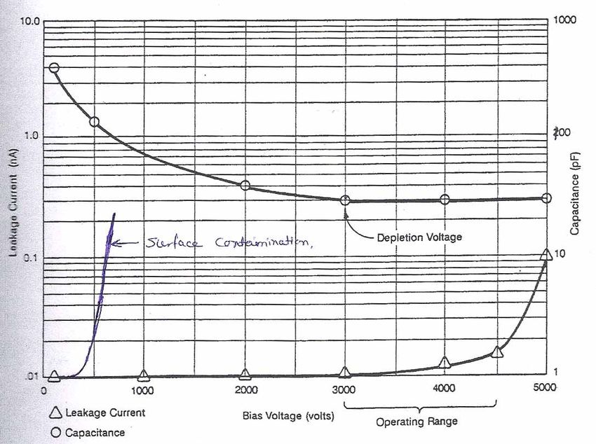
system has a test point outside the preamplifier to measure the leakage current. As per the
specification, it must be less than ± 200 mV. The test point voltage should remain in desired
limits with increase in bias voltage (Fig.6). If this test voltage has increasing nature with
increasing High Voltage the detector has underwent thermal shock and need thermal
recycling. This problem is also indicated by the leakage current indicator, LED diode, remain
continuous ON.
32.3.1.1. Thermal Shock HPGe detector works at LN2 temperature and is continuously kept in vacuum of the order of 10-6 mbar. To improve the vacuum further by removing the residual gases, detector is equipped with molecular sieves (charcoal) at the bottom of the cryostat (Fig.7). It absorbs residual gases around the detector improving the vacuum further. Sometimes, either due to discontinuous supply of LN2 or its high evaporation rate, temperature around the detector starts rising towards room temperature. This will release trapped residual gases in the space around the detector volume inside the enclosure and slightly degrade the vacuum. Meanwhile, if the LN2 is filled even before the detector and the molecular sieve reached to the room temperature, detector starts cooling to liquid nitrogen temperature from the current temperature. Since the molecular sieve is not reactivated to absorb this residual gas, the residual gas remains around the detector surface and create bad vacuum inside the detector enclosure. Sometimes this residual gas may get adsorbed on the detector surface (the surface coated with Germanium oxide to create High Voltage insulation between contacts) and contaminate the detector surface which may produce surface leakage current. Also, at higher voltages, these gas molecules discharge and create high leakage current (Fig.7). This saturates the preamplifier and creates DC shift in the preamplifier output. This action is termed as Thermal Shock to the HPGe Detector. Such situation is indicated by continuous glowing of high count rate indicator [2-4]. The problem is noticed frequently in the portable HPGe detectors. This problem is labeled as bad vacuum. Most of the time ‘Thermal recycling’ may solve this problem but if not then re-evacuation is required to solve the problem. 2.3.1.2. Thermal Recycling The detector is warmed up naturally from liquid nitrogen temperature to room temperature and again cooled to liquid nitrogen temperature. This complete process is called as thermal recycling [3-4]. For this, the detector stick is removed from the Liquid nitrogen container and covered with a clean cloth to absorb water which gets condensed over the stick. The system is then allowed to warm up until it attains room temperature (at least 2 days). It is kept at a safe place to avoid jerks. At room temperature, the detector releases the absorbed residual gases from the detector surface. Also, the molecular sieve gets reactivated. The detector stick is then fixed back in the Dewar. The Dewar is filled with Liquid nitrogen. As the molecular sieve attains low temperature it absorbs the residual gases present around the crystal surface and improves the vacuum [3-4]. In one of the Baltic make HPGe detector, it was not accepting High Voltage above 900 V (recommended bias was 2200 V). Also, the high count rate signal was continuously ON, indicated high DC leakage current. The test point voltage was 2 V above 900 V and increased with applied bias. Thermal recycling did not reduce the leakage current. Then, the detector envelope was evacuated to 3.6 x 10⁻⁶ mbar using a turbo molecular pump. This reduced the leakage current to a desirable level and detector start accepting High Voltage. Many detectors 4
(having similar high leakage problem) of different make were refurbished using
re-evacuation.

2.3.2. DC Shift in Preamplifier Output
The preamplifier output signal should not have any DC shift. If there is any DC shift, it may
be of two types:

   1. Increases with applied bias, which is mostly because of thermal shock as discuss
      earlier.

   2. Fixed DC shift independent of applied bias which is mainly due to failure of the
      preamplifier circuit.

Following probable faults were observed during fixed type of DC shift:

2.3.2.1. DC Shift of ±12 V/±24 V
The preamplifier needs ±12 V and ±24 V low voltages for its proper functioning. If one of the
power supplies fails, it shows DC shift in the preamplifier output signal. The desired power
supplies are connected to preamplifier board through two LC filter circuits present in the
spectroscopy amplifier and preamplifier board itself. The LC filter circuit has Tantalum
polarized Capacitor. Over a time period, this capacitor becomes short. So, huge current flows
through the inductor and it damages the inductor components. Replacing these components
with fresh ones may resolve the problem. But, if it has further spoiled the electronic
components, one has to trace the faulty components.

2.3.2.2. DC Shift of Less Than ±7 V
The preamplifier has two loop, integrator loop and differentiator loop. The preamplifier board
has test input signal through which a test input tail pulse (generated with a test pulse
generator) is applied to the preamplifier board. The signal at the integrator out is monitored
with the DC shift voltage. The shape of the pulse, monitored at integrator output, must be
same as the input pulse with no DC shift. This confirms the fine working of the integrator
loop. Mostly the DC shift is observed due to non-working of this integrator loop. The
integrator loop has fine tuning FET parameter resistor trim pots to adjust the drain voltage
and drain current. The drain voltage and drain current of FET should be 5 V and ~ 15 mA,
respectively, to operate FET in its operating region. All these circuits are monitored closely to
diagnose the problem. But, if the signal at integrator is ok, then the buffer circuit may have
problem. It is a transistor based push pull amplifier or IC based Op-amp buffer circuit.
Mainly, the transistor or IC turns out to be bad over a time period or during any electrical
spikes. Similar components should be used to replace the faulty components to get proper
resolution or replace the preamplifier board with new spare.

One of the HPGe detector (DSG make) was showing 4.5 V DC shift in the Preamplifier
output signal. The test point voltage was 20 V. As per the trouble shooting given in the
manual, preamplifier might be bad. But after replacing a preamplifier part with a new spare,

                                                                                               5
the problem did not get rectified. The test point swung from -3.8 V to +20 V while adjusting the FET operating parameters and was not able to hold 0.0 V. This observation concluded that the feedback resistor (placed in vacuum) might be open. The vacuum was broken with vent valve to test this resistor. Since resistor value was very high (1 to 5G ohm), it was tested by designing an integrator circuit having a ramp of 2 x 10² V/sec (Components: Resistor 5G ohm which was to be tested, Capacitor 0.5 pF, input voltage 0.5 volt). With the bad resistor, which was removed from detector assembly, no ramp was observed. Replacing the faulty resistor (Fig.8) solved the problem. The vacuum cavity was evacuated to 10-6 mbar pressure. The HPGe detector was then tested with ‘Eagle/Classic MCA system’ at positive 4000 Volt operating High Voltage and 8 micro sec shaping time constant. The resolution and FWTM/FWHM ratio were 2.1 keV and 1.88, respectively, at 1332 keV gamma peak. 2.4. High Voltage Related Problems The detector needs High Voltage (for coaxial shape detector, 3 to 5 kilo Volts and for planar detector around 1 kilo volts) to collect hole-electron charge pairs produced due to gamma interaction with the detector. The High Voltage path needs extra protection to avoid insulation break down. The High Voltage is applied to the detector through a filter module which protects the detector during electronic surge current. M/s Ortec make and M/s Canberra Eurysis make detectors has specially designed filter modules (Fig.9). We had procured these special modules during detector procurement as spares. While in-case of M/s Baltic Scientific Instruments and M/s DSG make instruments, the detector has a filter circuit made up of resistor and capacitor network. Some of the High Voltage related problems were reported below. 2.4.1. Detector not Accepting High Voltage This is one of the frequently observed problems in the Canberra -Eurysis make detectors. Generally, when bias is applied to the detector, the momentary shift in DC level is observed on oscilloscope with reduction in noise band. If this is not observed and also the RED LED indicator in not responding in normal way during biasing the detector means detector is not accepting bias. This problem arises due to failure of High Voltage supply module or High Voltage filter module. It can be ruled out by testing High Voltage unit without load. a. In one of the Eurisys make HPGe Detector, it was tested that the preamplifier board of the detector was responding properly to the test input but the detector was not responding to the applied detector bias. Since the bias to the detector was being applied through HV filter module, it was tested and found to be faulty. This module had been replaced with a new one (EFD SP1376A). Then the detector started responding to the applied bias. The system was tested with a PC based compact card (AHV-2pc and 5000 MCArd) consist of inbuilt High Voltage power supply, Low Voltage Power Supply, Spectroscopy Amplifier and ADC. It was tested at 2 µsec shaping time at 4 K ADC gain. The resolution and FWTM/FWHM ratio were measured as 2.05 keV and 1.85 at 1408 keV. 6
b. In one of the Ortec make Coaxial HPGe detectors, water droplets were accumulated in the
   vicinity of the preamplifier circuitry and HV filter module. In this situation, the user
   applied High Voltage to the detector. This had spoiled the HV filter module
   (Model-138EMI). Hence, the detector was not accepting the High Voltage. The faulty
   HV filter was replaced with a spare HV filter and detector was made functioning.

c. In another case, an Ortec make Coaxial HPGe detector was accepting High Voltage but it
   was giving poor resolution with negative spikes in the preamplifier output. The resolution
   of the detector was 5.8 keV at 1332 keV. The preamplifier was checked with a test input
   pulse to test its quality. The preamplifier test point measured value used as an indicator
   for low leakage current. The High voltage path was analyzed and the High Voltage filter
   was found to be faulty. It was replaced with a spare one which had solved the problem of
   negative spikes.

2.5. Poor Resolution Problems
This is one of the most commonly encountered problems of the detector. There are various
factors which are responsible for poor resolution. The poor resolution always disturbs the
gaussian shape and FWTM/HWHM ratio. The detector is said to have good resolution if the
ratio is in between 1.8 to 1.9. Some of the reasons for poor resolution and bad shape are
discussed below:

2.5.1. Improper Pole-Zero Adjustment
If the pole-zero potentiometer (trim pot available at front panel of the Spectroscopy
amplifier) is not properly adjusted, undershooting or overshooting is observed in the
amplifier output, when the signal is observed on oscilloscope (Fig.10). This pole-zero pot
adjustment gets disturbed due to changing of shaping time constant or replacing a
spectroscopy amplifier. This pot is adjusted by observing the signal in an oscilloscope to
remove undershoot or overshoot.

2.5.2. Noise Pickup
The preamplifier and amplifier used in the HPGe detector system are highly sensitive. It
absorbs jerk as well as surrounding noise such as due to motor or ultra-high frequency noise
from neighboring instruments. Also, the detector systems must have a common ground,
means all points of the system must be connected to a common electrical junction box. These
problems can be diagnosed using an oscilloscope where one can see this frequency
interference in the preamplifier and amplifier output signal.

2.5.3. Disturbance in the FET Parameters
When a new component is mounted on the preamplifier board, after removing the faulty
component or the entire preamplifier board is replaced, the FET parameter may get disturbed
and hence, may worsen the detector resolution. So, fine tuning of the FET voltage and current
pot (available on preamplifier boards) can be done to adjust FET parameters, if required.

                                                                                           7
2.5.4. Moisture Deposition on Preamplifier Board The moisture deposition on the preamplifier board may also disturb the peak shape and hence, detector resolution. A sharp noise peak, with high counts, is observed in lower channels with broad peaks in the MCA spectrum. The treatment to this problem is discussed in problems related to moisture. This problem is frequently encountered during the rainy season, when the humidity levels are very high. In Baltic detector, a small vacuum, below atmosphere, is created inside the preamplifier housing to avoid moisture condensation. 2.5.5. Insufficient Cooling to the Electronics Sometimes due to insufficient cooling inside the computer (mainly MCA) or in NIM bin, the electronic components may have deviation from their actual performance. This produces instability in peaks of gamma spectrum and hence, resolution gets affected. To avoid this problem, proper cooling and ventilation inside the computer or the NIM BIN is to be ensured. 2.5.6. Instability in Electronics Modules or Components It was observed that the poor quality components used in the amplifier like the rotary switch or potentiometer may produce bad contacts. This may cause variation in the signal and hence, disturb the shape and resolution. One of Ortec HPGe detector was giving 45 keV resolution at 1332 keV along with peak shift during acquisition. When observed on the oscilloscope, the preamplifier output signal was showing attenuation and bad shape. On further investigation it was found that the hybrid IC (HPA0806) used in the integration circuit of preamplifier was not functioning properly. Then, the entire preamplifier board was replaced with a new spare one. The detector was tested and the resolution was measured 2.2 keV at 1332 keV. 2.6. Cool FET Problem The FET is very specific and essential electronics part of the preamplifier board. There are various miss handling processes, which is responsible for failure of the FET. The user should take care of the following points while handling the detector: 2.6.1. Cause of FET Failure The detector bias is gradually raised by monitoring the intensity of indicator LED (high count rate LED, usually RED coloured). The intensity of color indicates a flow of DC current through the detector during bias application, which also passes through the FET. The excess current may damage the FET gate to channel junction. Hence, sudden ON/OFF of the detector bias should be avoided, which generally happened during a power trip. The mains power should be ALWAYS delivered through a relay board to the detector bin power supply, so that during a power trip (ON/OFF process) sudden High Voltage should not reach the detector. Now a days, the High Voltage unit has an extra protective switch to make it ON. Such High Voltage units are to be used for extra protection. Also, after a power trip, always reduce the High Voltage to zero before switching ON the system. Before applying bias to the detector system, always monitor the detector temperature. The indicator LED (usually Green colored) is there on the detector. After switching ON the system, the LED should be monitored, which indicates that the detector is properly cooled to 8
the liquid Nitrogen temperature of 77 K. If detector is in warm condition and High Voltage
bias is applied to the detector, a huge thermal leakage current will flow through FET and will
kill the FET.
The BIN power supply, which supplies low voltage power to the preamplifier, should be
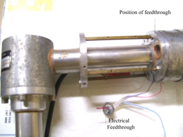
monitored by disconnecting the 9-pin low voltage PA power supply cable (Fig.11).
Generally, ±24V and ±12V power supplies are used to operate preamplifier, amplifier and
high voltage. If any one of the supply is not working, then either repair the BIN power supply
or replace it with a new working BIN power supply. A faulty power supply may damage the
FET or preamplifier components.
2.6.2. Identification of FET Failure Problem and its Replacement
FET has three pins, namely, Drain, Source and Gate. The Drain and Source points are
available on the preamplifier board but not Gate point. The Drain and Source form the
channel and conduction of this channel is controlled by the Gate voltage. In a non-
functioning FET, either the Gate to channel junction breaks or the channel becomes open.
The working FET shows Drain to Source channel resistance around 20Ω to 120Ω, which can
be measured on preamplifier board. Also, in one of the increase in leakage current problem,
FET replacement had resolved the problem.
2.6.3. FET Replacement
Since FET is placed in high vacuum jacket enclosing the cold finger and detector crystal
(Fig.14), the vacuum of the detector has to be purged for FET replacement. The vacuum is
leaked with the use of proper vacuum coupling in presence of Nitrogen gas (easily removable
gas during evacuation) to avoid fix contamination in vacuum jacket. Also, FET is specific
component used for low noise and it is being selected by measuring its trans-conductance
(gm) and Drain to Source channel resistance (rDS). After removing the faulty FET with a
spare one, the detector has to be re-evacuated to a vacuum level of ~10-7 mbar.
So, a re-evacuation facility was developed in Radiochemistry division to refurbish HPGe
detectors [5]. The evacuation system consists of Rotary pump, Turbo Molecular pump,
Vacuum Gauge and a controller unit (Fig.12). Also, to evacuate the detector, special vacuum
couplings are required. Presently, we have HPGe detectors of various models manufactured
by Ortec, Eurisys, Baltic and DSG firms. Since, the adapters are specific for each model,
the corresponding adapters were either procured or fabricated. The adapters are listed in
(Fig.13). The inlet port of the evacuation system (KF-25) has to be coupled to the detector
port through a vacuum adapter with a plunger to open and close the port. After
connecting the adapter, plunger is to be opened slowly and smoothly so that detector
chamber is connected to vacuum system for evacuation.
2.7. Detector Cooling Problems
The detector is cooled to liquid nitrogen temperature of 77 K to reduce the thermal leakage
current in the HPGe semiconductor detector which has very low band gap as compare to
other semiconductor detectors. Thus, detector crystal surface is at 77 K and detector
enclosure (cap) surface is at room temperature (300 K). For maintaining the thermal isolation
9of the crystal, detector is kept in vacuum. Vacuum also provides an electrical isolation
between the crystal and the casing, thereby minimizing the chances of HV discharge. For
proper functioning of the detector, a vacuum level is maintained at around 10-6 mbar [4].
2.7.1. Vacuum Leak in Detector Enclosure
The leak in detector enclosure vacuum degrades the temperature gradient. So, surrounding
(room) moisture gets deposited on the surface of the detector in the form of big water droplets
frequently even on removing. Also, the liquid nitrogen loss is found to be increased. This
confirms the vacuum leak problem.
a. One of the Eurysis make HPGe detectors was having a major problem of moisture
condensation over the surface because of vacuum leak in the detector enclosure (made up
of aluminum). The preliminary tests were conducted to find the leak like replacement of
O-ring etc., but in vain. A sniffing mode of He-leak detection system was used to detect
the leaks. The leak positions, obtained during this test, were removed by painting the
surface with vacuum paint (Torr Seal). However, it could improve the vacuum up to
6.1 x 10⁻¹ mbar. This vacuum was insufficient to operate HPGe Detector.
Then, a new similar detector cap was fabricated and mounted properly. Then, the
detector system was evacuated up to 2.5 x 10⁻⁵ mbar vacuum. The proper holding of
vacuum was tested by cooling the detector to Liquid Nitrogen temperature (77°K). After
confirming no vacuum leak in the detector enclosure, the system was properly reinstalled
and tested. Also it was observed that due to moisture condensation over the preamplifier
board, the tracks and the contacts were rusted. Thus 30% of the preamplifier board was in
bad condition and it was very difficult to repair. Hence a new spare preamplifier board
(Model- PSC822) was installed. The preamplifier power was applied to the detector
system. The 250 mV noise with 20 mV DC shift was measured at the preamplifier output.
Also it was responding properly with applied detector bias. With all fine adjustment like
FET drain current, pole zero, dead time etc, the detector resolution, 2.3 keV at 1332 keV,
was achieved.
b. Similarly in other Eurysis make coaxial detector, excessive sweating was observed over
the detector surface. Vacuum leaks were detected and at feed through of HV and FET
connecting pins. These leaks were traced using Helium leak detector and were sealed
using torr-seal sealant in suction mode. Then detector was evacuated at 3.4 x 10⁻⁵ mbar.
Thus, the sweating problem has been worked out.
c. Moisture accumulation was observed on LN2 Dewar. It was due to poor vacuum in
Dewar. Dewar was evacuated to the vacuum level of 10-3 mbar.
2.7.2. Liquid N2 Filling Problem in Dewar of HPGe Detector
Ice formation in the Liquid N2 Dewar was blocking the Liquid N2 filling port. Detector was
taken out from the Dewar to remove ice and kept outside for two days to undergo thermal
recycling as suggested earlier. After this, the detector system was reinstalled. This problem
usually occurs during filling of empty Dewar because of presence of humid air inside the
10Dewar. So, to overcome this problem, users had been suggested to pass dry air through the
Dewar for at least 10 to 15 min to drive out the humid air, before filling liquid N2.
2.7.3. High Liquid Nitrogen Evaporation Rate
In one of the detector, the dewar was getting empty at a faster rate. On inspection, it was
found that the detector collar (made up of rubber) was ruptured. It was responsible for high
rate of liquid nitrogen evaporation. A collar of similar dimension was fabricated with Teflon
and mounted on the Dewar with neoprene rubber gasket at both end of Teflon collar.
3. CONCLUSION
Most of the HPGe detectors have problems like increase in leakage current, vacuum leak
problems and failure of electronics component like FET, feedback resistor and capacitor kept
inside the vacuum. Causes to all these electronic problems have been discussed along with
solutions. Most of the spares are replaced and detectors are made functional. To resolve FET
related problems in HPGe detectors of different makes, a refurbishment facility was
developed in Radiochemistry division using a high vacuum pumping system. Using this
facility, several non-working HPGe detectors were brought to working condition with desired
resolution.
ACKNOWLEDGEMENT
The authors thank Dr. P.K. Pujari, Director, RC&IG & Head Radiochemistry Division for his
keen interest and encouragement for above activities. The authors are thankful to
Dr. S.K. Gupta of NPD, BARC for providing Helium leak detection facility during
refurbishment of HPGe detector. Acknowledgements are also to Dr. Rahul Tripathi, Head,
Nuclear Chemistry section and Dr. Kathi Sudarshan, Head, Nuclear Probes section, for their
valuable guidance during evacuation of the system and testing of the rectified detectors. The
authors also thank their colleagues of Equipment Electronic Services Section for their
constant support during the breakdown maintenance.
11REFERENCES
[1] Knoll, G.F. “Radiation detection and measurement”, 3rd Ed., New York: John Wiley,
2000.
[2] “Solid-State Photon Detector: Operators manual, GLP Series, HPGe (High-
Purity Germanium) low-energy photon spectrometer”, EG & G ORTEC, Oak
Ridge, U.S.A., 1986.
[3] “Germanium Detectors: User’s manual”, Canberra Industries, Inc., Meriden, U.S.A.,
2002.
[4] “HPGe detector manual: Operating instructions and funktion of HPGe detector”,
DSG Detector Systems GmbH, Mainz, Germany, 2005
[5] Chaturvedi, T.P., Tawade, N.S., and Venkiteswaran, S. “Setting up of a facility for
refurbishment of HPGe detectors at Radiochemistry Lab., BARC”, In: DAE-BRNS
symposium on nuclear and radiochemistry (NUCAR 2009), (Mumbai, India: NUCAR
2009, January 7-10, 2009), edited by A.R. Joshi et al., pp. 641-642, 2009.
12Fig.1. HPGe Detector based Gamma Radiation Detection System [2]
Fig.2. HPGe Detector based Gamma Radiation Detection System with modules [3]
13Moisture
condensation at
electrical feed
through
Fig.3. Moisture condensation over detector enclosure and electrical feed through
during shutdown
a. Before applying High Voltage b. After application of High Voltage
Fig.4. Preamplifier output signal
Fig.5. The electrical feed through replacement
14Fig.6. Graph of Leakage current and detector capacitance V/s applied voltage [3]
Fig.7. Transverse section of HPGe Detector [1 & 3]
15Replaced new components Faulty Components
Fig.8. Picture of feedback components register and capacitor
Eurysis Detector Ortec Detector DSG Detector
Fig.9. Picture of High Voltage filter modules
16Fig.10. Pole Zero adjustment process [2]
17Fig.11. Picture of preamplifier cable [3]
Fig.12. Turbo molecular based high vacuum HPGe Detector evacuating System
18Vacuum port for Ortec Detector Vacuum port for Baltic Detector
Vacuum port for Eurysis Detector
Vacuum port for old Canberra detector Vacuum port for DSG Detector
Fig.13. Photograph of different vacuum port used for Detector evacuation
19Fig.14. Internal part of HPGe detector kept in vacuum 20
You can also read