DSC 401 and DSC 401 A - User Guide Scalers - Extron
←
→
Page content transcription
If your browser does not render page correctly, please read the page content below
User Guide
                                   Scalers

DSC 401 and
DSC 401 A
4K/60 HDMI to HDMI Scalers

                                   68-3539-01 Rev. A
                                               04 21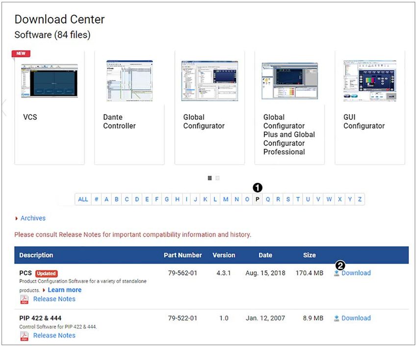
Copyright
© 2021 Extron. All rights reserved. www.extron.com

Trademarks
All trademarks mentioned in this guide are the properties of their respective owners.
The following registered trademarks (®), registered service marks (SM), and trademarks (TM) are the property of RGB Systems, Inc. or Extron (see the
current list of trademarks on the Terms of Use page at www.extron.com):

                                                              Registered Trademarks (®)
 Extron, Cable Cubby, ControlScript, CrossPoint, DTP, eBUS, EDID Manager, EDID Minder, eLink, Flat Field, FlexOS, Glitch Free, Global Configurator,
 Global Scripter, GlobalViewer, Hideaway, HyperLane, IP Intercom, IP Link, Key Minder, LinkLicense, LockIt, MediaLink, MediaPort, NAV,
 NetPA, PlenumVault, PoleVault, PowerCage, PURE3, Quantum, ShareLink, Show Me, SoundField, SpeedMount, SpeedSwitch, StudioStation,
 System INTEGRATOR, TeamWork, TouchLink, V‑Lock, VideoLounge, VN‑Matrix, VoiceLift, WallVault, WindoWall, XPA, XTP, XTP Systems, and ZipClip
 Registered Service Mark(SM) : S3 Service Support Solutions
                                                                    Trademarks (™)
 AAP, AFL (Accu‑RATE Frame Lock), ADSP (Advanced Digital Sync Processing), AVEdge, CableCover, CDRS (Class D Ripple Suppression),
 Codec Connect, DDSP (Digital Display Sync Processing), DMI (Dynamic Motion Interpolation), Driver Configurator, DSP Configurator, DSVP (Digital
 Sync Validation Processing), EQIP, Everlast, FastBite, Flex55, FOX, FOXBOX, IP Intercom HelpDesk, MAAP, MicroDigital, Opti‑Torque,
 PendantConnect, ProDSP, QS‑FPC (QuickSwitch Front Panel Controller), Room Agent, Scope‑Trigger, SIS, Simple Instruction Set, Skew‑Free,
 SpeedNav, Triple‑Action Switching, True4K, True8K, Vector™ 4K, WebShare, XTRA, and ZipCaddy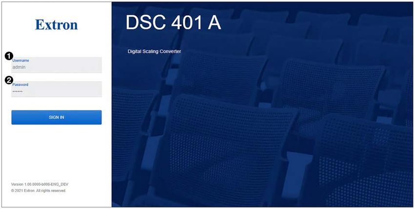
FCC Class A Notice
                This equipment has been tested and found to comply with the limits for a Class A digital
                device, pursuant to part 15 of the FCC rules. The Class A limits provide reasonable
                protection against harmful interference when the equipment is operated in a commercial
                environment. This equipment generates, uses, and can radiate radio frequency energy and,
                if not installed and used in accordance with the instruction manual, may cause harmful
                interference to radio communications. Operation of this equipment in a residential area is
                likely to cause interference. This interference must be corrected at the expense of the user.

                 NOTE: For more information on safety guidelines, regulatory compliances, EMI/EMF
                   compatibility, accessibility, and related topics, see the Extron Safety and Regulatory
                   Compliance Guide on the Extron website.

VCCI-A Notice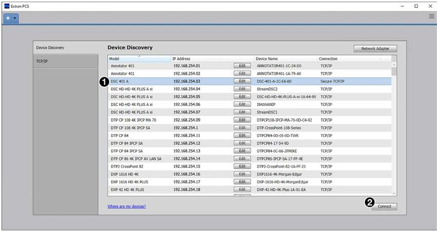
Conventions Used in this Guide
     Notifications
                 The following notifications are used in this guide:

                     CAUTION:		        Risk of minor personal injury.
                     ATTENTION :       Risque de blessure mineure.

                     ATTENTION:
                        • Risk of property damage.
                        • Risque de dommages matériels.

                     NOTE: A note draws attention to important information.

     Software Commands
                 Commands are written in the fonts shown here:
                       ^AR Merge Scene,,0p1 scene 1,1 ^B 51 ^W^C.0
                       [01] R 0004 00300 00400 00800 00600 [02] 35 [17] [03]
                       E X! *X1&* X2)* X2#* X2! CE}
                        NOTE: For commands and examples of computer or device responses used in this
                          guide, the character “0” is the number zero and “O” is the capital letter “o.”
                 Computer responses and directory paths that do not have variables are written in the font
                 shown here:
                       Reply from 208.132.180.48: bytes=32 times=2ms TTL=32
                       C:\Program Files\Extron
                 Variables are written in slanted form as shown here:
                       ping xxx.xxx.xxx.xxx —t
                       SOH R Data STX Command ETB ETX
                 Selectable items, such as menu names, menu options, buttons, tabs, and field names are
                 written in the font shown here:
                       From the File menu, select New.
                       Click the OK button.

Specifications Availability
                 Product specifications are available on the Extron website, www.extron.com.

Extron Glossary of Terms
                 A glossary of terms is available at http://www.extron.com/technology/glossary.aspx.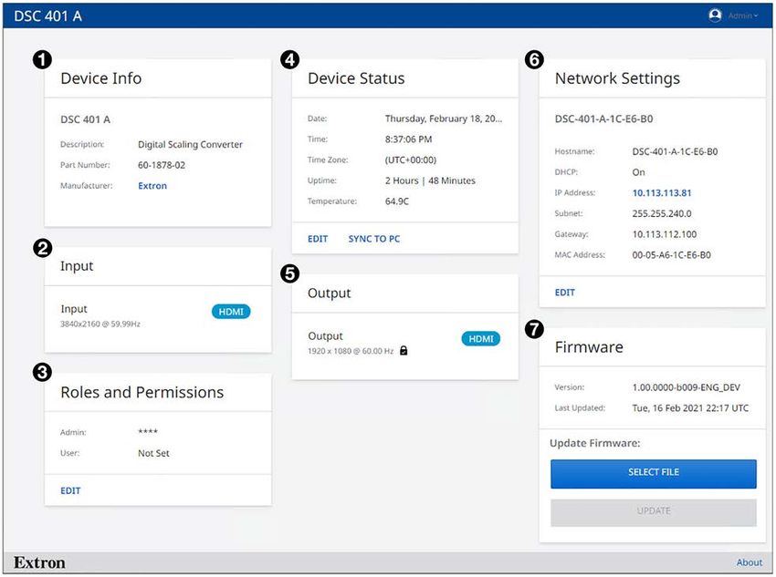
Contents
Introduction............................................................ 1 Remote Configuration and Control................. 37
About this Guide.................................................. 1 SIS Commands................................................. 37
Features.............................................................. 2 Connecting the DSC to the Host................... 37
DSC 401 A Only Features................................ 4 Initial Power Up Messages............................. 38
Application Diagrams........................................... 5 Password Messages..................................... 38
DSC-initiated Messages................................ 39
Installation............................................................... 6 Error Responses............................................ 39
Installation Overview............................................ 6 Using the Command and Response Table..... 40
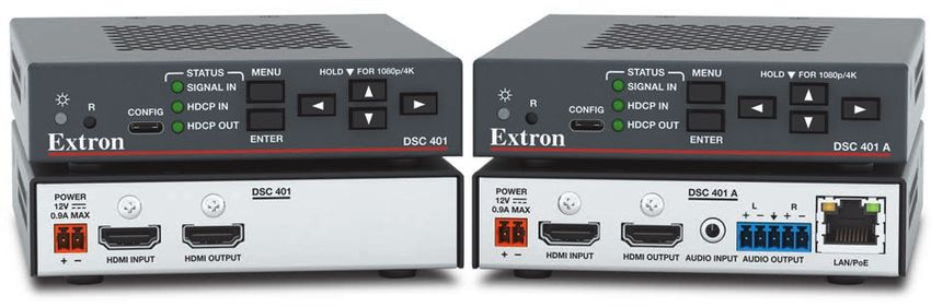
Rear Panel Features............................................ 7 Symbol Definitions......................................... 41
Wiring the Power Supply..................................... 9 Command and Response Table for SIS
Securing the HDMI Connector Using the Commands...................................................... 48
LockIt Cable Lacing Bracket ............................ 11 CEC Commands — DSC 401 A Only................ 67
Symbol Definitions for CEC
Communications Commands....................... 67
Operation............................................................... 12
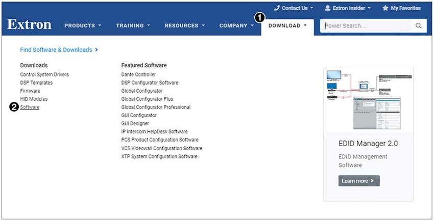
Product Configuration Software (PCS)
Front Panel Features.......................................... 12 Program........................................................... 70
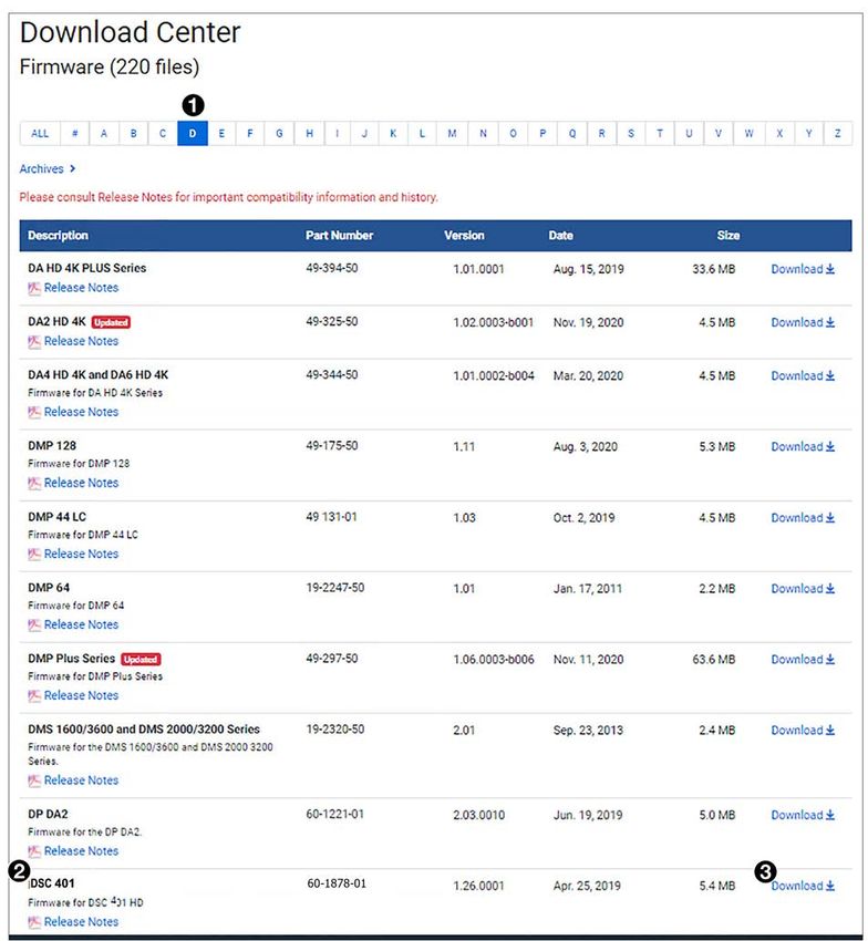
Powering On..................................................... 13 Downloading PCS from the Website.............. 70
On-screen Display (OSD) Menu......................... 13 Starting the Configuration Program................ 72
Menu Overview.............................................. 13 Updating Firmware............................................ 75
Using the OSD Menu..................................... 14
Device Info Screen......................................... 16
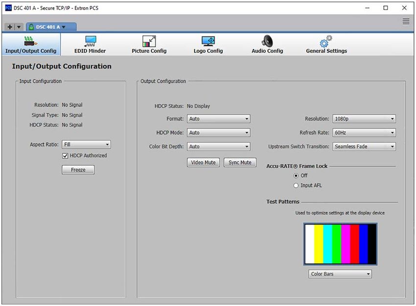
Internal Web Page............................................... 76
Quick Setup Submenu.................................. 17
Web Page Components.................................... 77
Picture Controls Submenu (DSC 401 A
Only)............................................................. 18 Device Info Panel........................................... 78
Input Submenu.............................................. 20 Input Panel ................................................... 78
Output Submenu........................................... 23 Roles and Permissions Panel......................... 78
Audio Submenu............................................. 27 Device Status Panel....................................... 79
Advanced Submenu...................................... 29 Output Panel ................................................ 81
Communications Submenu........................... 31 Network Settings Panel (DSC 401 A Only)..... 81
Image Reset (DSC 401 A Only).......................... 32 Firmware Panel.............................................. 82
Changing the Output Resolution and Refresh
Rate................................................................. 33 Reference Information....................................... 84
Custom Rates............................................... 33 Mounting the DSC............................................. 84
Resetting the Output Rate ............................ 33 Downloading Firmware...................................... 85
Power Save Mode............................................. 34
Switching Transitions......................................... 34
CEC Control (DSC 401 A Only).......................... 34
Presets.............................................................. 35
Locking the Front Panel (Executive Mode)......... 35
Resetting........................................................... 36
DSC 401 and 401 A User Guide • Contents vii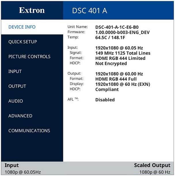
DSC 401 and 401 A User Guide • Contents viii
Introduction

              This section provides an overview of the DSC 401 and DSC 401 A scalers, covering the
              following topics:
              •    About this Guide
              •    About the DSC 401 and DSC 401 A
              •    Features
              •    Application Diagrams

About this Guide
              The DSC 401 and DSC 401 A User Guide describes the Extron DSC HDMI-to-HDMI Digital
              Scaling Converters and provides instructions for experienced installers to install, configure,
              and operate them.
              In this guide, the terms “scaler” and “DSC” are used interchangeably to refer to either of the
              DSC 401 and 401 A models.

About the DSC 401 and DSC 401 A
              The Extron DSC 401 and DSC 401 A are high-performance scalers capable of converting
              between HDMI resolutions up to 4K @ 60 Hz with full 4:4:4 color sampling. They
              support data rates up to 18 Gbps and incorporate the Extron-exclusive Vector™ 4K
              scaling technology, which is engineered for critical-quality 4K applications. Both HDCP
              2.3‑compliant models support 4K @ 60 Hz signals on a single connection.
              The scalers feature on‑screen displays, internal test patterns, and status LEDs. The
              DSC 401 A model also features audio embedding and de‑embedding, logo image keying
              and display, input presets, audio file playback, and Ethernet control with PoE. The DSC 401
              and DSC 401 A scalers are ideal for locations such as conference rooms, auditoriums, or
              anywhere high-quality 4K scaling of HDMI signals is required.
              Both scalers feature front panel controls for quick access to functions. Additionally, LED
              indicators on the front panel provide visual confirmation of video input signals, the presence
              of HDCP encryption, reset levels, and power. Remote configuration is available via USB-C
              on both models. The DSC 401 A can be configured or controlled externally over Ethernet.
              Each scaler is housed in a compact, 1-inch, quarter-rack wide metal enclosure.

                                                DSC 401 and DSC 401 A User Guide • Introduction            1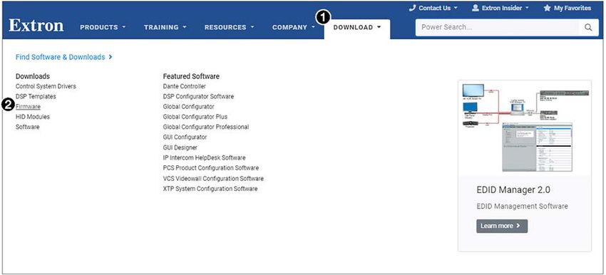
Features
           •   4K @ 60 Hz HDMI to HDMI scaling — The DSC 401 and DSC 401 A scalers provide
               high quality scaling of HDMI video resolutions and frame rates.
           •   Connectors —
               •   Input — One female HDMI Type A
               •   Audio Input (DSC 401 A only) — One 3.5 mm stereo mini jack
               •   Output — One female HDMI Type A
               •   Audio Output (DSC 401 A only) — One balanced and unbalanced stereo audio
                   on 5‑pole captive screw
           •   Advanced Extron Vector 4K scaling engine — The Vector 4K scaling engine is
               specifically designed for critical-quality 4K imagery, with best-in-class image upscaling
               and downscaling.
           •   HDCP 2.3 compliant — Ensures display of content-protected media and
               interoperability with other HDCP‑compliant devices.
           •   Advanced 4:4:4 signal processing — 4:4:4 signal processing maintains color
               accuracy and fine picture detail.
           •   Input resolutions — Accepts HDMI video from 480i up to 4096x2160 @ 4:4:4.
           •   Selectable output rates from 640x480 up to 4096x2160 @ 4:4:4.
           •   Supported HDMI specification features include data rates up to 18 Gbps, Deep
               Color, and HD lossless audio formats
           •   Motion-adaptive deinterlacing — Advanced deinterlacing for all interlaced signals up
               to 1080i delivers optimized image quality.
           •   Seamless transitions — Automatically applies a seamless fade or cut when a new
               source is detected.
           •   Automatic 3:2 and 2:2 pulldown detection — Advanced film mode processing
               techniques instantaneously detect and maximize image quality for NTSC, PAL, and
               1080i sources that originated from film.
           •   User-selectable HDCP authorization — Allows the unit to appear HDCP compliant
               or non‑HDCP compliant to the connected source, which is beneficial if the source
               automatically encrypts all content when connected to an HDCP‑compliant device.
               Protected material is not passed in non‑HDCP mode.
           •   EDID Minder — EDID Minder ensures that the source powers up properly and reliably
               outputs content for display. It manages EDID communication between connected
               devices.
           •   Custom EDID and output resolutions — User-defined output resolutions up to
               600 MHz pixel clock can be supported by uploading custom EDID files or capturing
               EDID from a display or other destination device.
           •   Aspect ratio control — The aspect ratio of the video output can be controlled by
               selecting a FILL mode, which provides a full-screen output, or a FOLLOW mode, which
               preserves the original aspect ratio of the input signal.
           •   Scaler Bypass Mode — Allows scaling to be bypassed to support unprocessed
               transmission of 3D, HDR, and other formats.
           •   HDCP authentication and signal presence confirmation — Provides real-time
               verification of HDCP status for each digital video input and output. This allows for quick
               and easy signal and HDCP verification through USB or Ethernet, providing feedback to
               a system operator or helpdesk support staff.

                                              DSC 401 and DSC 401 A User Guide • Introduction               2
• HDCP Visual Confirmation — When HDCP‑encrypted content is transmitted to
a non‑HDCP compliant display, a full‑screen green signal or user-supplied image is
sent to the display for immediate visual confirmation that protected content cannot be
viewed on that display.
• HDMI to DVI Interface Format Correction — Automatically enables or disables
embedded audio and InfoFrames, and sets the correct color space for proper
connection to HDMI and DVI displays.
• HDMI audio de‑embedding — Embedded HDMI two‑channel PCM audio can be
extracted to the analog output, or multi‑channel and bitstream formats can be passed
to the HDMI output.
• On‑screen menus — On‑screen menus enable system setup using the front panel
controls. Key parameters such as input and output video formats are conveniently
grouped on the initial Quick Setup screen, while additional screens provide full control
over the other functions and settings.
• Output standby mode — Can be set to mute video and sync output to the display
device when no active input signal is detected. This allows the projector or display to
automatically enter into standby mode to save energy and enhance lamp or panel life.
• Power Save Mode — Can be placed in a low-power standby state to conserve energy
when not in use.
• Internal video test patterns for calibration and setup — The scalers offer five video
test patterns to facilitate proper system setup and calibration of display devices. These
include crop, alternating pixels, crosshatch, color bars, and grayscale. The DSC 401 A
also includes pink noise for audio testing.
• Automatic input cable equalization — Conditions incoming HDMI signals to
compensate for signal loss when long cables, low quality cables, or source devices with
poor signal output are used.
• Logo image keying and display (DSC 401 A only) — A logo graphic can be
positioned and keyed over live video. Logo graphics in BMP, GIF, JPG, PNG, or TIFF
format can be uploaded to the unit. Full screen images up to 4K resolution can also be
displayed to eliminate loss of video between presentations.
• Integrated audio delay — The audio output is automatically delayed to compensate
for latency introduced by video processing.
• Selectable audio muting — Embedded HDMI audio can be muted, and the analog
audio output on the DSC 401 A can also be muted.
• Front panel security lockout — Locks out front panel functions. All functions remain
available through Ethernet or USB.
• Built‑in internal web page — Enables the use of a standard browser for monitoring,
troubleshooting, and firmware updates over an intuitive web interface.
• Front panel USB configuration port — Provides convenient access for setup,
configuration, and firmware updates.
• Real-time status LED indicators for troubleshooting and monitoring — LED
indicators on the front panel provide visual confirmation of input signal presence, HDCP
authentication, and power status.
• Product Configuration Software (PCS) — Conveniently configure multiple products
using a single software application.
• 1 inch (250 mm) high, quarter rack wide metal enclosure
• Includes LockIt HDMI cable lacing brackets
• External Extron Everlast power supply — Provides worldwide power compatibility
with high reliability and low power consumption. Extron Everlast Power Supply is
covered by a 7‑year parts and labor warranty.
DSC 401 and DSC 401 A User Guide • Introduction 3DSC 401 A Only Features
• HDMI audio embedding — Audio from the two‑channel analog input can be
embedded onto the HDMI output.
• Accu-RATE Frame Lock (AFL) — This patented Extron technology locks the output
frame rate to the input to eliminate stuttering caused by frame rate conversion.
• Image freeze control — A live image can be frozen using USB or Ethernet control.
• Auto Input Memory — When activated, the unit stores size, position, and picture
settings based on the incoming signal. When the same signal is detected again, these
image settings are automatically recalled from memory.
• Picture controls for horizontal and vertical sizing and positioning
• Output volume control — Provides master volume control for the analog and HDMI
embedded audio outputs.
• Audio input gain and attenuation — Gain and attenuation can be adjusted for the
analog audio input.
• Audio file playback — Up to 16 pre‑recorded messages can be stored and played
back over HDMI-embedded and analog outputs. Supported audio file types include
WAV, MP3, AAC, and more.
• Consumer Electronics Control capability (CEC) — Standard, built‑in CEC
commands can be triggered to control displays or other AV devices connected
over HDMI. The ability to control specific functions, such as power on and off, input
selection, or volume level, is dependent on implementation by the device manufacturer.
• Ethernet monitoring and control — Enables control and monitoring over a LAN or
WAN. An intuitive web interface is included for system monitoring and firmware updates.
• Power over Ethernet (PoE) — PoE allows the DSC 401 A to receive power and
communication over a single Ethernet cable, eliminating the need for a local power
supply.
DSC 401 and DSC 401 A User Guide • Introduction 4Application Diagrams
HD VC Codec
MODEL 80
Extron
HDMI 1080p DTP2 R 211 HDMI 4K
4K/60 HDMI
Extron DTP2 Receiver
DSC 401
POWER DSC 401
12V SIG LINK
0.9A MAX OUTPUTS FLAT PANEL
POWER OVER DTP2
12V AUDIO
4K/60 HDMI to
--A MAX RS-232 IR L R
HDMI INPUT HDMI OUTPUT DTP2 IN
4K Display
HDMI Scaler
Tx Rx G Tx Rx
CATx Cable
up to 330' (100 m)
HDMI 4K
Audio
Extron DTP2 CROSSPOINT 82 IPCP SA
COM 1 COM 2 COM 3 DIGITAL I/O
AV LAN 2 AV LAN 3
AMPLIFIED OUTPUT
2x25W(8Ω)/2x50W(4Ω)
DTP2 CrossPoint 82
L R
Tx Rx G RTS CTS Tx Rx G Tx Rx G 1 2 3 4 G
IR/SERIAL RELAYS eBUS
1 2 1 2 C 3 4 C +V +S -S G
IPCP SA
R
CLASS 2 WIRING
S G S G PWR OUT = 6W
LAN AV LAN 1
8x2 4K/60 Scaling 100-240V~ --A MAX
Presentation Matrix
2 HDMI 4 HDMI 6 HDMI
7 8 1 2
L R +48V
1 1 2
SIG LINK SIG LINK SIG LINK
OVER TP AUX
MIC/LINE
Switcher
LOOP OUT IR 3 4 2 3 4 RS-232 RESET
1 DP 3 HDMI 5 HDMI
+48V
50-60 Hz
HDMI HDMI/CEC Tx Rx G Tx Rx G
IN IN OUT
INPUTS (DTP2/XTP) OUTPUTS (DTP2/XTP/HDBT) AUDIO INPUTS OUTPUTS REMOTE
E E
Extron
SM 26
Surface Mount
Speakers
HDMI 4K
Laptop
HDMI 1080p
Blu-ray Player
2
1
HDMI 4K HDMI 4K
4K Media Player Workstation PC
Figure 1. DSC 401 Application Example
Audio
Extron
XPA U 1002
MODEL 80
POWER AMPLIFIERS
E E
OVER
TEMP 1 2
Power Amplifier Extron
LIMITER/PROTECT
SIGNAL
XPA U 1002 SERIES
SM 26
Surface Mount
HDMI 4K Audio Speakers
FLAT PANEL
POWER
12V
DSC 401 A
L R Extron
DSC 401 A
0.9A MAX
4K Display
4K/60 HDMI to HDMI Scaler
HDMI INPUT HDMI OUTPUT AUDIO INPUT AUDIO OUTPUT LAN/PoE
HDMI with Audio Embedding and
De-embedding
SW4 HD 4K PLUS
Extron
SW4 HD 4K PLUS POWER
12V 1 2
INPUTS
3 4
OUTPUT REMOTE LAN
Four Input 4K/60
0.5A MAX 1 2 3 4 RS-232
HDMI Switcher
C T C T +V C T C T Tx Rx G
HDMI 4K HDMI 4K
2
1
Workstation PC
Ultra HD Blu-ray Player
HDMI 4K HDMI
4K Media Player Laptop
Figure 2. DSC 401 A Application Example
DSC 401 and DSC 401 A User Guide • Introduction 5Installation
This section provides a description of the DSC 401 and 401 A rear panel connectors and
instructions for cabling. Topics include:
• Installation Overview
• Rear Panel Features
• Wiring the Power Supply
• Securing the HDMI Connector Using the LockIt Cable Lacing Bracket
ATTENTION:
• Installation and service must be performed by authorized personnel only.
• L’installation et l’entretien doivent être effectués uniquement par un électricien
qualifié.
Installation Overview
1. Disconnect power — Turn off or disconnect all equipment power sources.
2. Mount the unit (optional) — Mount the DSC in a rack using a shelf mounting
bracket kit or under furniture using a furniture mounting bracket kit, available at
www.extron.com (see the instructions provided with the kit).
3. Connect the HDMI video input and output — Connect an HDMI video source
and display to the HDMI input (see figures 3 and 4, B) and output (C) connectors.
Secure each HDMI device to the connector with a provided LockIt® bracket (see
Securing the HDMI Connector Using the LockIt Cable Lacing Bracket on
page 11).
4. Connect analog audio input (DSC 401 A only, optional) — Connect an analog audio
source to the 3.5 mm TRS Audio Input connector (D).
5. Connect an audio output device (DSC 401 A only, optional) — Connect an amplifier
or audio system to the 5-pole captive screw Audio Output connector (E) for balanced
or unbalanced stereo or mono audio output.
The output can contain de-embedded audio from the input source (two-channel LPCM
only) or the analog input can pass through. The analog output and the embedded digital
audio outputs share volume adjustment controls (applies to analog or LPCM-2Ch inputs
only). If multi-channel formats (such as Dolby/DTS or multi-channel PCM audio) are
used, the analog output is muted and volume control has no effect on the output.
6. Connect to a network (DSC 401 A only, optional) — For remote control, connect
the unit to a network via the RJ-45 LAN/PoE connector (F), enabling configuration of
the DSC via SIS commands, PCS or Toolbelt software, or the DSC 401 and 401 A web
page. The LAN port supports PoE, which allows PoE network equipment to power the
DSC 401 A.
NOTE: An external power supply is not required for a DSC 401 A using PoE.
7. If not using the provided pre-wired power supply, wire a 2-pole captive screw connector
(provided) to your power supply (see Wiring the Power Supply on page 9).
DSC 401 and DSC 401 A User Guide • Installation 6Rear Panel Features
CAUTION: Remove power from the system before wiring.
ATTENTION : Coupez l’alimentation avant de faire l’installation électrique.
ATTENTION:
• Use electrostatic discharge precautions (be electrically grounded) when making
connections. Electrostatic discharge (ESD) can damage equipment, although
you may not feel, see, or hear it.
• Prenez des précautions contre les décharges électrostatiques (soyez
électriquement relié à la terre) lorsque vous effectuez des connexions. Les
décharges électrostatiques (ESD) peuvent endommager l’équipement, même si
vous ne pouvez pas le sentir, le voir ou l’entendre.
POWER DSC 401
12V
0.9A MAX
HDMI INPUT HDMI OUTPUT
A B C
A Power connector
B HDMI input connector
C HDMI output connector
Figure 3. Rear Panel — DSC 401
POWER DSC 401 A
12V L R
0.9A MAX
HDMI INPUT HDMI OUTPUT AUDIO INPUT AUDIO OUTPUT LAN/PoE
A B C D E F
A Power connector D Audio input connector
B HDMI input connector E Audio output connector
C HDMI output connector F Ethernet LAN connector with PoE
Figure 4. Rear Panel — DSC 401 A
A Power connector (see figure 3 or figure 4) — Plug the provided external 12 VDC, 1.5
A power supply into this 2-pole, 3.5 mm captive screw connector and into an AC power
outlet.
If not using the provided pre-wired power supply, wire a 2-pole captive screw connector
(provided) to your power supply (see Wiring the Power Supply on page 9.)
See the ATTENTION notices starting on page 9 before wiring the captive screw
connectors described in this section.
DSC 401 and DSC 401 A User Guide • Installation 7B HDMI input connector — This HDMI 1.4/2.0 video input supports pixel clocks up
to 600 MHz, deep color, factory and custom EDIDs, LPCM audio de-embedding
(DSC 401 A only), and HDCP 1.4 and 2.3. DVI signals are supported with an
appropriate adapter.
You can enable or disable HDCP authorization using the OSD menu system (see
Input Submenu on page 20), SIS commands (see HDCP Encryption Support
commands on page 49), or PCS (see the DSC 401 and 401 A Help File).
Secure the HDMI input cable to the HDMI connector using the LockIt bracket (see
Securing the HDMI Connector Using the LockIt Cable Lacing Bracket on
page 11).
C HDMI output connector — This HDMI 1.4/2.0 video output supports pixel clocks up
to 600 MHz, deep color, sink device presence, read and save sink EDID, HDCP 1.4 and
2.3, HDCP compliance status, LPCM audio embedding, DVI signaling (up to 165 MHz
pixel clock), pass-through of embedded multi-channel audio (DTS-HD, Dolby formats,
and so on), and configurable RGB and YUV color spaces.
Secure the HDMI output cable to the HDMI connector using the LockIt bracket (see
Securing the HDMI Connector Using the LockIt Cable Lacing Bracket).
D Audio input connector — (DSC 401 A only) If desired, Tip (+)
connect a 2-channel balanced or unbalanced analog
audio source to this 3.5 mm analog audio TRS connector
to embed analog audio in the HDMI output signal (see the
image at right).
Sleeve ( )
Input gain range is -18 dB to +24 dB. The default is 0 dB.
E Audio output connector — (DSC 401 A only) Connect an amplifier or audio system to
this 5-pole captive screw connector for analog output as shown in figure 5.
No Ground Here
Tip
L
Ring
L
Tip
Sleeves Sleeves
Tip Tip
Ring
R
R
No Ground Here
Balanced Audio Output Unbalanced Audio Output
Figure 5. Wiring the Audio Output Connector
ATTENTION:
• For unbalanced audio, connect the sleeves to the ground contact. Do not
connect them to negative (–) contacts.
• Pour l’audio asymétrique, connectez les manchons au contact au sol. Ne
PAS connecter les manchons aux contacts négatifs (–).
F Ethernet LAN connector with PoE (see figure 6 on page 9) — (DSC 401 A
only) Plug an Ethernet cable into this RJ-45 jack to connect the unit to a computer
network. Ethernet control allows you to configure and control the DSC from a remote
location using SIS commands, the PCS software, or the embedded web pages. When
connected to an Ethernet LAN, the DSC can be accessed from a computer running
a standard Internet browser. Use a patch or crossover cable to connect the DSC to a
switch, router, or computer (figure 6).
In addition, the LAN port supports power over Ethernet, which allows PoE network
equipment to power the DSC 401 A. An external power supply is not required for a
DSC 401 A using PoE.
DSC 401 and DSC 401 A User Guide • Installation 8The LAN connector contains two LEDs (see the image at right): LAN
• Amber LED — This LED blinks to indicate LAN signal activity.
• Green LED — This LED lights steadily to indicate a LAN connection.
Pins: Crossover Cable Straight-through Cable
12345678
End 1 End 2 End 1 End 2
Pin Wire color Wire color Pin Wire color Wire color
1 White-green White-orange 1 White-orange White-orange
2 Green Orange 2 Orange Orange
3 White-orange White-green 3 White-green White-green
4 Blue Blue 4 Blue Blue
5 White-blue White-blue 5 White-blue White-blue
6 Orange Green 6 Green Green
7 White-brown White-brown 7 White-brown White-brown
Insert Twisted 8 Brown Brown 8 Brown Brown
Pair Wires T568A T568B T568B T568B
RJ-45 A cable that is wired as T568A at one end A cable that is wired the same at both ends
Connector
and T568B at the other (Tx and Rx pairs is called a "straight-through" cable, because
reversed) is a "crossover" cable. no pin or pair assignments are swapped.
Figure 6. Connecting to the LAN Port
NOTES:
• The SIS over SSH port 22023 is enabled by default to send SIS commands
via IP over USB.
• By default Telnet communication on TCP port 23 is disabled on the
DSC 401 A. You can enable Telnet over port 23 if Telnet is required for
communication (such as sending SIS commands and responses) between
the DSC 401 A and the control system or PC. Connect the DSC directly
to the PC and use SIS commands to enable the port (see Telnet Port on
page 66), then reconnect the unit to the LAN or WAN.
Wiring the Power Supply
A 12 VDC, 1.5 A, pre-wired power supply is provided with the DSC 401 and 401 A. If you
intend to use a different power supply, follow the power wiring instructions on page 11 to
wire the provided 2-pole captive screw connector to your power supply.
ATTENTION:
• The wires must be kept separate while the power supply is plugged in. Remove
power before wiring.
• Les deux cordons d’alimentation doivent être tenus à l’écart l’un de l’autre
quand l’alimentation est branchée. Couper l’alimentation avant de faire
l’installation électrique.
• Always use a power supply supplied and or specified by Extron. Use of an
unauthorized power supply voids all regulatory compliance certification and may
cause damage to the supply and the end product.
• Utilisez toujours une source d’alimentation fournie ou recommandée par Extron.
L’utilisation d’une source d’alimentation non autorisée annule toute conformité
réglementaire et peut endommager la source d’alimentation ainsi que le produit
final.
DSC 401 and DSC 401 A User Guide • Installation 9ATTENTION:
• The wires must be kept separate while the power supply is plugged in. Remove
power before wiring.
• Les deux cordons d’alimentation doivent être tenus à l’écart l’un de l’autre
quand l’alimentation est branchée. Couper l’alimentation avant de faire
l’installation électrique.
• If not provided with a power supply, this product is intended to be supplied by a
power source marked “Class 2” or “LPS” and rated at 12 VDC and a minimum
of 1.5 A, or 56/48 VDC (PoE) and a minimum of 0.8/0.35 A.
• Si ce produit ne dispose pas de sa propre source d’alimentation électrique, il doit
être alimenté par une source d’alimentation de classe 2 ou LPS et paramétré à
12 V et 1.5 A minimum, ou 56/48VDC (PoE) et 0.8/0.35 A minimum.
• The installation must always be in accordance with the applicable provisions of
National Electrical Code ANSI/NFPA 70, article 725 and the Canadian Electrical
Code part 1, section 16. The power supply shall not be permanently fixed to
building structure or similar structure.
• Cette installation doit toujours être en accord avec les mesures qui s’applique
au National Electrical Code ANSI/NFPA 70, article 725, et au Canadian Electrical
Code, partie 1, section 16. La source d’alimentation ne devra pas être fixée de
façon permanente à une structure de bâtiment ou à une structure similaire.
• Power supply voltage polarity is critical. Incorrect voltage polarity can damage
the power supply and the unit. The ridges on the side of the cord identify the
power cord negative lead (see figure 7 on page 11).
• La polarité de la source d’alimentation est primordiale. Une polarité incorrecte
pourrait endommager la source d’alimentation et l’unité. Les stries sur le côté
du cordon permettent de repérer le pôle négatif du cordon d’alimentation (voir
figure 7).
• To verify the polarity before connection, plug in the power supply with no load
and check the output with a voltmeter.
• Pour vérifier la polarité avant la connexion, brancher l’alimentation hors charge et
mesurer sa sortie avec un voltmètre.
• The length of the exposed (stripped) copper wires is important.
The ideal length is 3/16 inch (5 mm). Longer bare wires can short together.
Shorter wires are not as secure in the connectors and could be pulled out.
• La longueur des câbles exposés est primordiale lorsque l’on entreprend de les
dénuder. La longueur idéale est de 5 mm (3/16 inches). S’ils sont un peu plus
longs, les câbles exposés pourraient se toucher et provoquer un court circuit.
S’ils sont un peu plus courts, ils pourraient sortir, même s’ils sont attachés par
les vis captives.
• Do not tin the wires. Tinned wires are not as secure in the captive screw
terminals and could pull out.
• Ne pas étamer les câbles. Les câbles étamés ne sont pas aussi bien fixés dans
les borniers à vis et pourraient s’arracher.
• Unless otherwise stated, the AC/DC adapters are not suitable for use in air
handling spaces or in wall cavities.
• Sauf mention contraire, les adaptateurs AC/DC ne sont pas appropriés pour une
utilisation dans les espaces d’aération ou dans les cavités murales.
DSC 401 and DSC 401 A User Guide • Installation 10To wire the power supply:
1. Cut the DC output cord to the length needed.
2. Strip the jacket to expose 3/16 inches (5 mm) of the conductors.
3. Slide the leads into the supplied 2-pole captive screw plug, and use a small screwdriver
to secure them.
4. To verify the power cord polarity before connecting the plug, connect the power supply
with no load and check the output with a voltmeter.
5. Use the supplied tie wrap to strap the power cord to the extended tail of the connector.
POWER
A 12 V
1.5 A MAX
Smooth
Ridges
SECTION A–A 3/16"
A
(5 mm) Max.
Figure 7. Wiring the Power Connector
Securing the HDMI Connector Using the LockIt Cable Lacing Bracket
After connecting an input or output device to
an HDMI connector, secure the connector in
place with the provided LockIt bracket as
follows:
1. Plug the HDMI cable into the panel
2
connection (1). 1
2. Loosen the HDMI connection mounting
screw from the panel enough to allow the
LockIt lacing bracket to be placed over
it (2).
3
3. Place the LockIt lacing bracket onto the
screw and slide it up against the HDMI
connector. Tighten the screw to secure the
bracket (3).
ATTENTION:
• Do not overtighten the HDMI
connector mounting screw.
The shield it fastens to is 3 4
very thin and can easily be
stripped.
• Ne serrez pas trop la vis
de montage du connecteur
HDMI. Le blindage auquel
elle est attachée est très fin et
peut facilement être dénudé.
4. Loosely place the included tie wrap around the HDMI connector and LockIt lacing
bracket (4).
5. While holding the connector securely against the lacing bracket, tighten the tie wrap,
then remove any excess length.
DSC 401 and DSC 401 A User Guide • Installation 11Operation
This section discusses the functions available through the front panel and the on-screen
display (OSD) to configure and operate the DSC. Topics include:
• Front Panel Features
• Powering On
• On-screen Display (OSD) Menu
• Image Reset (DSC 401 A Only)
• Changing the Output Resolution and Refresh Rate
• Power Save Mode
• Switching Transitions
• CEC Control (DSC 401 A Only)
• Presets
• Locking the Front Panel (Executive Mode)
• Resetting
Front Panel Features
B C D E F
STATUS MENU HOLD FOR 1080p/4K
SIGNAL IN
R HDCP IN
CONFIG
A HDCP OUT
ENTER
DSC 401
A Power and Reset LED D Signal Status LEDs
B Reset button E Menu and Enter buttons
C USB Config port F Navigation buttons
Figure 8. DSC 401 Front Panel
NOTE: Figure 8 shows the front panel of a DSC 401. The DSC 401 A front panel is
identical except for the product name (DSC 401 A) in the lower-right corner.
A Power and Reset LED — This bicolor LED lights amber when the unit is powered on
but no signal is present, blinks amber every 3 seconds when the unit is in standby
mode, and lights steadily green when both power and an input video signal are present.
While the Reset button (see figure 8, B) is pressed and held, this LED blinks every
3 seconds to indicate the level of reset initiated if the button is released and momentarily
pressed again at that point (see Resetting on page 36 for more information).
B Reset button — Press this recessed button to access reset modes 1 (reset to factory
firmware version), 4 (reset includes IP defaults), and 5 (absolute system reset, including
IP settings, user-defined settings, and user files) (see Resetting).
DSC 401 and DSC 401 A User Guide • Operation 12C USB Config port — Connect a host to this USB-C configuration port for device
configuration with PCS or Toolbelt, control, file transfer, or firmware updates.
D Signal Status LEDs (see figure 8 on the previous page) — These green LEDs light to
indicate the following:
• Signal In — An input signal is present.
• HDCP In — The input signal is HDCP-encrypted.
• HDCP Out — The output signal is HDCP-encrypted.
E Menu and Enter buttons — Use these buttons to access the on-screen display
menus (see Using the OSD Menu on the next page for detailed explanations of these
buttons and the arrow buttons).
F Navigation buttons — (Left t, right , up , and down arrows) Use these four
buttons to navigate through the OSD submenus, perform Image Reset (see Image
Reset (DSC 401 A Only) on page 32), and reset the output rate (see Changing the
Output Resolution and Refresh Rate on page 33).
Powering On
To power on the DSC, plug the power supply into the 2-pole captive screw power
connector on the rear panel. The Power and Reset LED on the front panel blinks amber
while the unit is powering up.
When the unit is at full power but no video signal is present, the LED lights steadily amber. It
lights steadily green when the DSC is at full power and a video input signal is present.
On-screen Display (OSD) Menu
The OSD menu enables you to configure and adjust the DSC from submenus displayed on
a monitor or other display device connected to the rear panel output.
Menu Overview
The OSD menu has seven configuration submenus and one read-only information screen.
The Submenu Items table on the next page shows the submenus and their options.
NOTE: The Device Info screen is read-only and gives current device status.
The menu screen always displays the following items, regardless of which submenu is
displayed.
• The Extron model name is in the blue title bar at the top.
• The current input resolution and refresh rate are in the lower-left corner.
• The current output resolution and refresh rate are in the lower-right corner.
• The left column contains a list of all the submenus in the OSD. The currently
displayed submenu name is highlighted.
DSC 401 and DSC 401 A User Guide • Operation 13Submenus Submenu Items
Device Info Unit Name Firmware Temp. Input: Output: AFL™
(Read Only) Signal Format
Format Display
HDCP HDCP
Quick Setup Input Input EDID Output Rate Audio Mute Test DHCP IP
Format Pattern Mode Address
Picture Controls Image Image Image Size
Reset Position
Input Active HDCP Input EDID Capture
Video Authorized Output EDID
Output Output HDMI HDCP Input AFL User Logo Logo
Rate Format Notification Position
Audio Audio Audio Input Analog Audio Output Audio
Mute Format Gain/Att Format Volume
Advanced Test Screen Screen Saver Aspect Ratio Factory
Pattern Saver Timeout Reset
Communications MAC DHCP IP Address Subnet Mask Gateway USB
Address Config IP
(view-only)
Using the OSD Menu
Figure 9. On-screen Menu Example
To open the on-screen menu:
1. Connect a display device to the HDMI output connector (see figure 3 on page 7).
2. Press the Menu button (see figure 10, 1, on the next page) or Enter button (2) to
open the on-screen menu.
DSC 401 and DSC 401 A User Guide • Operation 14To navigate the on-screen menu:
MENU HOLD FOR 1080p/4K
1 3
5 6
2 4
ENTER
Figure 10. Menu Selection Buttons
1. Press the > and < buttons (3 and 4) to move through the submenus (left) panel. The
table on the previous page shows the eight submenus and the items they contain.
2. Press Enter or (6) to select a submenu and display its items in the right panel.
3. Press the > and < buttons to move the blue
selection border to the desired submenu item
(see the example at right).
4. Press Enter to select the item.
5. Press the button (5) to return to the list of submenus in the left panel.
To adjust the settings of a submenu item:
1. Navigate to an adjustable submenu item and press the Enter or button to select the
item.
2. Press the and buttons to adjust the setting or select a specific adjustable setting
within the selected submenu item.
If the selected submenu item has multiple adjustable settings, press the > and <
buttons to select a value.
3. Press the Enter button to accept the new value and return to the submenu.
NOTE: To cancel a change, press the button to return to the submenu list (left
column) without pressing Enter. Then, press the > or < button to move to a
different submenu.
To exit the on-screen menu system:
From any menu screen, press the Menu button to close the on-screen menu and exit the
system. Alternatively, wait for the menu display to time out (approximately 60 seconds).
DSC 401 and DSC 401 A User Guide • Operation 15Device Info Screen
The read-only Device Info screen is listed first in the submenus (left) panel. This screen
contains information about your DSC, including unit name, firmware version, internal
temperature in Celsius and Fahrenheit, format and signal information for the input and
output devices, and the Extron Accu-RATE Frame Lock (AFL) status (DSC 401 A only).
Figure 11. Device Info Screen, DSC 401 A Example
DSC 401 and DSC 401 A User Guide • Operation 16Quick Setup Submenu
This submenu provides access to common DSC settings.
Figure 12. Quick Setup Submenu
From the Quick Setup submenu you can configure the following:
• Input Format — This view-only field shows the connected input type (HDMI or DVI).
• Input EDID — Press the and buttons to select the resolution or the rate list (see
Input EDID on the Input Submenu on page 20). Press the > and < buttons to
navigate through the selected list. Selecting Auto (the default) from the resolutions list
matches the current output resolution. There are also three custom options, prefaced
by C1:, C2:, and C3:.
• Output Rate — Press the > and < buttons to select from a list of output resolutions
and refresh rates (see Output Rate on the Output Submenu starting on page 23).
There are three custom options, prefaced by C1: through C3:. The default setting is
1080p @ 60 Hz.
• Audio Mute — Press the > and < buttons to select among On (mute all audio),
Digital (mute embedded audio output), Analog (mute the analog output, DSC 401
A only), and Off (unmute audio, default) (see Audio Mute on the Audio Submenu on
page 27). Audio mute settings are retained after a power cycle.
• Test Pattern — Press the > and < buttons to select a test pattern to display, or to turn
test patterns off (see Test Pattern on the Advanced Submenu on page 29). The
available test pattern selections are Crop, Alternating Pixels, Crosshatch, Color
Bars, Grayscale, and Audio Test (pink noise). The default setting is Off.
• DHCP Mode — (DSC 401 A only) In DHCP mode, the unit is assigned an IP address
when it connects to the network (see DHCP Mode on the Communications Submenu
starting on page 31). Press the > and < buttons to toggle between enabling (On) and
disabling (Off) DHCP mode. The default is Off.
DSC 401 and DSC 401 A User Guide • Operation 17• IP Address — (DSC 401 A only) Press the and buttons to switch between octets.
Press the > and < buttons to change a selected octet (see Setting the IP, subnet
mask, and gateway addresses on page 32). The default is 192.168.254.254.
Picture Controls Submenu (DSC 401 A Only)
This submenu lets you adjust the image horizontal and vertical positions, image height and
width, and perform an Image Reset on the DSC 401 A.
Figure 13. Picture Controls Submenu — DSC 401 A
Adjusting the picture controls
When you select Image Position or Image Size from the Picture Controls submenu
item, the OSD menu collapses so that the item is displayed alone on the screen to facilitate
adjustment (see figure 14). The separate item field contains blue arrows that indicate which
front panel arrow buttons to press to adjust the item.
Image Size H: *1920 V: *1080
Figure 14. Example of a Selected Picture Controls Submenu Item
After selecting the item to adjust, do the following:
1. With the separate item field displayed, use the navigation buttons to select and adjust
the desired settings as indicated by the blue arrows on the screen. To rapidly increment
or decrement the values, press and hold the arrow button.
Example: In figure 14, the blue right and left arrows before the H setting indicate that
you can press the and u buttons on the front panel to adjust the horizontal size. To adjust
the vertical size, press the and buttons, as indicated by the blue up and down
arrows after the V setting.
2. When finished, press Enter to return to the OSD menu.
DSC 401 and DSC 401 A User Guide • Operation 18Available Picture Controls settings
The following picture settings can be adjusted:
• Image Reset (DSC 401 A only, see figure 13 on page 18) — Performs an image
reset adjustment to the input of the DSC 401 A. Digital inputs are automatically sampled
according to the information provided in the data stream from the source. To perform an
image reset:
1. To perform the reset, press the Enter button. A prompt appears, directing you to
press the right arrow button to confirm the reset.
2. Press the right arrow button as prompted to confirm the reset. An OSD bug
appears, displaying Press Again to Confirm.
3. Press the right arrow again. The OSD bug displays Image Reset Confirmed.
NOTE: The Image Reset submenu items are the same as the image reset
Execute SIS command. However, there are other options available through
SIS commands (see the Image Reset commands on page 49) or PCS
(see the DSC 401 and DSC 401 A Help File). The options include executing an
image reset either filling the output or maintaining the input aspect ratio. These
commands ignore the current aspect mode setting, perform image reset on the
input, and then select Fill or Follow.
• Image Position — Specifies the location of the image on the screen. To adjust the
image position:
1. Press the Enter or button to access the position controls. The menu is
collapsed and replaced by an OSD bug containing the horizontal and vertical
position adjustment fields.
2. Press the arrow buttons as follows to specify the horizontal and vertical positions:
• Press the and buttons to adjust the horizontal (H) position of the image.
The right arrow increases the value while the left arrow decreases it.
• Press the > and < buttons to adjust the vertical (V) position of the image. The
up arrow increases the value while the down arrow decreases it.
The ranges are:
• Horizontal position: -4096 through +4096 pixels (The default is 0000 pixels.)
• Vertical position: -2160 through +2160 lines (The default is 0000 lines.)
• Image Size — Press the and buttons to select the horizontal (H) or vertical
(V) size of the image. Press the > and < buttons to adjust the value of the selected
position.
1. Press the Enter or button to access the size controls. The menu is collapsed
and replaced by an OSD bug containing the horizontal and vertical size fields.
2. Press the arrow buttons as follows to specify the horizontal and vertical positions
(DSC 401 A only):
• Press the and buttons to adjust the horizontal (H) size (width) of the
image. The right arrow increases the value while the left arrow decreases it.
• Press the > and < buttons to adjust the vertical (V) size (height) of the image.
The up arrow increases the value while the down arrow decreases it.
The ranges are:
• Horizontal size: 10 through 8192 (The default is 1920.)
• Vertical size: 10 through 4320 of signal (The default is 1080.)
DSC 401 and DSC 401 A User Guide • Operation 19Input Submenu
This submenu allows you to perform certain input adjustments.
Figure 15. Input Submenu
From the Input submenu, you can configure the following:
• Active Video — This view-only field shows the width in pixels (the H value) and the
height in lines (the V value) of the applied input signal.
• HDCP Authorized — Lets you enable or disable HDCP communication by selecting
whether the DSC input reports to the source as an authorized HDCP sink. After
pressing Enter to select this item, press the or button to toggle between On
(default) and Off.
Setting HDCP authorization to Off is useful for devices that always encrypt their
output if the downstream sink is capable of HDCP. If HDCP Authorized is disabled,
most content from these sources can be passed as a non-encrypted signal. In a video
system that should not transmit HDCP encrypted data, such as broadcast or streaming
environments, HDCP authorization should be disabled at the input to ensure that the
output remains unencrypted.
DSC 401 and DSC 401 A User Guide • Operation 20• Input EDID — Selects an EDID (resolution and refresh rate) emulation for the HDMI
input. You can match the input EDID to the output rate or set a discrete EDID. The
Input EDID Resolutions table below lists the available EDID selections, including their
SIS command variable numbers (see the Input EDID commands on page 48 for
information on the SIS commands).
Resolution 23.98 Hz 24 Hz 25 Hz 29.97 Hz 30 Hz 50 Hz 59.94 Hz 60 Hz
Automatic** 0* — Match current scaler output resolution
Output A HDMI 1 (EDID export and save only)
640x480 10
800x600 11
1024x768 12
1280x768 13
1280x800 14
1280x1024 15
1360x768 16
1366x768 17
1440x900 18
1400x1050 19
1600x900 20
1680x1050 21
1600x1200 22
1920x1200 23
480p 24 25
576p 26
720p 29 30 31 32 33 34
1080i 35 36 37
1080p* 38 39 40 41 42 43 44 45*
2048x1080 (2K) 46 47 48 49 50 51 52 53
2048x1200 54
2048x1536 55
2560x1080 56
2560x1440 57
2560x1600 58
3840x2160 59 60 61 62 63 64 65 66
4096x2160*** 69 70 71 72 73 74 75 76
Custom EDID 1 201
Custom EDID 2 202
Custom EDID 3 203
*Default EDID
**Default input EDID
***4096x2160 rates are available only for output resolution and cannot be selected for input
EDID.
DSC 401 and DSC 401 A User Guide • Operation 21• Capture EDID — Captures the EDID of the sink device attached to an output and
saves it to one of the three custom EDID slots. The DSC assigns the captured EDID to
the HDMI input. To capture an EDID:
1. Select Capture EDID, then press Enter. A list of the three custom EDID slots is
displayed at the top of the OSD screen.
NOTES:
• If no EDID has been captured yet, the names displayed for the slots are the
default: 1920x1080 @ 60 Hz (1080p).
• If an EDID has been applied to a slot, the last three letters of the EDID file
name (in parentheses) represent the name of the display manufacturer (for
example, EXN is an abbreviation of Extron).
Select Custom Slot for Captured EDID: 4830x2160 @ 59.95 Hz (DEL)
C1: C1:3840x2160 @ 59.95 Hz (DEL)
C2: C2:1920x1080 @ 60 Hz (EXN)
C3: C3:1920x1080 @ 60 Hz (EXN)
Figure 16. Custom EDID Slots List Example
2. Press the or button to move the highlighting to the slot to which you want to
save the current display EDID.
3. Press Enter. The display EDID is saved to the selected custom slot and assigned
to the HDMI input.
DSC 401 and DSC 401 A User Guide • Operation 22Output Submenu
This submenu allows you to configure the HDMI output of the DSC.
Figure 17. Output Submenu
• Output Rate — Specifies the output resolution and refresh rate. The DSC 401 and
401 A scalers have a range of resolutions from which to choose (see the Output
resolutions and refresh rates table on the next page for the available settings). The
available rates depend on the selected resolution.
Three custom user-defined output rate slots are also available to be defined via the
uploaded EDID or via the Capture Display EDID item on the Input menu. If a custom
EDID has not been captured from a display device or has not been uploaded to the unit,
these slots default to 1920x1080 (1080p) @ 60 Hz.
When a resolution is applied to a user-defined EDID slot, its name is displayed in the
Output Resolution panel in the format cn: nnnnxnnnn @ nn (XXX). An example
would be C1: 1280x780 @ 60 Hz (EXT) (the last three letters in parentheses represent
the name of the manufacturer of the EDID data).
DSC 401 and DSC 401 A User Guide • Operation 23Output resolutions and refresh rates
Resolution 23.98 Hz 24 Hz 25 Hz 29.97 Hz 30 Hz 50 Hz 59.94 Hz 60 Hz
640x480 X
800x600 X
1024x768 X
1280x768 X
1280x800 X
1280x1024 X
1360x768 X
1366x768 X
1440x900 X
1400x1050 X
1600x900 X
1680x1050 X
1600x1200 X
1920x1200 X
480p X X
576p X
720p X X X X X X
1080i X X X
1080p* X X X X X X X X*
2048x1080 X X X X X X X X
2048x1200 X
2048x1536 X
2560x1080 X
2560x1440 X
2560x1600 X
3840x2160 X X X X X X X X
4096x2160 X X X X X X X X
3840x2160 X X X X X X X X
4096x2160 X X X X X X X X
Custom output rate 1 New resolution 1
Custom output rate 2 New resolution 2
Custom output rate 3 New resolution 3
*Default resolution and rate
To select an output rate:
1. Select Output Rate from the Output submenu and press the Enter button.
2. Press the or button to select the resolution.
3. Press the u button to move the selection arrows to the refresh rate and press the
or button to select a rate.
4. Press the Enter button to confirm your selections.
5. Press to return to the Output submenu.
NOTE: If you do not confirm your resolution and rate selection within 15 seconds,
the scaler returns to the previously selected resolution and rate.
DSC 401 and DSC 401 A User Guide • Operation 24• HDMI Format — Lets you set the HDMI output format and control the output
colorspace.
To select the format:
1. Select Output Format from the Output submenu and press Enter.
2. Press the or button to select the format.
3. Press Enter to confirm your selection.
4. Press to return to the Output submenu.
The format choices are:
• Auto (based on the EDID of the sink) (default)
• DVI RGB 444
• HDMI RGB 444 Full
• HDMI RGB 444 Ltd
• HDMI YUV 444 Ltd
• HDMI YUV 422 Ltd
• HDCP Notification — Selects what is displayed on the HDMI output when the input
signal contains HDCP-protected content and the output is a non-HDCP sink. After
pressing Enter to select this item, press the or button to select between:
• Green w/OSD — Displays a green screen with the message HDCP Content on the
HDMI output display (default).
• Black Screen — Displays a black screen and the output sync is maintained.
• User Image — (DSC 401 A only) Displays a user-uploaded image. To upload
images, use the PCS software Logo screen (see the DSC 401 and DSC 401 A Help
File for the procedure).
NOTE: When connecting to a non-HDCP compliant sink, the output HDCP mode
must be set to Off to pass any video (see the HDCP Output Mode commands
on page 59 or the DSC 401 and DSC 401 A Help File Help File).
• Input AFL — (DSC 401 A only) Enables and disables the Extron Accu-RATE Frame
Lock (AFL). After pressing Enter to select this item, press the or button to toggle
Input AFL on and off. The default is Off.
When On is selected, the output vertical refresh rate is locked to the vertical refresh rate
of the currently selected input via Accu-RATE Frame Lock technology. This ensures no
frames of the input are repeated or dropped due to frame rate conversion. Input AFL
mode can cause glitches or interruptions in the output sync when a new signal has
been routed to the input as the DSC locks to the new vertical refresh rate.
NOTE: AFL locks the output refresh rate to the vertical rate of the input signal only
if they are similar frequencies. If the input refresh rate greatly differs from the set
output resolution, the DSC may not output a signal or may blink.
DSC 401 and DSC 401 A User Guide • Operation 25You can also read