Electrochemical Reactors for CO2 Conversion - MDPI
←
→
Page content transcription
If your browser does not render page correctly, please read the page content below
Review

Electrochemical Reactors for CO2 Conversion
Roger Lin, Jiaxun Guo, Xiaojia Li, Poojan Patel and Ali Seifitokaldani *
 Department of Chemical Engineering, McGill University, Montréal, QC H3A0C5, Canada
 * Correspondence: ali.seifitokaldani@mcgill.ca; Tel.: +1-514-398-4866

 Received: 03 April 2020; Accepted: 23 April 2020; Published: 26 April 2020

 Abstract: Increasing risks from global warming impose an urgent need to develop technologically
 and economically feasible means to reduce CO2 content in the atmosphere. Carbon capture and
 utilization technologies and carbon markets have been established for this purpose. Electrocatalytic
 CO2 reduction reaction (CO2RR) presents a promising solution, fulfilling carbon-neutral goals and
 sustainable materials production. This review aims to elaborate on various components in CO2RR
 reactors and relevant industrial processing. First, major performance metrics are discussed, with
 requirements obtained from a techno-economic analysis. Detailed discussions then emphasize on
 (i) technical benefits and challenges regarding different reactor types, (ii) critical features in flow cell
 systems that enhance CO2 diffusion compared to conventional H-cells, (iii) electrolyte and its effect
 on liquid phase electrolyzers, (iv) catalysts for feasible products (carbon monoxide, formic acid and
 multi-carbons) and (v) strategies on flow channel and anode design as next steps. Finally, specific
 perspectives on CO2 feeds for the reactor and downstream purification techniques are annotated as
 part of the CO2RR industrial processing. Overall, we focus on the component and system aspects
 for the design of a CO2RR reactor, while pointing out challenges and opportunities to realize the
 ultimate goal of viable carbon capture and utilization technology.

 Keywords: CO2 reduction reaction; CO2RR; electrolyzer; flow cell; H-cell; industrial process; reactor
 design; separation; economic analysis

1. Introduction
 Carbon dioxide concentration in the atmosphere has been increasing drastically in the past few
decades due to the heavy dependence on fossil fuels of human activities, recently reaching a historic
high above 410 ppm [1]. Since the fossil resource constraints themselves may not be able to limit
greenhouse gas emission in the near future, it is paramount to tackle the issue of high atmospheric
CO2 levels and mitigate climate change by CO2 capture and conversion [2]. To this date, the use of
carbon capture and utilization strategies are attracting research interests from both industry and
academia [3–8]. It should be noticed that just capturing carbon dioxide in the flue gas or from the
atmosphere is not sufficient to contribute to the energy transition from fossil fuels to renewable
energy, hence the conversion or utilization part is necessary to address the fuel crisis and to achieve
a more sustainable energy profile [3]. CO2 reduction reaction (CO2RR) has been proposed as a
promising method to combat rising carbon dioxide levels by converting CO2 into renewable fuels or
valuable chemicals. [9–11].
 This review is focused on heterogeneous electrochemical reduction reactions of carbon dioxide,
which takes place on the catalytic surface of an electrode. There are several other methods in carbon
dioxide utilization, namely thermal catalysis [6,12–15], plasma-based catalysis [16,17], photochemical
reduction [18–22], photoelectrochemical reduction [8,23–26] and enzymatic CO2 conversion [5,27–30].
These mentioned techniques can also potentially hit the target of CO2 utilization, and they serve as
alternatives to provide possible solutions to the rising atmospheric CO2 level. In comparison with
these methods, the electrochemical route of CO2 reduction reaction (CO2RR), which utilizes clean
energy sources (i.e., hydro, solar or wind) can greatly reduce the embedded carbon emissions in the

Catalysts 2020, 10, 473; doi:10.3390/catal10050473 www.mdpi.com/journal/catalysts
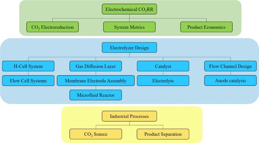
Catalysts 2020, 10, 473 2 of 35

produced chemicals and in most cases can avoid energy intensive steps such as high temperature
condition [6] or additional operations such as enzyme encapsulation [5]. Moreover, the
electrochemical method also demonstrates other benefits, and the most attractive one is being an
alternative in energy storage technology, where it converts intermittent or excessive renewable
energy into stored chemical energy [31]. Another prominent advantage would be the facile
implementation of CO2RR-produced liquid fuels on the existing department of fuel consumption,
such as the transportation sector [32]. This would not be only facilitating the industrial adaption to
renewable fuels but also closing the gap between conventional high-carbon economy and more
sustainable low-carbon industry [33].
 Indicated in Figure 1, the following sections will first introduce the fundamentals on CO2RR
with perspectives from techno-economic analysis. Then the electrolyzer design for CO2RR is
reviewed, with special emphasis on types of electrolyzers and design on individual components in
the reactor. Finally, industrial insights are provided with possible separation methods.

 Figure 1. Study flow chart with sections and subsections.

2. Electrochemical CO2RR

2.1. Carbon Dioxide Electroreduction
 Electroreduction of carbon dioxide is an electrocatalytic process taking place on an
electrocatalyst that is in contact with the cathodic current collector, such as a metal plate or a
conducting support layer. Through a potentiostat or a galvanostat (power source), the electrons
needed for the carbon dioxide molecules to undergo the reduction reaction are provided to the
cathode, whereas the equal number of electrons are simultaneously drawn from the anodic reaction
which is the oxygen evolution reaction (OER) in most cases. An ion exchange membrane is usually
installed in the electrolyzer, dividing the cathodic and anodic chambers. The membrane acts as the
means to selectively allow charge transfer, completing the electric circuit, and at the same time, as a
barrier preventing other products from crossing over.
 Carbon dioxide reduction reaction was discovered by Teeter and Rysselberghe in 1954 [34].
From the late 1960s to the early 1980s, CO2RR was proposed by several research groups toward the
production of mainly formate, oxalate and carbon monoxide [35–38]. Since then, extensive research
on CO2RR has been increasing, and different approaches with various reactor designs have given rise
to multiple renewable chemical products within which some bear the potential to be scaled up and
commercialized. The mechanism of CO2RR in aqueous solutions has been studied profoundly and
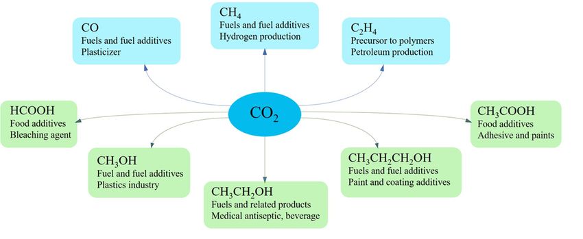
Catalysts 2020, 10, 473 3 of 35

two routes were identified: (1) CO2* (adsorbed molecule) goes through surface hydrogenation and
desorbs as formate ion; (2) CO2* is transformed to CO* and either desorbs as carbon monoxide or
interacts with other adsorbed species and becomes alcohols, hydrocarbons or organic acids [11].
 Among these various CO2RR products reported, the most common ones (Figure 2) are carbon
monoxide (CO), formic acid/formate (HCOOH or HCOO¯), methane (CH4), methanol (CH3OH),
ethylene (C2H4), acetic acid/acetate (CH3COOH or CH3COO¯), ethanol (CH3CH2OH) and 1-propanol
(CH3CH2CH2OH). The electron transfer in each of the mentioned products along with the main
competing reaction, hydrogen evolution reaction (HER), is summarized in Table 1.

 Figure 2. Common products from CO2RR electrocatalysis with their applications.

 Table 1. Summary of common CO2RR and hydrogen evolution reaction (HER), products in alkaline
 solution (pH 14), standard potentials with respect to reversible hydrogen electrode [V vs. RHE] at 1
 atm and 25 °C and the number of electrons transferred [3,39,40].

 Product (phase) Cathode Reaction E° [V vs. RHE] Z
 CO (g) CO2 (g) + 2H2O (l) + 2e− = CO (g) + 2OH− –0.934 2
 HCOO¯ (aq) CO2 (g) + 2H2O (l) + 2e− = CHOO− (aq) + OH− –1.078 2
 CH3OH (l) CO2 (g) + 5H2O (l) + 6e− = CH3OH (l) + 6OH− –0.812 6
 CH4 (g) CO2 (g) + 6H2O (l) + 8e− = CH4 (g) + 8OH− –0.659 8
 C2O42¯ (aq) 2CO2 (g) + 2e− = C2O42− (aq) –0.590 2
 CH3COO¯ (aq) 2CO2 (g) + 5H2O (l) + 8e− = CH3COO− (aq) + 7OH− –0.703 8
 C2H5OH (l) 2CO2 (g) + 9H2O (l) + 12e¯ = CH3CH2OH (l) + 12OH− –0.744 12
 C2H4 (g) 2CO2 (g) + 8H2O (l) + 12e− = C2H4 (g) + 12OH− –0.764 12
 C3H7OH (l) 3CO2 (g) + 13H2O (l) +18e− = CH3CH2CH2OH (l) + 18OH− –0.733 18
 H2 (g) 2H2O (l) + 2e− = H2 (g) + OH− –0.828 2

2.2. System Metrics
 Regardless of the configuration, a viable CO2RR system should satisfy a few performance
metrics concerning the nature of electrochemistry applicable to the reaction. These requirements
include but are not limited to current density, Faradaic efficiency, overpotential, energy efficiency,
catalyst activity and reactor stability.

2.2.1. Current Density
 One of the most important metrics for industry-scale production is the current density, or to be
more specific, the partial current density related to the desired product. This parameter effectively
reflects the reaction rate of a certain product at given conditions, because the number of electrons
transferred in a chemical reaction is proportional to the extent of this reaction (number of moles of
Catalysts 2020, 10, 473 4 of 35

reactant consumed or product formed). A higher current density in an electrochemical system
indicates a higher reactant consumption rate, while a higher partial current density implies a higher
generation rate of the product concerned.

2.2.2. Faradaic Efficiency
 Another critical parameter is the Faradaic efficiency (FE) of the desired product. It is defined as
the electric charge used for the formation of the desired product over the total charge passed between
the electrodes.

 = × 100% (1)

 Where m is the number of moles of the desired product, n is the number of electrons required
per mole of product, F is the Faradaic constant (96485 C/mol electrons) and q (or current × time) is
the total charge passed between the electrodes in an experiment. Since the Faradaic efficiency
represents the selectivity toward a specific product, an improvement on the FE can directly increase
the amount of CO2 converted to the desired product, reduce product separation cost, and eventually
lower the energy penalty of the electrocatalysis.

2.2.3. Overpotential
 The overpotential (η) of an electrochemical reaction is the extra voltage needed compared to the
thermodynamic prediction in order to have this reaction occur in the system. It is generally
categorized into two components: the result of activation polarization (ηactivation) to overcome the
activation energy barrier for reactions to occur on the catalytic electrode surface and the mass transfer
limitation of dissolved CO2 (ηdiffusion) [4,41]. It should be noted that the ohmic drop (iRS) across the
electrolyte and ion exchange membrane would not be accounted for the overpotential but rather a
potential loss that is only dictated by the ionic conductivity of the system when a current is present.

2.2.4. Energy Efficiency
 Combining Faradaic efficiency and overpotential along with other losses, the energy efficiency
(EE) can be derived for each species as well as across the whole cell to indicate the conversion of
applied energy toward chemically stored energy.

 = × (2)
 + +
where E° is the thermodynamic reaction voltage, η is the sum of the overpotentials and iRS represents
the ohmic loss across the cell. The fraction in the equation is also considered as the voltage efficiency.
The energy efficiency is central for the operational cost calculation and therefore becomes the most
important metric for cost analysis. Only with a high Faradaic efficiency and a relatively high voltage
efficiency can the EE of a system be acceptable.

2.2.5. Tafel Parameters
 In a Tafel plot, the overpotential η is usually plotted against the logarithm of current density.

 = + ( ) = −2.303 ( ) + 2.303 ( ) (3)

 From the intercept of the plot, the exchange current density i0 can be obtained, which is the
current density at equilibrium. The exchange current density is known as an indicator of the catalytic
activity and reaction kinetics [42]. The charge transfer coefficient α can be determined from the slope.
The smaller the Tafel slope, the larger the charge transfer and the more active the catalyst. A sudden
change of the slope usually implies the change in reaction mechanisms due to the reaction conditions
such as electrolyte concentration, reactants and catalyst surface morphology [43]. Thus, the Tafel
slope can aid identifying elementary steps and rate determining steps. However, carefully
Catalysts 2020, 10, 473 5 of 35

distinguishing the exchange current and Tafel slopes for each product from CO2RR is required as
different products result from different reaction mechanisms. To further understand this challenge,
it should be noted that the obtained current density may be a summation of multiple partial current
densities for production of multiple CO2RR products. Therefore, calculation of Tafel slope for
products produced at lower overpotential (e.g., CO and formate) is more reliable and accurate
compared to calculation of Tafel slope for products with larger overpotentials (e.g., ethylene and
methane). The latter is mainly challenging due to the contribution of other products in the current
density. The recommended method to calculate Tafel slopes for individual CO2RR products is thus
using the partial current density instead of the total current density, which requires precise
measurement of products at low concentrations. If the total current density is used for Tafel slope
calculation, the attained parameters will just indicate the catalytic activity and kinetics for the CO2RR
in general but not for a particular product. Overall, Tafel slope is an important parameter which can
be acquired by simple electrochemical measurements and helps to understand the reaction
mechanism, which will further allow faster progress in research and better reaction control in
industry.

2.2.6. System Stability
 System stability is the ultimate goal with respect to industrializing the electrolyzer. It is consisted
of the durability of the catalyst and electrode, as well as the conditions of the electrolyte and
membrane. This metric can be measured under chrono-potentiometric tests, where the current is
fixed at a proper level and the resulting potential over the half-cell or full cell is recorded. If the system
is robust and stable, the potential difference should be constant over thousands of hours [44]. It is
obvious that by increasing the length of the stable catalysis, maintenance and the associated costs of
the process can be reduced, which plays an important role in scaling up the reactor.

2.3. Product Economics
 With much effort spent on advancing the novel CO2RR technology and implementing it in the
industry, the production of formic acid and carbon monoxide are currently close to being
commercialized. Studies on these two products have been conducted extensively and, to date, there
are multiple start-ups and even established companies that have committed to providing carbon
solutions and transforming energy sources from fossil fuels to clean electricity.

2.3.1. Industry Requirement
 Similar to any other industrial production, the chemical production rate—or sometimes phrased
throughput—for a reactor is among the top criteria to ensure profitability. This requires a higher
production rate than what is currently displayed in the relative research field. As a heterogeneous
catalyzed electrochemical process, the nature of CO2RR dictates that the production rate can only be
boosted by the following two methods: (1) increasing the total catalyst surface area in the reactor, or,
(2) increase the intrinsic reaction rate, which is indicated by the current density. The former method
is certainly the necessary step for scale-up and long-term reactor design, while the latter is of greater
importance since it incorporates the combined effect of catalyst activity and electrode/electrolyte
engineering.
 In general, the current research on CO2RR is mainly focused on the development of catalysts and
the optimization of their performance. However, one of the major issues is the condition in which the
optimization is carried out. As the commercial scale production requires at least 200 mA/cm2 of
current density [40], the research for novel catalyst should bear in mind that this is the target and
where the performance of such catalyst should be optimized upon. Most often, the profitability of a
carbon dioxide conversion project heavily depends on the production cost. This draws close attention
to the operational cost of the system. The biggest challenge nowadays remains to be the low energy
efficiency. To have an improvement in the energy efficiency, the FE of the system should be high,
while the overpotential of the electrolyzer is kept low. By having a high selectivity (FE), the process
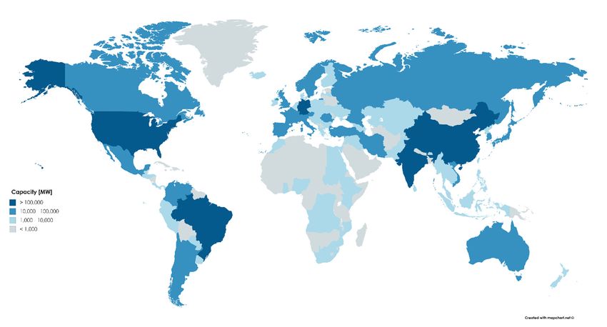
Catalysts 2020, 10, 473 6 of 35

can also reduce separation costs downstream, which can be rather nonlinear depending on the
desired product and its separation technique. Another direct relation to the cost is the duration of
stable operation, which plays a critical role in determining the maintenance cost in a plant. The
minimal stable operation duration required for profitable scaleup should be in the range of 20,000
hours [40,45].

2.3.2. Electricity and Carbon Price Considerations
 The key role of electricity in the profitability of CO2RR has been discussed extensively.
[4,11,40,44,46–48], where reports state that the cost of the electricity is the main factor in operational
expenditure. As a result, locations that have a high cost associated with electricity supply may not be
suitable for such industry and a change in the price can risk the profitability of the whole project.
Furthermore, the source of the electricity is vital. It must be clean and renewable (i.e. solar, wind,
hydro power) in order to realize the carbon neutral goal of the process. This aspect can be satisfied if
the electrolyzer is located in a region with a high capacity of clean sources for electricity or utilized
in a microgrid where the power supply is clean and renewable. As a result, looking at the renewable
energy capacity can greatly help when deciding the plant location. As displayed in Figure 3, the
generation capacity of renewable electricity varies significantly in different regions. For instance, in
2017, North America has 349 GW of total renewable electricity generation capacity, while the Middle
East only has 19 GW of capacity [49]. Higher renewable capacity indicates more opportunity and
larger throughput to realize this carbon neutral mandate.
 With carbon tax or emission trading systems (ETS) starting to be implemented over the globe
(Figure 4 [50]), more attention is paid to lowering of the carbon dioxide emissions from different
economic sectors including oil and gas, transportation, building, heavy industry, agriculture and
others. These policies are set to promote incentives in low-carbon and renewable energy technologies
in order to achieve the climate mitigation goals [51]. Hence, the carbon-neutral power source not only
ensures the carbon objective of the process but can also reduce carbon tax or increase emission trading
capacity in the corporation or local government levels.

 Figure 3. Renewable electricity generation capacity by countries (hydro, marine, wind, solar,
 bioenergy), data source: The International Renewable Energy Agency, IRENA [49].
Catalysts 2020, 10, 473 7 of 35

 Figure 4. Carbon tax or emission trading systems (ETS) current implementation [50].

2.3.3. Feasible Products and Operating Parameters
 One of the analyses that needs to be performed is a techno-economic analysis which would give
a guideline on the feasible products in relation to the required operating parameters. Jouny et al.
considered the end-of-life net present value (NPV) to be the criteria with which some of the most
common CO2RR products are evaluated [40], although other methods that directly compare the cost
of product are used as well [46,47,52]. The end-of-life NPV (in $) can be defined as the summation of
the initial investment (capital expenditure) and the present value of all future cash flows till the end-
of-life of the plant. In short, the NPV takes into account the time value of money and indicates
whether the studied project will be feasible over its lifetime. If NPV is negative, it means the present
value of all future cash flows combined is less than the capital expenditure today, then it is not
considered economically viable unless there are subsidies. The NPV can be calculated as:

 = (4)
 (1 + )

where, CFt is the cash flow ($) in the year t, i is the discount (interest) rate (%) and n is project lifetime
(years) [53,54]. The estimation in such model is based on the material and energy balances for the
process as well as estimated capital and operating expenditures. For a CO2RR plant, the capital
expenditure constitutes mainly of the electrolyzer cost, the cost of product separation equipment,
such as distillation columns and other supporting and auxiliary equipment (balance-of-plant).
Whereas, the operating expenditure is mainly associated with the electricity cost, CO2 acquisition cost
and the cost of maintenance. The variance of the end-of-life NPV of CO2RR products between two
scenarios is shown in Figure 5. In the two distinct scenarios, namely, the base case and the optimistic
case, the current density, cell voltage and conversion are changing variables. Whereas, the production
rate (100 ton/day), lifetime of the plant (20 years), operating time (350 days/year), electricity price
(0.03 $/kWh), CO2 price (40 $/ton), interest rate (10%), product selectivity (90%) and electrolyzer cost
(920$/m2) remain constant [40]. The values of variable parameters for the two cases are taken based
on benchmarks currently feasible and future targets. The values of current density, cell voltage and
conversion for base case are 150 mA/cm2, 2.3V, 30%, respectively, whereas for optimistic case the
values are 300 mA/cm2, 2V, 50%, respectively. From this analysis, the more promising products are
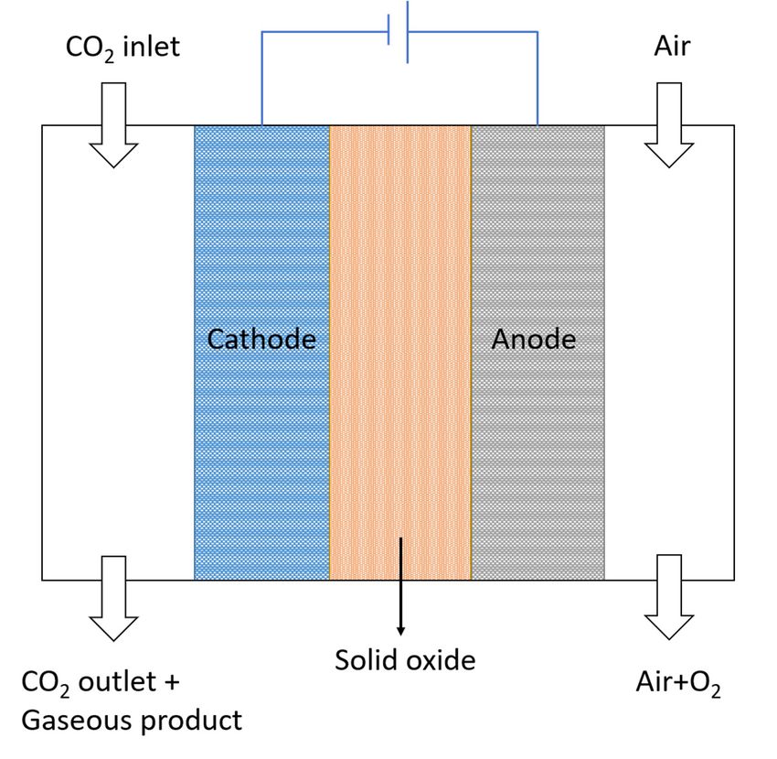
Catalysts 2020, 10, 473 8 of 35

the carbon monoxide, formic acid and propanol, while ethanol and ethylene show feasibility under
optimistic conditions.
 Among the various operating parameters previously discussed as system metrics, sensitivity
analysis on the different CO2 reduction products shows that the selectivity and voltage are the most
important electrolyzer parameters [40]. For the selectivity or FE, to which the current requirement is
inversely proportional, higher selectivity would mean lower energy spent on the by-product(s),
including hydrogen formation, and product separation. This in-turn would reduce the operating
costs greatly. Furthermore, as the current requirement decreases, to maintain the current density, the
electrolyzer area required would also decrease, thus reducing the capital expenditure. For the cell
voltage, it is directly related to the power requirement so lower cell voltage would plummet the
required power and further reducing the operating cost. It should also be noted that current density,
which remains critical to catalyst performance, can be the least significant electrolyzer parameter
beyond a threshold because the electrolyzer capital cost and current density are considered to have
an inverse square relationship [40]. However, the significance of capital expenditure in comparison
to operating expenditure diminishes linearly with time. As a result, it is necessary to achieve a
particular threshold (200–400 mA/cm2) [40]. Increasing the current density beyond the threshold
would have very little impact on the NPV so it is advisable to focus on increasing selectivity or
reducing cell voltage instead.

 Figure 5. Electrolyzer product tornado plots showing end-of-life net present value (NPV) of each
 product with two cases. Adapted with permission [41]. Copyright 2018, American Chemical Society.

3. Electrolyzer Design

3.1. H-cell System
 Traditionally, the electrochemistry takes place in an H-type cell or an H-cell reactor, as illustrated
in Figure 6. In this device, the working electrode, reference electrode and the counter electrode are
fixed by the caps on the two reaction chambers, where the electrolyte is prefilled with no recycle. For
CO2RR, the cathode can be a simple catalyst-deposited carbon substrate such as carbon paper or
glassy carbon electrode. Carbon dioxide gas is purged into the cathode chamber and gas phase
products are collected from the headspace. This type of setup is easy to operate and clean and it is
used to quickly screen various catalysts. Although some successful works were carried out using this
configuration [55], generally it is not suitable for scale-up because of the low solubility of the carbon
dioxide gas in aqueous electrolyte, yielding a limited current density (often < 45 mA/cm2) [56–58].
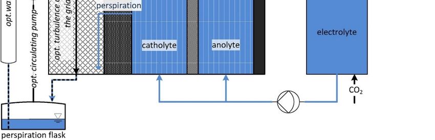
Catalysts 2020, 10, 473 9 of 35

Therefore, to meet the industry requirement, a better setup that enables higher current density and
energy efficiency should be used.

3.2. Flow Cell Systems
 Inspired by the water splitting electrolyzer design, flow cell systems are developed and
investigated in this application. Up to date, there are structurally three types of electrochemical flow
cell systems for a CO2RR reactor: the gas phase electrolyzer, the solid phase electrolyzer and the most
common liquid phase electrolyzer.

3.2.1. Gas Phase Electrolyzer
 In the gas phase electrolyzer (see Figure 7), the catalyst-deposited cathode is fixed with the ion
exchange membrane, forming a structure called membrane-electrode assembly (MEA). The
membrane is usually a solid polymer electrolyte that can transport ionic charges from or to the
cathode, enabling continuous and stable charge transfer in the circuit. This requires the cathode CO2
feed to be humidified or anolyte immediately next to the MEA to be aqueous, providing water to the
cathode catalyst that allows the carbon dioxide reduction to take place. The membrane for a gas phase
electrolyzer can be cation exchange membrane (CEM), anion exchange membrane (AEM) or bipolar
membrane (BPM). In the case of a CEM, protons are transported from the anolyte to the cathode
catalytic sites, whereas an AEM transports hydroxide (OH⁻, as the result of water electrolysis) from
the cathode to the anode. A BPM combines the two types of membrane, so it simultaneously provides
H⁺ to the cathode and OH⁻ to the anode. Some successful experimental results using the gas phase
electrolyzer without flowing catholyte have shown improved partial current density, higher stability
and better control on liquid product concentration for formate production [59] or higher selectivity
on CO production [60,61]. It has also been demonstrated that alcohols [62–64] and other multi-carbon
products [63,65,66] can be selectively produced in a gas phase electrolyzer using membrane-coated
electrodes or MEAs even though the current density is low.

3.2.2. Solid Phase Electrolyzer
 In the solid phase electrolyzer (Figure 8), both electrodes and the electrolyte in between are in
solid form, the latter usually being a layer of solid oxide. The use of high temperature (300–600 °C) is
necessary to activate CO2 reduction [67]. In typical setups, the solid electrolytes can be either oxygen-
ion conducting or proton conducting. In the former case, an oxygen ionic conductor is used. It
transports the oxygen ions formed in the cathode, where water molecules are reduced, to the anode
where oxygen ions are oxidized to oxygen gas. Meanwhile, CO2 molecules on the cathode surface
become reduced by the activated hydrogen. In the proton conducting type solid electrolyzer, the
water molecules are oxidized in the anode, producing oxygen gas and protons that get passed
through the protonic conductor layer and react with CO2 molecules [67]. The main benefit of the
utilization of a solid phase electrolyzer is the high current density due to the enhanced kinetics at
high temperatures [68]. It can also avoid the mass transfer issue of dissolved CO2 in most liquid phase
electrolyzers [67]. However, there are several drawbacks due to high temperature, including the
challenge in proper sealing, CO as the only reduced carbon product, carbon deposition, metal
particles oxidation, low current efficiency and cell degradation [67,69], which require more
sophisticated research before this is accepted in the industry.

3.2.3. Liquid Phase Electrolyzer
 Most commonly used in the electrocatalysis of carbon dioxide is the liquid phase electrolyzer, as
shown in Figure 9. The main characteristics of this type of reactor are the presence of liquid electrolyte
in both electrodes, commonly with a gas diffusion layer (GDL) on both electrodes and an ion
exchange membrane in the electrolyte bulk. Similar to the gas phase electrolyzer, the membrane
serves the purpose to transport ionic charges between the electrodes. Depending on the types of the
membrane (CEM, AEM or BPM), the corresponding charged ions are passed to the electrolyte and
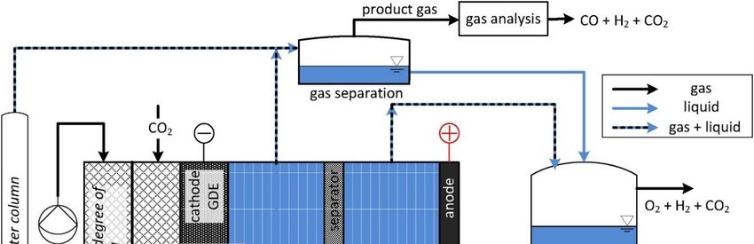
Catalysts 2020, 10, 473 10 of 35

therefore complete the circuit. The distinctive feature in this kind of system from the earlier
mentioned gas phase electrolyzer is the possibility to engineer flowing catholyte. As a result of the
presence of the liquid catholyte, CO2 inlet to the cell does not need to be humidified and can be
utilized in a pressurized setting [70].

 Figure 6. H-cell configuration.

 Figure 7. Gas phase electrolyzer with membrane-electrode assembly (MEA).
Catalysts 2020, 10, 473 11 of 35

 Figure 8. Solid phase electrolyzer.

 Figure 9. Liquid phase electrolyzer.

3.3. Gas Diffusion Layer
 Gas diffusion layer (GDL) was developed historically for fuel cells [71–73] and water
electrolyzers [45,74], and it is a means to provide triple phase boundary of carbon dioxide gas, catalyst
surface and electrolyte [45]. However, it was shown that without the presence of water content, the
reaction conversion is poor [75–78]. Further studies have proposed that due to the wetting
characteristics of the catalytic surface under negative potentials [79], CO2RR is still occurring in the
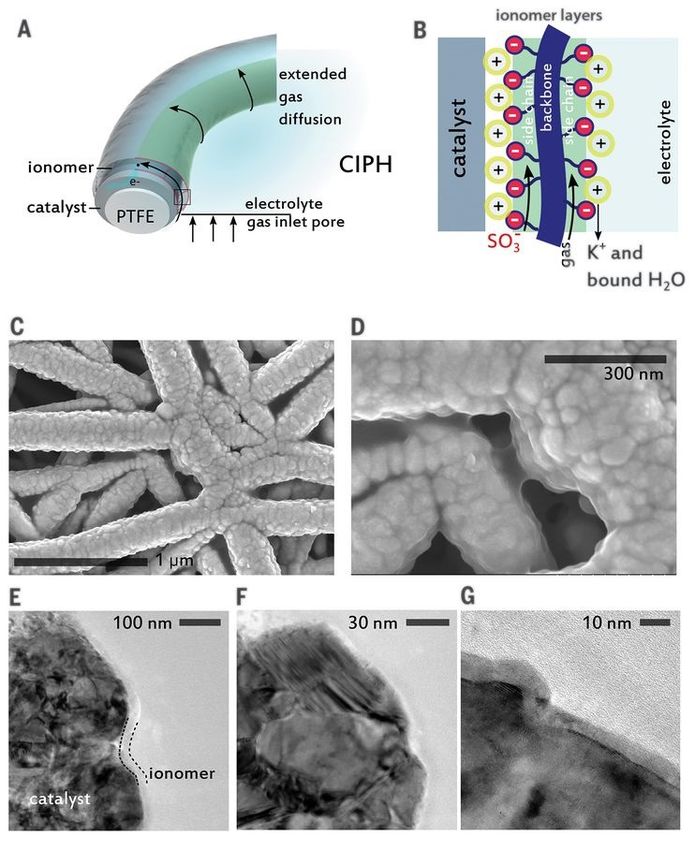
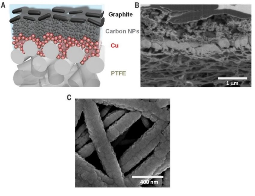
Catalysts 2020, 10, 473 12 of 35

aqueous phase with CO2 in dissolved fashion [57,80]. This postulate should be more closely examined
with computational revelation and in situ experimental confirmation.
 In a typical H-cell setup, prior to the electrochemical experiment, carbon dioxide needs to be
dissolved from gas purging in the bulk electrolyte until the solution is saturated [81]. When CO2RR
occurs, all products are leaving the surface in the opposite direction of incoming dissolved CO2. On
the contrary, in the case of a gas diffusion electrode (GDE) with a GDL, the liquid products remain
in the aqueous phase due to the hydrophobicity of the GDL, and only the gaseous products leave
from the gas side of the surface. Compared to the traditional H-cell configuration, the main benefits
of the use of a gas diffusion layer on the electrode are linked to its better mass transfer characteristics
and shorter diffusion path [82]. It was discovered that the diffusion path for dissolved CO2 from the
bulk to a non-permeable catalytic electrode surface is in the proximity of 50 microns whereas the
diffusion distance from the gaseous CO2 to the liquid surrounded catalyst surface is only about 50
nanometers [57,80]. Due to this unique phenomenon, two significant benefits arise. First, the shorter
diffusion path ensures the CO2-saturated electrolyte layer on the catalyst, which was shown to
prevent HER [83]. Second, the CO2 gas can get to the active sites much faster before it gets reacted
with the hydroxide in the electrolyte, hence allowing the use of alkaline electrolytes [84].
 Another unique characteristic of GDL is the reaction direction of carbon dioxide. On an H-cell
electrode, the CO2 is approaching the catalyst surface from the bulk while on a GDL, the reactant gas
is purged through the hydrophobic layer on the support, which prevents the gaseous products
agglomerating and blocking catalyst surface and in the meantime facilitates the adsorption of
incoming CO2 [85]. Therefore, the implementation of a GDL simultaneously solves the issues of mass
transfer limitations and the availability of CO2 at the liquid-catalyst interface. As a result of the
improved CO2 concentration at the surface of the catalyst, the designed morphology and surface area
of the catalyst can result in better activity, lower overall cell potentials and perform more closely to
the research intention [85]. Due to these important benefits, the use of gas diffusion layer is strongly
recommended if the process is to be scaled up in this setup [32,57,85,86].
 There are also challenges related to the GDL in electrolysis, especially at a high current density.
It is subject to potential crystallization of hydroxide and bicarbonate salts in the porous layer of the
GDL, because of the increase hydroxide formation on cathode [85]. At current densities higher than
50 mA/cm2, the local pH is shifted to 12 and above, resulting in a different local environment for
CO2RR as opposed to the bulk, which needs to be properly addressed such that the catalyst designed
is not optimized under unexpected reaction conditions [57,85]. In operation aspects, several points
should be noted. First of all, the ohmic loss iRS will be higher because the current is higher. In
addition, the electrolyte pH, temperature of the electrodes and charge conductivity may be changed
overtime due to concentration polarization between the two electrodes [85]. In addition, the pressure
between the two phases is crucial in reaction local environment as well. To maintain the ideally
wetted surface on the catalyst remains one of the most practical challenges for CO2 electrolyzers,
which is also known as water management on the GDE [87].
 Due to the nanostructure of the hydrophobic layer, contaminants in the electrolyte are
detrimental to the active sites on the catalyst surface, precautions and protection of the electrode
should be carefully considered when GDE is used. To overcome the instability of GDE, Dinh et al.
have reported a robust design where the catalyst is sputtered on a porous layer of PTFE and
nanoparticle carbon is spray-coated on top of the catalyst layer, stabilizing the copper catalytic layer
in potassium hydroxide (KOH) solution (Figure 10) [82,84]. García de Arquer and coworkers recently
achieved a partial current density of 1.3 A/cm2 toward ethylene production using just a thin film of
Nafion® ionomer on the catalyst without any carbon or graphene layers, which they called
catalyst:ionomer bulk heterojunction (Figure 11) [88]. Such architecture, according to the authors, can
extend the CO2 gas diffusion zone along the catalyst surface, thus promotes more CO2 conversion
and higher current density.
Catalysts 2020, 10, 473 13 of 35

 Figure 10. Structure of the polymer-based gas diffusion electrode. (A) Schematic illustration of the
 graphite/carbon NPs/Cu/PTFE electrode. PTFE is polytetrafluoroethylene polymer. (B) Cross-
 sectional scanning electron microscopy (SEM) image of a fabricated graphite/carbon NPs/Cu/PTFE
 electrode. (C) SEM image of Cu nanoparticles sputtered on the PTFE membrane. Reused with
 permission [84]. Copyright 2018, The American Association for the Advancement of Science.
Catalysts 2020, 10, 473 14 of 35

 Figure 11. Catayst:ionomer planar heterojunction design. (A) Schematic of metal catalyst deposited
 onto a polytetrafluoroethylene (PTFE) hydrophobic fiber support. A flat ionomer layer conformally
 coats the metal. (B) Perfluorinated ionomers such as Nafion exhibit differentiated hydrophilic and
 hydrophobic characteristics endowed by –SO3– and –CF2 functionalities, respectively. (C,D) Scanning
 electron microscopy (SEM) images of ionomer-coated copper catalysts. (E–G) Cryo-microtomed
 transmission electron microscopy (TEM) cross-sections of catalyst and ionomer revealing a laminar
 conformal overcoating. Reused with permission [88]. Copyright 2020, The American Association for
 the Advancement of Science.

3.4. Membrane Electrode Assembly
 With many limitations in traditional H-cell configuration, gas phase electrolyzers were also
developed to account for better mass transfer and lower cell potential. Similar to liquid phase
electrolyzers, the reaction takes place in the three-phase region on the catalyst rather than the liquid
bulk. This again ensures a sufficient concentration of carbon dioxide at the catalytic surface. What
differentiates an MEA type of electrolyzer from a GDE liquid phase electrolyzer is the lack of liquid
electrolyte in the cathode. As shown in Figure 7, the membrane is placed or even bound directly on
the electrode. The other side of the electrode is then covered by a layer of gas diffusion porous
medium.
Catalysts 2020, 10, 473 15 of 35

 The most common type of membrane used in the MEA setup is the proton exchange membrane
with a perfluorosulfonic acid (PFSA) basis such as Nafion® [59,63–66,75,77], which transports protons
from the electrolyte in the counter electrode to the adsorbed CO2 molecules. Studies also show
promising results using AEM in the assembly [60,89–91], where membranes with imidazolium on
styrene backbone can both increase the CO selectivity and current density with considerable
durability [60]. Li et al. [92] have shown that by using a bipolar membrane in the MEA, pH control
on both electrodes can be realized, while current density, overpotential and stability are also achieved
with a better standard than other membranes.
 A typical electrolyzer structural design using MEA consists of an anode chamber with liquid
phase anolyte and a cathode chamber with only gas phase inlet. An alternative type of electrolyzer
has also been developed in which the anode and cathode are both electrolyte-free. In this electrolyte-
free (or “zero-gap”) setting, the anode feed is humidified hydrogen gas [77,89].
 MEA excels at reducing the use of flowing electrolyte thus lowering ohmic loss while the GDE
eliminates the concentration polarization in the bulk electrolyte which occurs in H-cells. It also avoids
the high temperature startup and operation required in a solid electrolyzer. However, there are also
challenges to be overcome. The first problem in MEA setup is the water management on the cathode
catalysis surface. One simple way to solve this is to use properly humidified CO2 as the feed.
However, even with the humidification, membrane can turn dry in an experiment, so anolyte is still
needed to ensure water supply to the cathode catalyst [60]. In addition, the liquid products generated
by CO2RR face the challenge to be separated and collected on the industrial scale. This is because
most often the liquid products are collected from the cold trap on the cathode outlet [63,65,66,75,90].
In this fashion, the liquid production is hardly constant over time and thus can only be processed in
a batch mode. Another issue associated with the liquid products is the crossover from cathode and
re-oxidation at anode. In many assemblies with AEM or even Nafion®, charged aqueous products
such as formate, acetate and small molecules like methanol can be easily transported from cathode
to anode [93]. Then at anodic OER potential, these products can be oxidized which would release CO2
back to the atmosphere [78,91].
 In summary, using a membrane electrode assembly in a CO2RR electrolyzer can benefit from
lowered material costs, reduced cell potential as well as enhanced CO2 mass transfer. Challenges in
such setup remain in aspects including water management on cathode surface, scale-up difficulties
in liquid product collection and crossover of liquid products to the anode.

3.5. Microfluidic Reactor
 To further decrease the cell potential while alleviating mass transfer limitation, membrane-less
electrolyzers with GDL were developed and stand as an alternative in commercializing CO2RR. This
type of electrolyzer is called the microfluidic reactor, emphasizing the thin layer of electrolyte
between cathode and anode. This setup exploits the benefit of laminar flow of the electrolyte which
then can reduce mixing and thereby neglecting the use of membrane in the cell [94,95]. The design of
the flowing electrolyte allows tailoring of the pH and temperature of the reaction environment which
would be considered limited by the presence of membrane [96,97]. This feature also enables
continuous liquid product sampling and analysis just like other liquid phase flow cells [96].
 Challenges related to the microfluidic reactors reside in the design of electrolyte flow. If the
electrolyte is flowing in one channel, there can be crossover from cathode to anode which will result
in oxidation of formic acid, methanol or other liquid products. To mitigate this problem, some design
can be considered when utilizing such electrolyzers, including nanoporous separator or multichannel
design [98] and dual-electrolyte system [94]. These modifications, or variations of microfluidic cells
face an important issue of diffusion constraint in the liquid phase due to the absence of a semi-
permeable membrane. After a certain length along the flow axis, the diffusion zone for the cathodic
product layer gets wider and will eventually meet the anode GDL. This certainly depends on the flow
rate and the specific channel design, but with a minuscule flow depth, it yields a small characteristic
length in diffusion direction, giving rise to difficulty in scaleup of the reactor.
Catalysts 2020, 10, 473 16 of 35

 Up to this point, a brief summary on the structural design of CO2RR electrolyzers is shown in
Figure 12.

 Figure 12. Electrolyzer types summary with advantages and disadvantages highlighted.

3.6. Catalyst
 In any CO2RR reactor, catalyst plays a critical role when certain groups of products are being
targeted. Common catalysts include metal-based catalysts such as Cu, Au, Ag, Sn, Bi and non-metal
elements such as graphene and carbon nanotube (CNT). The selection of catalyst directly defines the
possible reaction pathway and intermediate energy states. Generally, catalysts can be deposited,
spray-coated, drop-casted, electrodeposited onto a substrate or directly used as the electrode in the
case of an H-cell.

3.6.1. CO Production
 Since CO is the simplest gaseous product from CO2 reduction with only two electrons
transferred, the process has been heavily studied and several elements have been reported to have
superb selectivity toward the diatomic molecule. It is noticed that gold, silver and sometimes bismuth
are excellent at converting CO2 to CO with high selectivity. AuFe core-shell nanoparticles have shown
a mass activity of 48.2 mA/mg for CO production along with near unity selectivity and 90 h stability
[99]. Size-dependent catalytic activity was also studied on micelle-synthesized Au nanoparticles and
a drastic increase in activity was found in size range below 2 nm for electroreduction of CO2 to CO
[100]. More commonly, Ag is used as the catalyst for CO2 to CO conversion and there are various
methods in synthesis of the catalyst or electrode material. For Ag nanoparticles, when switch from
conventional carbon support to TiO2 support, Faradaic efficiency of 90% and current density of 101
mA/cm2 can be reached [101]. By incorporating a mixed layer of multi-walled carbon nanotubes and
the Ag catalyst, the charge transfer resistance can be decreased, resulting in a much-improved current
density (350 mA/cm2 at −0.8 VRHE) [102]. Organometallic silver catalysts have also been developed to
demonstrate 90% selectivity and 95 mA/cm2 current density [103]. Dinh et al. fabricated their silver
catalyst by using a sputtering system and adding a carbon nanoparticle layer, which then showed an
overall performance in CO production with over 90% FE, 150 mA/cm2 and for over 100 h of operation
[82]. Some recent research has presented novel Ag-GDE catalyst by direct synthesis through metal-
organic framework (MOF)-mediated approach, which can maximize the metal catalyst activity
toward 1864 mA/mgAg (silver loading of 0.2 mg/cm2 and CO partial current density of 385 mA/cm2)
[104]. In addition to the common Au and Ag related precious metals, Bi-based material in
combination with ionic liquids can also catalyze CO production from CO2 with EE of ~80% or
Catalysts 2020, 10, 473 17 of 35

selectivity of 85%–87% [105,106]. Recent studies also demonstrated the possibility of CO production
via non-precious metals such as Bi, Pb, Sn and Ni [107,108]. One of the most impressive studies from
Kutz and coworkers shows the possibility of using Ag nanoparticles in an MEA to convert CO2 to CO
at 200 mA/cm2 with 1000 h stability [60].
 In summary, CO as a CO2RR product has undergone a massive amount of research where most
promising results are from the utilization of gold and silver, while a transition toward earth-abundant
metals has also been seen recently. In spite of the achievement in CO production, challenges remain.
Zhao and coworkers have pointed out that surface engineering and morphology control is critical in
improving the Faradaic efficiency and minimizing the overpotential [109]. Referring to the industry
requirement of 200 mA/cm2 current density, even though CO is the product closest to
commercialization, more stability experiments at the relevant conditions on different catalysts and a
thorough life cycle analysis (LCA) are still lacking. Therefore, future work should focus on the design
and control of the catalyst surface for production of carbon monoxide while understanding the effect
of solvent molecules interaction at the interface under high current is equally important.

3.6.2. Formic Acid Production
 Formic acid is an interesting chemical product that is widely consumed by the animal feed
industry and textile industry, with a global market nearing 878.7 million U.S. dollars [110]. Compared
to multi-carbon products, the formation of formic acid is relatively straight-forward, and p-block
metals are common catalysts for this reaction [111–114]. Among these catalysts, Bi has garnered
interest due to its low toxicity, relative availability and high selectivity towards formate production.
According to DFT studies, Bi electrode surfaces have demonstrably higher free energies of hydrogen
adsorption, thus leading to decreases in HER catalytic activities hence higher CHOO− selectivity [115].
The excellent properties of Bi electrodes have been demonstrated in many past works: Han et al. had
synthesized Bi nanosheet electrodes with F.E. close to 100% at −1.3V vs. SCE [116]; meanwhile, work
from Wang et al. with bismuth oxyiodides has demonstrated high current densities (40 mA/cm2) at
−0.9V vs. RHE while maintaining high FE [117]. The continued development of Bi-based catalysts is
ongoing and the adoption of some catalyst fabrication techniques to Bi may be promising.
 It is widely recognized that the use of alloys, instead of pure metal catalysts can better tune the
catalyst’s surface electronics, thus optimizing the catalytic properties; this method has been adopted
for the combination of many p-block metals with each other or with transition metals. For example,
Sn/Pb alloy has been demonstrated to have 79.8% FE toward formate [118], while Sn/Cu alloys have
reached 95% FE [81]. There have been studies conducted on noble metal catalysts such as Sn/Au alloy,
but its Faradaic efficiency and overpotential were inferior to many non-noble metals counterparts
previously reported [119]. The prospect of using noble metal catalyst becomes more enticing when
low overpotential can be achieved, such as a Pd nanoparticle catalyst reported to reach 97% FE at
−0.2V vs. RHE [120]. However, from the same study, it was shown that Pd catalysts are prone to CO
poisoning, which limits the stability of the system. Attempts have been made to mitigate Pd
instability through surface modifications, but the results do not satisfy the range of preferred stability
recommending in techno-economic analyses, generally in hundreds of hours. There have also been
forays into non-metallic materials in the search of a more stable catalyst, such as boron-doped
diamond catalyst which has shown promising FE ~90% for a period of 24 h, but the reported current
density is lower than Sn or Pb electrodes [121].
 Alternatively, another promising group of catalysts combine carbon support along with p-block
metal to form the catalyst. For example, a class of nanocrystalline carbon support called graphene
nano-flakes (GNF) has been previously developed, which exhibits stability enhancement effects and
can be functionalized and decorated with nanoparticles [122]. Previous studies have experimented
with combining this material with copper nanoparticles, producing a catalyst that produces formate,
albeit at low selectivity. But ongoing investigations are exploring the prospect of using p-block metals
and other metal oxide, sulfide compositions.
Catalysts 2020, 10, 473 18 of 35

3.6.3. Multi-Carbon Production
 Cu is a unique catalyst for CO2RR reaction. It has the potential to produce 16 products [123],
including many multi-carbon products [124–126]. Cu surface modification remains an active area of
research. Techniques including oxide derived (OD) Cu, electrodeposition, nanoparticle (NP)
deposition, bimetallic combination, etc. were tested in the past few years to tune the selectivity,
improve current density and stability. Stability is also an important test parameter when a new
catalyst is developed. Cu alloys with Zn, Cd, Ag, Sn, Pb, Ni, Bi, Pd, etc. were synthesized to stabilize
the Cu NPs and tune the CO2 RR product species [127]. The bimetallic structure can be applied to
both H-cells and flow cells. More tests with bimetallic catalysts can be run to discover the effect of
alloy structure.
 OD Cu foils are often tested in the H-cell setup. Metals such as Au and stainless steel are used
as the support for electrodeposition to create various nanostructures like nanofoams and nanocrystals
[128]. These substrates not only provide conductivity to complete the circuit, but also have the
advantage that deposition potential on a foreign substrate is often higher than that on the same metal
because of the crystallographic substrate-metal misfit. [129] However, it is still hard to reach a current
density higher than 45 mA/cm2 in H-cells, so H-cells are only suitable for lab scale research. While in
liquid phase flow cells, various GDL were used for Cu particle deposition, some based on carbon
fibers such as Sigracet® and Freudenberg® and other based on hydrophobic polymers such
polytetrafluoroethylene (PTFE). The catalyst layer should also be porous to allow access to CO2 flow
from one side and electrolyte from the other side, instead of the planar geometry in H-cells. The Cu
catalysts on the GDL have better access to CO2 due to more surface area and short gas diffusion
distance, which contribute to higher current density [130]. More effort should be spent on developing
catalysts in the flow cell since it has the potential to achieve the desired current density for
commercial scale production. The higher local pH value in flow cells as mentioned before, could help
the performance of CO2RR. However, the accumulation of OH− near the catalyst could form crystals
such as Cu(OH)2 and change the catalyst performance.
 Beside Cu-based catalysts, various experiments also shed light on the possibility to produce C2+
with non-metal catalysts such as B-N-co-doped carbon structures [131], graphene quantum dots
[132,133], Cu-based metal-organic frameworks [134] and carbon nanotubes [65]. However, most
surface modification methods, including metallic or carbon-based structures, are very energy
intensive. Further LCA should be done on the catalyst to ensure the whole process is carbon negative
or at least carbon neutral. A balance needs to be found in the future between catalyst performance
and energy consumption during the synthesis process.

3.7. Electrolyte
 The impact of the electrolyte is generally well understood thanks to the previous
electrochemistry advancement. The general requirement for a feasible electrolyte can be summarized
to the three properties that it should bear: good ionic conductivity, stable pH in bulk and moderate
to high CO2 solubility [85]. Two distinct types of electrolyte have been developed by now, which are
the aqueous electrolytes and ionic liquids [135]. The most common aqueous electrolytes in the
research realm nowadays are families of sulfates [136], chlorides [137], bicarbonates [75,91] and
hydroxides [70,83]. In more detailed study on the hydration effects, bicarbonates and hydroxides
which create an alkaline environment are shown to be better suited in production of CO [82], formate
[136] and C2+ products [84,138,139].

3.7.1. Alkaline Solution
 One of the most common electrolytes is alkaline solution, after it was discovered to bear lower
overpotential than its neutral counterpart [57,140]. Its high alkalinity in electrolyte is shown to be
suppressive on HER and thus beneficial toward multiple CO2RR products [70,82,84]. Specifically, in
alkaline conditions, without many protons available to the catalyst surface, the hydrogen evolution
Catalysts 2020, 10, 473 19 of 35

reaction is sufficiently limited, whereas CO2 is open to more active sites, therefore lowering applied
potential and improving Faradaic efficiency [70,140–143].
 In production of CO from CO2, it was reported by Verma and coworkers that the use of 2 M
KOH as electrolyte can promote activity of CO2RR, reaching a partial current density of 99 mA/cm2
toward CO with a cathode overpotential of 0.02V [144]. Elevated concentration of KOH has also been
investigated and its positive effect on product yield was also discussed [70,141]. It was demonstrated
by Verma et al. that the anion effect of hydroxide on the double layer formed on the electrode surface
can lead to better stability of CO2RR intermediates and reduce the likelihood of HER compared to
bicarbonate and chloride [141]. By adding traces of halides to the electrolyte, experiments have shown
that these anions can improve CO selectivity, modify surface morphology and promote protonation
of the adsorbed species [145]. With this technique, current density of ethylene production is largely
increased [84].
 Another electrolyte, potassium bicarbonate (KHCO3), is widely used in this field of study
because of its CO2 affinity and inexpensiveness [38,146,147]. However, lower conductivity of KHCO3
solutions can be a shortcoming which leads to higher cell potential or lower current density,
compromising the energy efficiency of the electrocatalysis [11,141,148]. Moreover, a disadvantage for
buffer solutions such as KHCO3 is the favor of proton transport, which as a result promotes H2 and
CH4 formation instead of C2+ products such as ethylene [149–151]. Verma et al. also found smaller
overpotentials and lower impedance using KOH versus KHCO3 as electrolytes for CO production
[141].
 Different choices for electrolyte are considered to be determinant due to also some hydrated
cations effects known to the CO2RR process [152,153]. The cation effect is studied, and evidence shows
the preference to CO production on silver surface is facilitated by larger cations such as K+, Ru+ and
Cs+ [154]. Recent density functional theory (DFT) computation-guided experimental results show that
the lack of hydronium near Ag catalytic surface can promote formate yield if the electrolyte is overall
alkaline [83]. From CO2RR to ethylene on Cu electrocatalyst, the same overpotential shift toward
more positive values with the use of concentrated KOH is again observed [84].
 However, there is a persisting issue of CO2 uptake because of the hydroxide reacting with the
dissolved carbon dioxide [155], which changes the electrolyte content and conductivity overtime thus
jeopardizes the electrode durability. To realize the goal of stable and sustainable operation,
engineering solutions are urgently needed. Challenges accompanied with the high local
concentration of OH- include the surface reconstruction that allows irreversible binding of CObridge
that is unreactive under reduction potentials [156], as well as water management [87] and mass and
charge transfer modeling at the gas-catalyst-electrolyte interface [157,158].

3.7.2. Pressure and Temperature Effects
 Generally higher pressure of the operating electrolyzer can help increase the adsorption of CO2
species on the catalytic surface because of the increased concentration of CO2 in the gas channel and
in the liquid electrolyte. Earlier works have shown an increase in current density by increasing CO2
partial pressure on Co, Fe, Cu, Pb, Hg, In and other catalysts [159,160]. Dufek and coworkers
experimented at 18.5 atm and 90 °C where they observed lowered cell potential (below 3.0 V) at
applied current density of 225 mA/cm2 with above 80% FE toward CO on Ag-based catalyst and 50%
EE [161]. According to Gabardo et al., a pressurized (7 atm) flow cell reactor combined with the use
of high concentration KOH solution (7 M) as electrolyte can greatly improve the half-cell energy
efficiency to 81.5% at an industry-relevant current density of 300 mA/cm2 [70]. However, the water
management and GDL maintenance should be carefully handled in higher pressure systems.
Unbalanced pressure across the GDL can result in either flooding of the catholyte or drying of the
catalyst surface which can prevent the cell from normal operation [162].
 For a liquid phase system, most of the studies using a GDE were conducted at ambient
temperature, and the effect of temperature on the reaction has rarely been studied. Löwe et al. have
shown that the optimal temperature in alkaline condition (pH = 10) for formate production on tin
oxide loaded GDE was 50 °C [86]. It was reported to be the balance of electrode activity and the
You can also read