Fault zone architecture of a large plate-bounding strike-slip fault: a case study from the Alpine Fault, New Zealand - Solid Earth
←
→
Page content transcription
If your browser does not render page correctly, please read the page content below
Solid Earth, 11, 95–124, 2020
https://doi.org/10.5194/se-11-95-2020
© Author(s) 2020. This work is distributed under
the Creative Commons Attribution 4.0 License.

Fault zone architecture of a large plate-bounding strike-slip fault:
a case study from the Alpine Fault, New Zealand
Bernhard Schuck1,a , Anja M. Schleicher2 , Christoph Janssen1 , Virginia G. Toy3,a , and Georg Dresen1,4
1 Helmholtz  Centre Potsdam, GFZ German Research Centre for Geosciences,
Section 4.2: Geomechanics and Scientific Drilling, Potsdam, Germany
2 Helmholtz Centre Potsdam, GFZ German Research Centre for Geosciences,

Section 3.1: Inorganic and Isotope Geochemistry, Potsdam, Germany
3 Department of Geology, University of Otago, Dunedin, New Zealand
4 University of Potsdam, Institute of Geosciences, Potsdam, Germany
a now at: Johannes Gutenberg-Universität Mainz, Tectonics and Structural Geology, Mainz, Germany

Correspondence: Bernhard Schuck (bernhard.schuck@gfz-potsdam.de)

Received: 10 June 2019 – Discussion started: 17 June 2019
Revised: 8 November 2019 – Accepted: 19 November 2019 – Published: 22 January 2020

Abstract. New Zealand’s Alpine Fault is a large, plate-             2007; Peacock et al., 2016). The structure, composition,
bounding strike-slip fault, which ruptures in large (Mw > 8)        hydrological properties and seismo-mechanical behavior of
earthquakes. We conducted field and laboratory analyses of          faults are typically intimately related. These interactions also
fault rocks to assess its fault zone architecture. Results reveal   govern strain distribution and depend on various factors, such
that the Alpine Fault Zone has a complex geometry, com-             as lithology (Faulkner et al., 2003; Schleicher et al., 2010;
prising an anastomosing network of multiple slip planes that        Holdsworth et al., 2011; Rybacki et al., 2011), fluid pres-
have accommodated different amounts of displacement. This           sure (Hickman et al., 1995; Janssen et al., 1998; Fagereng
contrasts with the previous perception of the Alpine Fault          et al., 2010), stress field and stress magnitudes (Sibson, 1985;
Zone, which assumes a single principal slip zone accommo-           Faulkner et al., 2006; Lindsey et al., 2014).
dated all displacement. This interpretation is supported by re-        Faults control the strength of the Earth’s lithosphere (Tow-
sults of drilling projects and geophysical investigations. Fur-     nend and Zoback, 2000; Bürgman and Dresen, 2008) and
thermore, observations presented here show that the young,          govern substantially fluid flow (Caine et al., 1996; Wib-
largely unconsolidated sediments that constitute the footwall       berley et al., 2008). Hydrocarbon production from fault-
at shallow depths have a significant influence on fault gouge       compartmentalized reservoirs (Van Eijs et al., 2006), ex-
rheological properties and structure.                               ploitation of fault-hosted mineral deposits (Cox et al., 1986)
                                                                    and long-term integrity of potential nuclear waste reposito-
                                                                    ries (Laurich et al., 2018) are practical examples demonstrat-
                                                                    ing how important it is to understand fault zone properties
1   Introduction
                                                                    and their spatial and temporal evolution. Furthermore, large,
A fault, a planar discontinuity in rock where one side has          plate-bounding strike-slip faults such as the Alpine Fault
moved relative to the other parallel to the discontinuity plane,    (New Zealand), the North Anatolian Fault Zone (Turkey)
constitutes a rheological and mechanical manifestation of lo-       and the San Andreas Fault (USA) rupture in large (Mw > 7)
calized deformation (Twiss and Moores, 2007; Ben-Zion,              earthquakes (Toppozada et al., 2002; Sutherland et al., 2007;
2008; Fossen, 2016; Fossen and Cavalcante, 2017). Large             Bohnhoff et al., 2016). Many of these faults are located in
fault zones are typically composed of networks of smaller,          densely populated areas so they pose a significant geohazard
individual, but related and interacting, faults of self-similar     (Eguchi et al., 1998; Sahin and Tari, 2000; Martínez-Garzón
geometry (Ben-Zion and Sammis, 2003; Twiss and Moores,              et al., 2015). Thus, from a georesource, seismic hazard and

Published by Copernicus Publications on behalf of the European Geosciences Union.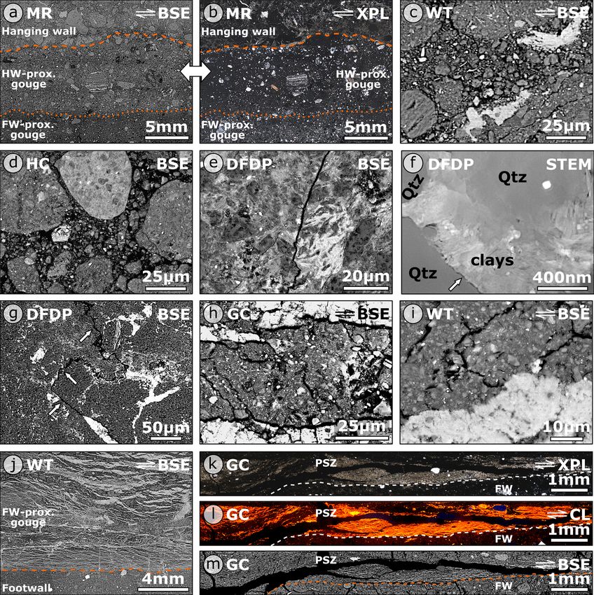
96                                         B. Schuck et al.: Fault zone architecture of a large plate-bounding strike-slip fault

                                                                          The Punchbowl Fault, an inactive, exhumed part of the
                                                                       San Andreas Fault system, typifies this conceptual model of
                                                                       fault zone architecture. It has a single PSZ embedded in a
                                                                       fault core and the surrounding damage zone. A single, con-
                                                                       tinuous gouge layer with 30 cm thickness on average hosts
                                                                       the ∼ 1 mm thick PSZ. The core of the Punchbowl Fault
                                                                       is surrounded by an approximately 15 m thick damage zone
                                                                       (Chester and Logan, 1986; Chester et al., 2005).
                                                                          However, other faults show a more complex structure with
                                                                       changing properties along strike or down dip (e.g., Wibber-
                                                                       ley et al., 2008; Faulkner et al., 2010). For example, detailed
                                                                       studies of the Carboneras Fault, Spain, yielded a conceptual
                                                                       model that is suitable for broader, typically phyllosilicate-
                                                                       rich fault zones, which tend to contain multiple high-strain
                                                                       zones (Fig. 1b; Faulkner et al., 2003). The Carboneras Fault
Figure 1. Conceptual end-member models of fault zone architec-         is a predominantly strike-slip structure that comprises an
ture. (a) According to the model of Caine et al. (1996) a fault is a   ∼ 1 km thick tabular zone of continuous and anastomosing
relatively simple structure, where most of the strain is accommo-      strands of phyllosilicate-rich fault gouge containing lenses
dated at a single, quite narrow fault core hosting a principal slip    of fractured protolith surrounded by an approximately 100 m
zone. (b) Faults described by the model of Faulkner et al. (2003)      wide damage zone. Scaly clays, which typically contain
are more complex and consist of a damage zone hosting multiple,        anastomosing shear planes, are examples of this distributed
anastomosing principal slip zones forming a complex network.           fault zone model on the hand specimen scale (Vannucchi
                                                                       et al., 2003; Laurich et al., 2017).
                                                                          The fault zone architecture of New Zealand’s Alpine Fault,
risk perspective, it is important to characterize the seismo-          a large, transpressional plate-bounding fault and a significant
mechanical properties of faults (Aksu et al., 2000; Zoback             geohazard, has attracted increasing attention in the last 10
et al., 2007; Hollingsworth et al., 2017).                             years. Considered to be appropriately described by the con-
   Caine et al. (1996) presented a conceptual model of the             ceptual model of Caine et al. (1996), a single PSZ is com-
structure of fault zones that has three primary components             monly supposed to accommodate displacement along the
(Fig. 1a). The protolith (I) hosts a damage zone (II) that is          Alpine Fault (e.g., Barth et al., 2012; Sutherland et al., 2012;
characterized by a fracture density significantly higher than          Barth et al., 2013; Norris and Toy, 2014; Toy et al., 2015;
the background values of the surrounding host rock (Chester            Williams et al., 2016; Townend et al., 2017; Lukács et al.,
et al., 1993; Biegel and Sammis, 2004; Faulkner et al., 2010).         2018; Schuck et al., 2018; Williams et al., 2018). Here, by
The damage zone contains the fault core (III) where most               combining results of these previous studies on the Alpine
of the displacement has been accommodated (Caine et al.,               Fault’s structure with new field observations, microstruc-
1996). This conceptual framework has been found to be ap-              tural, mineralogical and geochemical analyses, we show that
plicable to faults across the full range of natural and exper-         the Alpine Fault has a complex fault geometry manifested
imental spatial scales (Anders and Wiltschko, 1994). Biegel            by PSZ thicknesses differing substantially between investi-
and Sammis (2004) suggested that a fault core should be de-            gated outcrops. This complexity is not controlled by lithol-
fined as the zone within a fault where strain leads to gran-           ogy, which is unexpected given that the Alpine Fault is hosted
ulation of rocks, distinct from a damage zone within which             in a quartzofeldspathic protolith, which commonly fosters
fracture density is high but fracturing has “not [been] suf-           localization compared to phyllosilicate host rocks (Faulkner
ficient to produce distinct particles”. A fault core can be            et al., 2003). This implies that the Alpine Fault does not fit
structurally and lithologically heterogeneous, and most of the         our paradigmatic models of fault zone architecture.
displacement it accommodates may be localized along one
or more principal slip zones (PSZs) defined by ultracatacla-
sites or fault gouges (Sibson, 2003; Janssen et al., 2014; Toy
                                                                       2     Geological setting
et al., 2015). Although most commonly less than 10 cm thick,
PSZs may be up to 1 m thick (Sibson, 2003) and thicknesses             2.1    The Alpine Fault and associated hazard
tend to increase with increasing displacement (Evans, 1990;
Faulkner et al., 2010; Ben-Zion and Sammis, 2003, and ref-             The Alpine Fault localizes most of the deformation associ-
erences therein). In general, fault zone thicknesses may range         ated with the relative displacement between the Australian
from millimeters (e.g., Antonellini and Aydin, 1994) to a few          Plate and the Pacific Plate. The fault is dominantly dex-
hundred meters (e.g., Bruhn et al., 1994).                             tral transpressive and runs through the South Island of New
                                                                       Zealand. The straight, 800 km long surface trace extends

Solid Earth, 11, 95–124, 2020                                                                     www.solid-earth.net/11/95/2020/
B. Schuck et al.: Fault zone architecture of a large plate-bounding strike-slip fault                                           97

from Milford Sound in the SW to Hokitika in the NE, where          posed (e.g., Toy et al., 2015). In the Pacific Plate hanging
it transfers displacement onto the four main fault strands         wall, a narrow, 12–25 km wide elongate belt of metamor-
of the Marlborough Fault System (the Wairau, Awatere,              phosed sediments, the Alpine Schist, is exposed from the SW
Clarence and Hope Faults; Fig. 2a). The Alpine Fault main-         of Jackson Bay to the fault’s NE termination (e.g., Sibson
tains a constant NE-SW strike for its entire length, but the       et al., 1979; Grapes and Watanabe, 1992; Scott et al., 2015).
fault dip changes from 80–90◦ SE SW of the Dun Mountain            The Alpine Schist originates mostly from the Torlesse Ter-
Ophiolite Belt (DMOB) to 30–50◦ SE in the central segment          rane. This terrane is a polygenetic metamorphic suite with the
(Barth et al., 2013). The shallowest 1–2 km of the fault NE        Alpine Schist being its high grade and most recently formed
of Haast display “serial partitioning”, i.e., northerly striking   (Late Cretaceous) part (Roser and Cooper, 1990; Scott et al.,
oblique thrust sections alternate with easterly striking dextral   2015).
strike slip sections of 1–10 km length (Norris and Cooper,            The amphibolite–greenschist facies rocks of the Alpine
1995; Barth et al., 2012).                                         Schist have dominantly metapelitic to metapsammitic com-
   A 470 km right-lateral offset of the DMOB defines the           positions, with rare metabasite and metachert. Metamorphic
minimum cumulative displacement along the fault (Suther-           grade decreases from K-feldspar and oligoclase amphibo-
land et al., 2007). Displacement-normal shortening is on           lite facies through garnet, biotite and chlorite greenschist fa-
the order of 90 ± 20 km (Little et al., 2005). Strike-slip dis-    cies to pumpellyite–actinolite and prehnite–pumpellyite fa-
placement rates are between 21 and 29 ± 6 mm yr−1 (Norris          cies with increasing SE distance from the fault plane (e.g.,
and Cooper, 2000) corresponding to 60 %–80 % of the to-            Grapes and Watanabe, 1992; Scott et al., 2015). However,
tal relative velocity between the bounding plates (DeMets          a combination of significant right-lateral displacement and
et al., 2010). Seismic investigations indicate a maximum           high exhumation rates resulted in 200–300 m wide inverted
exhumation of ∼ 35 km from a deep crustal, subhorizon-             metamorphic sequences cropping out structurally above brit-
tal, NE-dipping detachment (Stern et al., 2001; Little et al.,     tle fault rocks in the central segment (Cooper and Norris,
2005). Long-term exhumation rates of 6–9 mm yr−1 are in-           2011). Irrespective of local variations, typical mineral phases
ferred from 40 Ar/39 Ar ages encountered between Franz             encountered in Alpine Schist-derived fault rocks are quartz,
Josef Glacier and Fox Glacier (Little et al., 2005). A com-        feldspar, garnet, muscovite, biotite, other minor phases and,
bination of these high exhumation rates and meteoric fluid         in the case of metabasites, hornblende and epidote (Nor-
circulation driven by steep topographic gradients results in       ris and Cooper, 2007). At the Waikukupa Thrust there are
a very high geothermal gradient of up to 125 ◦ C km−1 en-          remnants of highly disrupted, intensely strained and sheared
countered in valleys (Menzies et al., 2016; Sutherland et al.,     granite pegmatites indicating simple shear strains of more
2017).                                                             than 150 and coeval pure shear stretches of ∼ 3.5 (Norris
   Currently, the Alpine Fault does not exhibit creep and is       and Cooper, 2003; Toy et al., 2013).
thought to be seismically locked to a depth of 12–18 km               Whereas the Alpine Schist constitutes the protolith of fault
(Beavan et al., 2007). It is known to rupture in large earth-      rocks in the central portion of the Alpine Fault, a compara-
quakes (Mw > 8), while generating up to 8–9 m of lateral           tively small (∼ 550 m thick) sliver of the Brook Street Ter-
and up to 1 m of normal displacement (Sutherland et al.,           rane (BST) is the protolith of samples from the southern seg-
2007; Nicol et al., 2016). Offset and deformed Quaternary          ment (Fig. 2b). The sliver is surrounded by the DMOB and
features demonstrate that Alpine Fault earthquakes rupture         bound to the NE by the Alpine Fault. The BST is the rem-
the ground surface (e.g., Cooper and Norris, 1990; Berry-          nant of a Permian island-arc system, mainly composed of
man et al., 2012; Schuck et al., 2018). While events like the      basaltic to andesitic volcaniclastic and sedimentary rocks of
most recent one in 1717 AD might rupture the entire fault,         prehnite to pumpellyite and locally greenschist metamorphic
differing recurrence intervals of 263±68 years for the central     grade (Spandler et al., 2005).
segment and 291±23 years for the southern segment demon-
strate that individual sections of the fault might fail indepen-   2.3   Fault rocks of the Alpine Fault
dently (Fig. 2a; Sutherland et al., 2007; Howarth et al., 2018
and references therein). Considering the potential to produce      Exhumation from deep-crustal levels resulted in the forma-
large-magnitude earthquakes and the time passed since the          tion of an approximately 1 km wide characteristic sequence
last event, the Alpine Fault is late in its seismic cycle and      of hanging wall fault rocks (e.g., Reed, 1964; Sibson et al.,
thus constitutes one of the South Island’s major geohazards.       1979; Cooper and Norris, 2011; Toy et al., 2015, Fig. 2c).
                                                                   Progressive northwestward-increasing strain of the Alpine
2.2   Lithology                                                    Schist yielded protomylonites to ultramylonites that are over-
                                                                   printed by a cataclastic fault zone displaying increasing dam-
The Australian Plate footwall assemblage encompasses Pa-           age towards the PSZ (Williams et al., 2016). Cataclastic
leozoic to Cretaceous plutonic rocks intruded into metasedi-       shears in the ultramylonites are filled with phyllosilicates
ments (Fig. 2b). As these units are mostly overlain by Qua-        and exhibit strike-slip, normal and reverse kinematics. Cat-
ternary fluvioglacial sediments, footwall rocks are poorly ex-     aclasites are composed of comminuted mylonite fragments

www.solid-earth.net/11/95/2020/                                                                   Solid Earth, 11, 95–124, 2020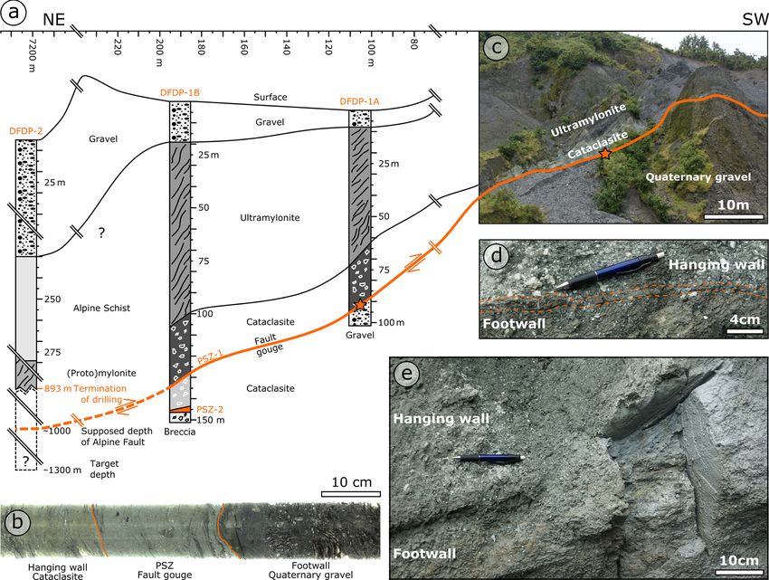
98                                           B. Schuck et al.: Fault zone architecture of a large plate-bounding strike-slip fault

Figure 2. (a) Plate tectonic setting of New Zealand’s South Island with the Alpine Fault’s onshore segment being highlighted in orange.
Position of (b) is indicated by black box. (b) Simplified geological map of the study area. Alpine Fault trace shown in orange. Locations of
investigated outcrops: Martyr River, 43◦ 70 4700 S 168◦ 330 4000 E; Havelock Creek, 43◦ 320 1500 S 169◦ 520 1500 E; Waikukupa Thrust, 43◦ 260 2200 S
170◦ 40 800 E; Gaunt Creek, 43◦ 180 5800 S 170◦ 190 2000 E. Map is based on the geological map of New Zealand’s South Island (Edbrooke et al.,
2015) and the digital elevation model of Columbus et al. (2011). (c) Typical shallow-depth sequence of Alpine Fault rocks. The figure was
modified from Norris and Cooper (2007). Extents of alteration zone were derived from Sutherland et al. (2012) and extents of inner and outer
damage zone from Townend et al. (2017).

within a matrix of pulverized host rock, authigenic chlorite,               Quaternary features (e.g., Cooper and Norris, 1990; Berry-
muscovite and illite (Sibson et al., 1979; Norris and Cooper,               man et al., 2012; Schuck et al., 2018). It is an incohesive and
2007; Boulton et al., 2012). Intense chloritization imparted a              fine-grained gouge up to ∼ 50 cm in thickness (Norris and
typical pale green color to these 10–30 m wide cataclasites                 Cooper, 2007; Boulton et al., 2012). Authigenic phyllosili-
(Warr and Cox, 2001), which are cemented by authigenic                      cates cement the PSZ converting it into an impermeable hy-
phases, dominantly phyllosilicates and carbonates (Suther-                  draulic barrier preventing cross-fault fluid flow (Sutherland
land et al., 2012; Toy et al., 2015; Williams et al., 2016). The            et al., 2012; Menzies et al., 2016). There is no location pro-
fault’s PSZ cross-cuts all other structures, which indicates                viding a continuous section from hard rock hanging wall to
that it is the last active part of the fault system and accom-              hard rock footwall (Townend et al., 2009).
modates the coseismic displacements that manifest as offset

Solid Earth, 11, 95–124, 2020                                                                              www.solid-earth.net/11/95/2020/
B. Schuck et al.: Fault zone architecture of a large plate-bounding strike-slip fault                                         99

2.4   The Deep Fault Drilling Project                              3     Methods

Studying the physical character of tectonic deformation at         3.1    Sampling
depth within a continental fault late in its interseismic period
provided the motivation for the Deep Fault Drilling Project        Fault rocks at Martyr River and Havelock Creek were sam-
(DFDP, Fig. 3a, Townend et al., 2009). Phase 1 drilled two         pled using hammer and chisel. At Waikukupa Thrust and
∼ 100 m (DFDP-1A) and ∼ 150 m (DFDP-1B) deep pilot                 Gaunt Creek samples were recovered using a hand-held
holes in January 2011 (Sutherland et al., 2012; Toy et al.,        chainsaw equipped with a silicon carbide chain. After re-
2015). These DFDP-1 boreholes provide a continuous sec-            covery, all outcrop samples were immediately wrapped in
tion of fault rocks from hanging wall ultramylonites to foot-      aluminum and plastic foil to slow down drying. This proce-
wall gravels enabling lithological (Toy et al., 2015), miner-      dure allowed for continuous transects across the PSZ, which
alogical (Schleicher et al., 2015), geomechanical (Boulton         juxtapose hanging wall cataclasites and footwall gravels, to
et al., 2014; Carpenter et al., 2014) and geophysical analysis     be sampled from Martyr River and Waikukupa Thrust. How-
(Sutherland et al., 2012; Townend et al., 2013). In total, three   ever, the samples broke apart along the PSZ during shipping.
∼ 20 cm thick PSZs were encountered. In DFDP-1A the PSZ            An intact contact of PSZ on footwalls material was only pre-
is located between 90.67 and 90.87 m depth (Fig. 3a, b), and       served from Gaunt Creek.
in DFDP-1B two PSZs were encountered at 128.30–128.50                 In summary, hanging wall fault rocks are available from
and 143.96–144.16 m depth, respectively (Fig. 3a, Toy et al.,      Martyr River, Waikukupa Thrust and DFDP-1A. PSZ sam-
2015).                                                             ples originate from all five locations and footwall rocks were
    Another two boreholes were drilled in DFDP phase 2             taken at Martyr River, Waikukupa Thrust and Gaunt Creek.
(DFDP-2A: 212.6 m MD – measured depth; DFDP-2B:
893.1 m MD) about 7.5 km ENE of the location of DFDP-              3.2    Microstructural analysis
1 (Fig. 2b, Toy et al., 2017). Phase 2 yielded cuttings for
petrographic investigations (Toy et al., 2017) and provided        Samples from Martyr River, Waikukupa Thrust and Gaunt
various insights into fault zone architecture by wireline logs     Creek were cut dry with a low-speed saw perpendicular and
(e.g., Janku-Capova et al., 2018; Massiot et al., 2018) but was    parallel to the fault trace. From all locations, subsamples
not able to penetrate and sample the fault core due to scien-      were selected for microstructural analyses and subsequently
tific and technical difficulties (Toy et al., 2017). DFDP bore-    embedded in resin prior to the preparation of 29 dry-polished
holes from both phases provide the opportunities for long-         thin sections using otherwise standard techniques.
term monitoring of the Alpine Fault (e.g., Sutherland et al.,         Microstructural investigations were conducted using opti-
2015).                                                             cal microscopy, scanning electron microscopy (SEM), trans-
                                                                   mission electron microscopy (TEM) and cathodolumines-
2.5   Study locations                                              cence analyses (CL). Thin sections were studied with a
                                                                   Leica DM RX optical microscope and a FEI Quanta 3D
For this study, all known outcrops with accessible PSZ be-
                                                                   SEM with focused ion beam (FIB; dual-beam machine).
tween Martyr River in the SW and Kokatahi River, SSE of
                                                                   The SEM, equipped with a field emission gun, operated at
Hokitika in the NE were investigated in the austral sum-
                                                                   20 kV in backscatter electron mode (BSE) and allowed semi-
mer 2015/2016 (Fig. 2b). Furthermore, cataclasite and the
                                                                   quantitative geochemical analyses with its EDAX energy dis-
fault gouge samples were available from the DFDP-1A core.
                                                                   persive X-ray analyzer (EDX). For TEM analyses, a plat-
Four of the five investigated locations, Havelock Creek,
                                                                   inum strip was deposited on the sites selected with the FIB
Waikukupa Thrust, Gaunt Creek and the core of DFDP-1A,
                                                                   of the SEM to enable subsequent preparation of 14 thin foils
are in the central segment of the Alpine Fault with the Alpine
                                                                   (10 × 8 × 0.15 µm) with a FEI FIB 200 following the pro-
Schist as hanging wall host rock. Rocks of the BST con-
                                                                   cedure outlined by Wirth (2004, 2009). A FEI Tecnai G2
stitute the host of fault rocks encountered at Martyr River,
                                                                   F20 X-Twin TEM with Gatan Tridiem energy filter, Fis-
the fifth and southwestern-most location. All outcrops are lo-
                                                                   chione high-angle annular dark field detector (HAADF) and
cated along river banks providing good outcrop conditions.
                                                                   EDX operated at 200 kV and allowed nanoscale investiga-
   Waikukupa Thrust is the only studied site that is consid-
                                                                   tion. Cathodoluminescence analyses on calcite veins and ce-
ered to be inactive. Incision of the Waikukupa River resulted
                                                                   ment were performed on thin sections using an Olympus po-
in a geomechanically unfavorable geometry leading to the
                                                                   larizing microscope. The Lumic HC1-LM hot cathode CL
abandonment of this thrust segment and re-localization of
                                                                   microscope operated at 14 kV, 0.0001 mbar and ∼ 0.6 mA
deformation approximately 700 m to the NE at Hare Mare
                                                                   electron beam and 2.5 A filament current, respectively.
Creek (Norris and Cooper, 1997).
                                                                      Microstructural analyses are mostly based on qualitative
                                                                   observations, but some quantitative information was ob-
                                                                   tained by image analysis using the open source software
                                                                   FIJI/ImageJ (Schindelin et al., 2012; Schneider et al., 2012).

www.solid-earth.net/11/95/2020/                                                                  Solid Earth, 11, 95–124, 2020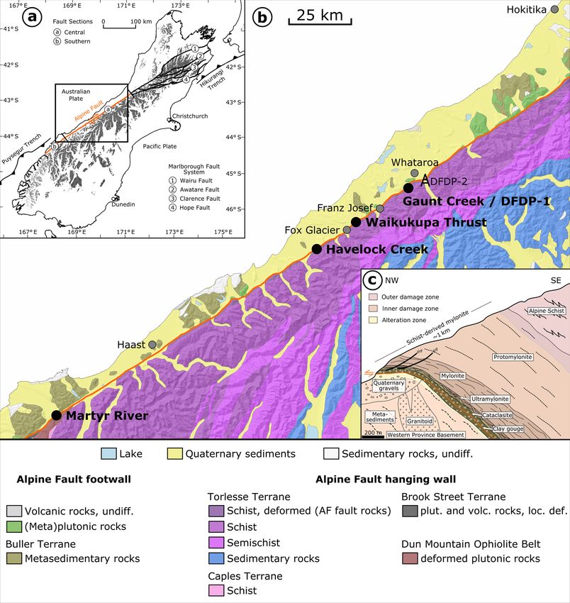
100                                        B. Schuck et al.: Fault zone architecture of a large plate-bounding strike-slip fault

Figure 3. (a) Schematic overview of Deep Fault Drilling Project (DFDP) boreholes drilled in phase 1 at Gaunt Creek and phase 2 within
the Whataroa River valley. Star at DFDP-1A indicates location of (b). (b) Segment of 180◦ scan of PSZ encountered at DFDP-1A drill
core (run 66, section 1). (c) Individual fault rock units of the Alpine Fault Zone are well-recognizable at the outcrop Gaunt Creek, in close
proximity to the DFDP boreholes. Star indicates location of (d) and (e). (d) An approximately 1 cm thick, brown layer indicated by stippled
orange lines, was interpreted to represent the PSZ at Gaunt Creek. (e) Sample location (specimen shown in Fig. 5b) some 10 s of centimeter
SW of location shown in (d). Figure modified according to Sutherland et al. (2012) and Boulton et al. (2014).

3.3     Mineralogical and geochemical investigations                     for quantitative mineralogy was performed using the pro-
                                                                         gram BGMN and the graphical user interface Profex (version
18 bulk rock powder samples for mineralogical and geo-                   3.10.2, Döbelin and Kleeberg, 2015) calibrated for the used
chemical analyses were prepared with a jaw crusher and sub-              diffractometer. The error of quantitative analyses is expected
sequently sieved to grain sizes < 62 µm. A McCrone mi-                   to be in the range of 3 wt %. Goodness of fit was assessed
cronization mill provided the < 10 µm grain size fraction for            by visually inspecting the differences between measured and
the quantitative mineralogical analysis.                                 modeled diffractograms and by aiming to obtain Rwp values
                                                                         lower than 3, a value arbitrarily chosen (Toby, 2006).
3.3.1    X-ray diffraction analysis                                         Bulk powder subsamples (45 mg), dispersed in 1.5 mL of
                                                                         de-ionized water and disaggregated in an ultrasonic bath,
The mineralogical compositions of the samples were deter-                were placed on round (∅ 3.1 cm) glass slides and air-dried
mined by X-ray diffraction (XRD) analysis on random pow-                 for subsequent smectite and chlorite analyses. Identification
der samples loaded from the back side of the sample holders              of smectite was performed after ethylene glycolation at 45 ◦ C
(∅ 16 mm). XRD analyses were performed with a PANalyt-                   for at least 12 h (2.4–25◦ 22), and heating to 500 ◦ C for 1 h
ical Empyrean X-ray diffractometer operating with Bragg–                 allowed us to differentiate between chlorite and kaolinite
Brentano geometry at 40 mA and 40 kV with CuKα radiation                 (2.4–25◦ 22, Moore and Reynolds Jr., 1997).
and a PIXel3D detector at a step size of 0.013◦ 22 from 4.6                 Illite polytype analyses to differentiate between authigenic
to 85◦ 22 and 60 s per step.                                             and detrital (i.e., comminuted muscovite) species were con-
   Mineralogy was determined qualitatively with the EVA                  ducted on selected samples with high illite and/or muscovite
software (version 11.0.0.3) by Bruker. Rietveld refinement

Solid Earth, 11, 95–124, 2020                                                                         www.solid-earth.net/11/95/2020/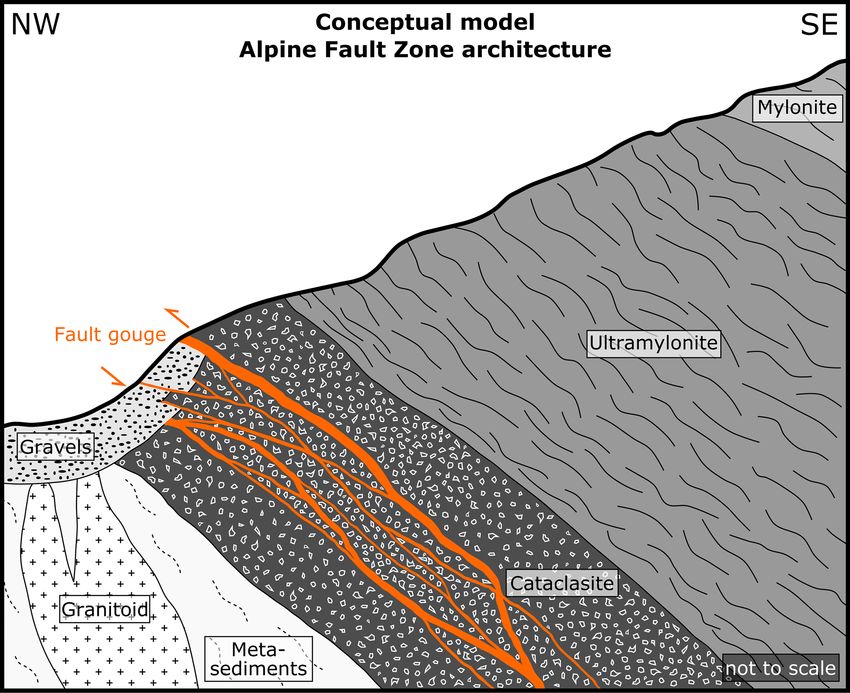
B. Schuck et al.: Fault zone architecture of a large plate-bounding strike-slip fault                                              101

concentrations (Moore and Reynolds Jr., 1997; Haines and               points, and these selections may be biased, we used a linear
van der Pluijm, 2008). Diffractograms for polytype analy-              best fit through all data points to determine isocon slopes.
ses were acquired between 16 and 44◦ 22 at a step size of                 Identification of the host rock is just as important as cor-
0.013◦ 22 with 200 s per step. All diffractograms and Rwp              rectly determining the slopes of the isocons (Grant, 1986).
values are provided in the Supplement.                                 We defined a reference protolith composition for fault rocks
                                                                       from Havelock Creek, Waikukupa Thrust, Gaunt Creek and
3.3.2   X-ray fluorescence spectrometry                                DFDP-1A (Table S1 in the Supplement) based on the average
                                                                       of geochemical compositions of Alpine Schist data reported
X-ray fluorescence spectrometry (XRF) with a PANalytical               by Grapes et al. (1982), Roser and Cooper (1990) and Toy
AXIOS Advanced spectrometer enabled study of geochemi-                 et al. (2017). These analyses are derived from the entire cen-
cal variations of major elements. For this purpose, after dry-         tral segment of the Alpine Fault and individual data points
ing of ∼ 1.1 g of bulk rock powder overnight at 105 ◦ C, 1 g           display little variation.
of sample material, 6 g of LiBO2 and 0.5–0.7 g of ammonium                At Martyr River, the geochemical compositions by Span-
nitrate, acting as oxidizing agent, were fusion digested at in-        dler et al. (2005, see their Table 1) have been averaged, and
creasing temperatures from 400 to 1150 ◦ C with a dilution             used as host rock composition (Table S1 in the Supplement).
of 1 : 6. The loss on ignition (LOI) providing volatile con-           Their analyses from Bluff Complex and Takitimu Mountains
tents was determined on 20–30 mg of powder samples with                were excluded, because the origin and some geochemical
an Euro EA Elemental Analyzer.                                         features, respectively, are different from the bulk BST (Span-
   To evaluate fluid-related element mobilization, XRF data            dler et al., 2005). We also note the isocon method has limi-
were analyzed based on the equation of Gresens (1967)                  tations for understanding fluid-assisted alteration related to
for composition–volume relationships resulting from meta-              fault activity at Martyr River. This is because the width of
somatic alterations, employing the isocon method (Grant,               the Alpine Fault deformation zone at this location is larger
1986, 2005). In this, the chemical composition of each inves-          than the thickness of the BST (Fig. 2b), so faulting-related
tigated fault rock sample (i.e., altered rock) is plotted against      fluid–rock interaction likely occurred with the DMOB and
the chemical composition of the host rock (i.e., unaltered             the geochemical composition of the reference protolith was
rock). An isocon, a straight line through the origin, separates        already affected by fluid-related alteration. Furthermore, the
species enriched relative to the host rock plotting above from         BST is compositionally very heterogeneous due to magmatic
those depleted plotting below. It follows the equation                 differentiation so it is difficult to choose a single representa-
CA = m × CH,                                                    (1)    tive host rock geochemical composition. Fortunately, these
                                                                       variations only substantially affect the absolute quantifica-
with C A and C H being element concentrations of the altered           tion. The method nevertheless allows for relative geochem-
and the host rock, respectively, and m referring to the iso-           ical changes within the fault zone at this location to be ac-
con’s slope. Enrichment or depletion (1Ci ) of an element i            counted for. The limitations regarding absolute quantification
relative to its host rock equivalent is calculated as follows:         of concentration changes as result of hydrothermal alteration
                                                                       also apply to the Alpine Schist.
1Ci     −1   CiA
    = m    ×     − 1.                                           (2)
CiH          CiH

   The inverse of the isocon’s slope (m−1 ) indicates overall          4     Results
mass gain (m−1 > 1) or loss (m−1 < 1), respectively. Mass
gains (%) are calculated as (m−1 − 1) × 100 %. A negative              4.1    Field observations
mass gain corresponds to a mass loss (%).
   To derive isocon slopes, Grant (2005) suggested five ap-            Individual units of the Alpine Fault rock sequence – (ul-
proaches: (I) clustering of CiA /CiH , (II) a best fit of data form-   tra)mylonites, cataclasites and footwall gravels – can be iden-
ing a linear array through the origin on an isocon diagram as          tified clearly at all sites investigated. However, weathering
graphical equivalent to (I), (III) assuming that certain ele-          and landslides complicate the unambiguous identification of
ments are immobile, or assuming (IV) mass or (V) volume                the PSZ at Gaunt Creek and Havelock Creek. This is exem-
to be constant during alteration. However, it has previously           plified by an approximately 1 cm thick, fine-grained, brown,
been shown that Al and Ti – elements commonly assumed to               fractured and discontinuous layer interpreted to represent the
be not affected by fluid-related alteration (e.g., Grant, 2005;        PSZ at Gaunt Creek (Fig. 3c–e) that was identified through
Dolejš and Manning, 2010) – are mobilized by fluid-related             sampling to be a footwall feature approximately 8 cm be-
alteration at the Alpine Fault. Furthermore, authigenic min-           low the PSZ (see Sect. 4.2.3). Furthermore, measurements
eral formation is thought to affect both fault rock mass and           of fault orientation are only robust in the well-exposed out-
rock volume (Schuck et al., 2018). As identification of clus-          crops at Waikukupa Thrust (50◦ /44◦ SE) and Martyr River
ters (I) or linear arrays (II) selects only a subset of all data       (59◦ /51◦ SE) and those from Gaunt Creek (61◦ /32◦ SE) and

www.solid-earth.net/11/95/2020/                                                                       Solid Earth, 11, 95–124, 2020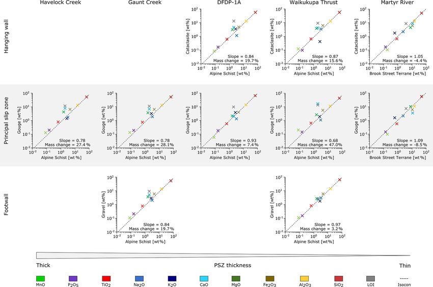
B. Schuck et al.: Fault zone architecture of a large plate-bounding strike-slip fault
www.solid-earth.net/11/95/2020/
Table 1. Summary of observed hanging wall cataclasite microstructures. PSZ: principal slip zone.
Poor Localization High
DFDP-1A Waikukupa Thrust Martyr River
Fractures X X X
– amount increases towards PSZ X X /
Microfaults ∼ 5 to ∼ 130 µm wide ∼ 5 to ∼ 130 µm wide /
Detrital clasts
– main phases quartz and feldspar quartz and feldspar polymineralic aggregates (mainly quartz,
feldspar and chlorite)
– minor phases / micas (elongated, kinked and fractured), hornblende quartz and feldspar (< 5 %)
and chlorite aggregates (up to 0.6 × 1 mm large)
– roundness angular–rounded angular–rounded angular–rounded
– sphericity low–moderate low–moderate low–moderate
– amount
– PSZ proximal ∼ 50 % (at ∼ 3 m above PSZ) ∼ 60 % to ∼ 70 % (at ∼ 70 cm above PSZ) not sampled
– at contact to PSZ ∼ 10 % ∼ 20 % to ∼ 25 % ∼ 40 % to ∼ 50 %
– size
– PSZ proximal ∼ 100 s of µm (at ∼ 3 m above PSZ) ∼ 100 s of µm (at ∼ 70 cm above PSZ) not sampled
– at contact to PSZ ∼ 100 µm ∼ 100 µm ∼ 100–200 µm
– maximum ∼ 550 × 600 µm ∼ 550 × 600 µm ∼ 200 µm
Fragments
– schist 1.6 × 3.4 mm large 2.8 × 5.4 mm large 1.1 mm large
– fractured and gouge filled X X /
– mylonite / 9–12 mm large /
– fractured and gouge filled / X /
Matrix clasts X X /
– first observation ∼ 1.35 m above PSZ ∼ 10 cm above PSZ /
– max. size 650 × 750 µm 1.3 × 3.4 mm
Patches of authigenic chlorite X X /
crystallites
– amount increases towards PSZ X X /
Bright matrix X X X
clasts
Calcite
– occurrence all samples mostly in direct vicinity to PSZ all samples
Solid Earth, 11, 95–124, 2020
– kind: cement within some fractures; local within some fractures; generally insignificant; within some fractures; finely dispersed and abundant
slightly more pronounced within ∼ 3 cm of PSZ
– kind: lenses up to 1.2 × 4 mm / /
– kind: veins frequent with increasing abundance towards the PSZ; ∼< 15 µm thick; mutually cross-cutting with small (< /
mostly restricted to clasts; up to 5–300 µm thick; typi- 20 µm), dextral offsets
cally between 50 and 70 µm thick
Foliation locally and weak; formed by clasts and microfaults; clast lenses parallel to PSZ /
locally with SC geometry
Other / breccias (< 100 µm large) within some centimeters /
above the PSZ; clay–clast aggregates
102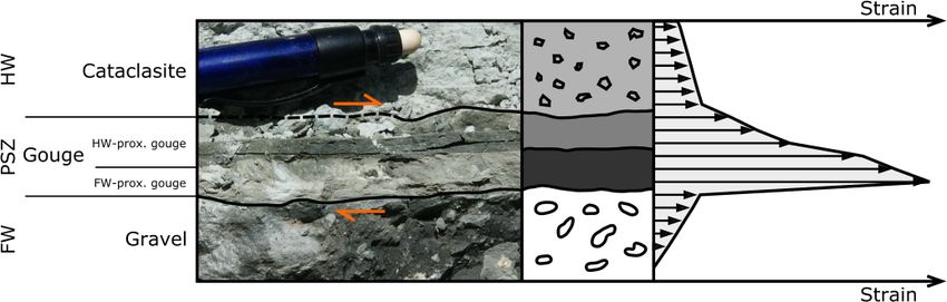
B. Schuck et al.: Fault zone architecture of a large plate-bounding strike-slip fault 103
Havelock Creek (102◦ /55◦ SE) should be treated with cau- close to the contact with the PSZ (< 1.35 m at DFDP-1A
tion. and < 10 cm at Waikukupa Thrust, respectively). In contrast,
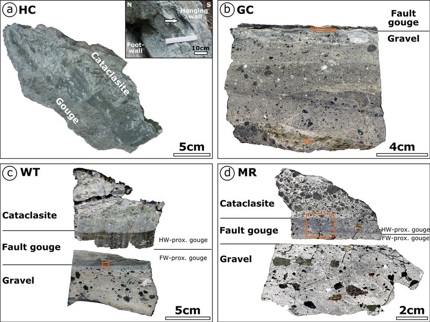
Thicknesses of fault gouges constituting the PSZ vary quartz and feldspars only constitute ∼ 5 % of clasts at Mar-
among individual locations, including the DFDP-1A core tyr River. There, most clasts are polymineralic aggregates
(Figs. 3–5), and decrease in the following order: Havelock consisting of quartz, feldspar, chlorite and rarely biotite and
Creek (∼ 50 cm; Figs. 4a and 5a), Gaunt Creek (∼ 30–40 cm; fragments of calcite veins (Fig. 6f and g). There are subor-
Figs. 3c–e and 5b), DFDP-1A (20 cm; Fig. 3b), Waikukupa dinately fragments of Alpine Schist (all locations) and my-
Thrust (∼ 4 cm; Figs. 4b and 5c) and Martyr River (∼ 1– lonites (Waikukupa Thrust). At DFDP-1A and Waikukupa
2 cm; Figs. 4c, d and 5d). Except for Martyr River, these lo- Thrust these fragments display ∼ 150 µm wide, gouge-filled
cations have the same protolith (Fig. 2b; see Sect. 4.3). Fur- microfaults (Table 1). At Waikukupa Thrust, there are also
thermore, there is no systematic variation of PSZ thickness clay–clast aggregates (CCAs; Boutareaud et al., 2008). At
in distance along strike in these outcrops. both thin section and outcrop scale, the amount and size of
clasts generally decrease towards the PSZ and both vary sys-
4.2 Microstructures tematically with PSZ thickness (Table 1; see also Boulton
et al., 2012; Toy et al., 2015): locations with a thinner PSZ
The fault rocks of Alpine Fault hanging wall, PSZ and foot- contain more clasts in the hanging wall, which tend to be
wall contain clasts embedded in a fine-grained matrix. We larger, compared to locations with a thicker PSZ.
define matrix as fine particles – detrital and authigenic – Open cracks, typically several millimeters long and up
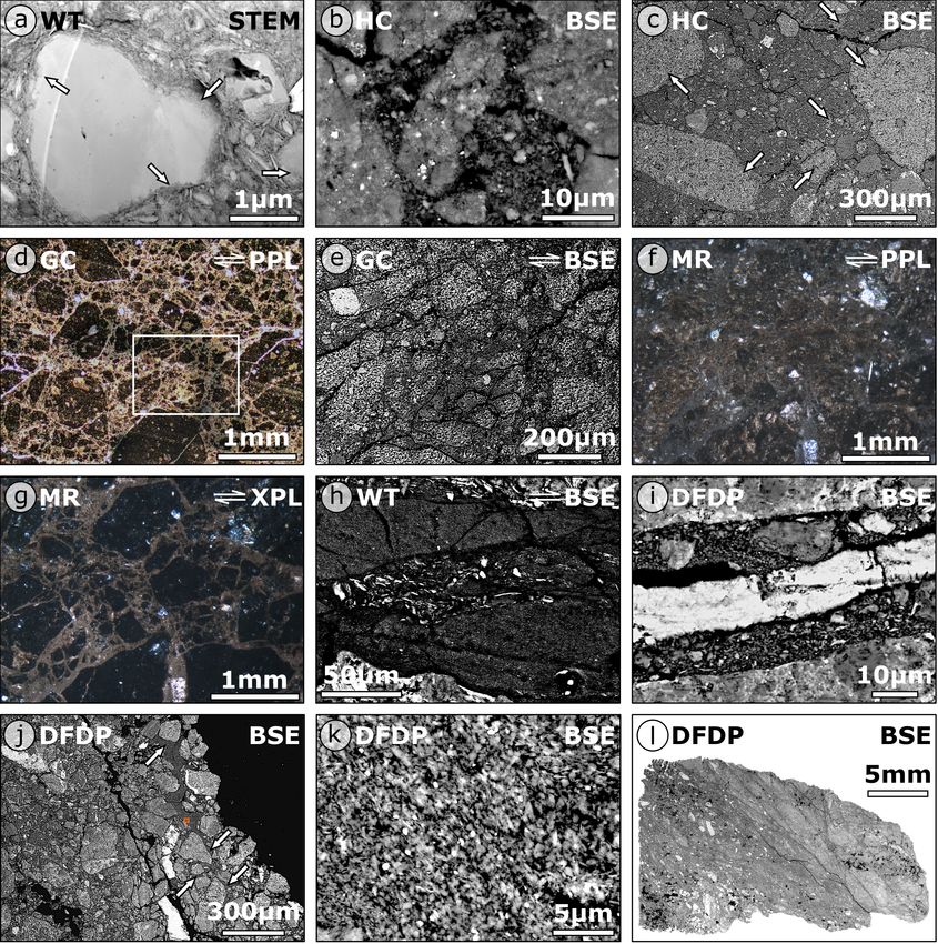
belonging to the clay-size fraction, i.e., < 2 µm (Fig. 6a). to hundreds of micrometer wide, increase in abundance to-
In fact, the typical matrix grain size is
1 µm. The ma- wards the PSZ at DFDP-1A and Waikukupa Thrust. Further-
trix is composed of abundant phyllosilicates of detrital (see more, microfaults (∼ 5–130 µm thick) cross-cut cataclasites
Sect. 4.3) and authigenic (e.g., Fig. 6a) origin and detrital at these locations. They contain comminuted particles and
particles, mostly quartz and feldspar. The latter are subangu- authigenic phyllosilicates and range in maturity: mature mi-
lar to rounded in shape with elongate to moderate sphericity crofaults display a well-developed fine-grained fault gouge
and commonly with edges that have been affected by disso- with particles up to tens of micrometers in size but mostly
lution and mineral alteration processes (Fig. 6a). smaller than 2 µm (Fig. 6h). In contrast, juvenile microfaults
Clasts embedded in the fault rock matrix are predomi- contain poorly sorted particles up to a few hundred microm-
nantly comminuted quartz, feldspar and mica grains, as well eters in size with the majority larger than 10 µm. In addition,
as fragments of Alpine Schist and mylonite. In addition, there some microfaults have cores made of coarser-grained matrix
are two more groups of clasts. The first one comprises com- and clasts (Fig. 6h) or calcite veins (Fig. 6i) surrounded by
pact, almost pore-free, fine particles with distinct boundaries fine-grained gouge.
but of similar composition compared to the surrounding ma- Locally, there are patches almost completely devoid of
trix (Fig. 6b). This group of clasts is termed matrix clasts clastic particles but with abundant authigenic flake- to
in the following. The second group comprises small areas, needle-shaped chlorite crystals cementing pores and frac-
which are microstructurally similar to matrix clasts. These tures at Waikukupa Thrust and DFDP-1A (Fig. 6j and k).
features are characterized by brighter grey values in BSE The amount of these chlorite-dominated areas and authi-
mode, and typically high porosities so they are easy to differ- genic phyllosilicates in general increases with decreasing
entiate from the surrounding material (Fig. 6c). EDX analy- distance to the PSZ and progressively cements the fault
ses demonstrate that they are compositionally identical to the rocks. Furthermore, the matrix is cemented by calcite (Ta-
surrounding matrix. Because comparison of optical and scan- ble 1). Whereas finely dispersed calcite is abundant at Mar-
ning electron microscopy images reveals that these structures tyr River, calcite at Waikukupa Thrust is usually present only
look like matrix clasts under plain polarized light (Fig. 6d in direct vicinity (< 3 cm) to the PSZ. There, mutually cross-
and e), we refer to them as bright matrix clasts in the follow- cutting calcite veins (∼ 15 µm thick) display small (< 20 µm)
ing. dextral offsets (see Fig. 3f in Schuck et al., 2018). Further-
The distinct lithological and (micro-to-macro) structural more, there are < 100 µm large calcite-cemented breccias
characteristics of all units are described in detail in the fol- composed of angular fragments of clastic particles and ma-
lowing sections and summarized in Tables 1 (hanging wall), trix clasts (see Fig. 3c in Schuck et al., 2018). At DFDP-1A,
2 (PSZ) and 3 (footwall). calcite is encountered in lenses and veins, which frequently
cross-cut clasts but rarely the matrix and generally increase
4.2.1 Hanging wall cataclasites in abundance towards the PSZ.
Locally, cataclasites are foliated. At DFDP-1A, clasts to-
Clasts embedded in the fine-grained cataclasite matrix at gether with microfaults define a weak foliation (Fig. 6l) vary-
DFDP-1A and Waikukupa Thrust are mostly quartz and ing non-systematically across the investigated interval, lo-
feldspars, with commonly fractured, dissolved and altered cally displaying SC geometry. At Waikukupa Thrust and
edges (Fig. 6a). Furthermore, matrix clasts are encountered
www.solid-earth.net/11/95/2020/ Solid Earth, 11, 95–124, 2020104 B. Schuck et al.: Fault zone architecture of a large plate-bounding strike-slip fault
Figure 4. Outcrops of Alpine Fault Zone rocks. (a) Whereas pale green hanging wall cataclasites and larger Quaternary footwall gravels
are clearly identified at Havelock Creek, the contacts and hence thickness of the PSZ (indicated by arrows) to overlying and underlying
units, respectively, are only poorly constrained. The white box indicates position of Fig. 5a. (b) The PSZ at Waikukupa Thrust as indicated
by arrows is well-defined and straight. The black box gives location of sample presented in Fig. 5c. (c) At Martyr River, hanging wall and
footwall rocks are sharply separated by a well-defined PSZ (indicated by arrows). The white box indicates position of (d). The star gives the
sample location for the specimen shown in Fig. 5d. (d) The PSZ at Martyr River is between 1 and 2 cm thick. HC: Havelock Creek; WT:
Waikukupa Thrust; MR: Martyr River.
close to the PSZ, cataclastic lenses exhibit a very weak fo- dominate (Fig. 7b). Bright matrix clasts are present at all lo-
liation parallel to the shear plane. cations, but are abundant only at Havelock Creek and Gaunt
Creek, where they, in addition to clast-like shapes, occupy ar-
4.2.2 Principal slip zone fault gouges eas of several hundred micrometers. In general, the amount
and size of clasts weakly correlate with PSZ thickness (Ta-
The type of contact between hanging wall cataclasites and ble 2). Where the PSZ is thinner, clasts tend to be more abun-
the fault gouge appears to correlate with PSZ thickness: dant and sizes tend to be larger. Clast sizes increase in the
where the PSZ is thicker, contacts are transitionally man- following order: Gaunt Creek (∼ 75 µm), Havelock Creek
ifested by decreasing grain sizes (Table 2), as exemplified (∼ 75 µm), Waikukupa Thrust (∼ 100 µm) and Martyr River
at Havelock Creek with its transitional, poorly developed (tens of micrometers to ∼ 200 µm).
contact over 8 cm (Fig. 5a). In contrast, Waikukupa Thrust It is not possible to determine the amount and size of
has a sharp contact on the outcrop and hand specimen scale clasts within the DFDP-1A core, because more than 90 %
(Figs. 4b and 5c), but displays a transition over 4 mm from of this unit is cemented by authigenic phyllosilicates, mostly
a porous, clast-rich cataclasite matrix to a very dense PSZ chlorite (Fig. 7e and f). Authigenic phyllosilicates tend
matrix as revealed by microscopic inspection (see Fig. 3a in to nucleate along crack and grain boundaries of fractured
Schuck et al., 2018). Identification of the sharp but undulat- grains. Additionally, newly formed phyllosilicates replace
ing contact at Martyr River is simple on the outcrop and hand dissolved larger particles and mimic their original shape.
specimen scale (Figs. 4c, d and 5d), but difficult on the mi- Non-cemented areas are restricted to fractures. Many of these
croscale (Fig. 7a and b). fractures contain up to 350 µm wide calcite cores, locally sur-
Matrix clasts are the prevailing type of clast at Waikukupa rounded by gouge, microstructurally similar to microfaults
Thrust and Havelock Creek (Fig. 7c and d), but constitute observed within the DFDP-1A cataclasites (see Fig. 6i).
less than 5 % of clasts at Martyr River. Furthermore, the These non-cemented, fracture-related locations host patches
phyllosilicate-cemented fault gouge at Martyr River hosts in- of fine-grained, randomly oriented and needle-shaped, au-
dividual mineral phases, which is distinctly different from its thigenic chlorite crystallites. The presence of these patches
hanging wall, where large, fine-grained chloritized particles within the PSZ is restricted to DFDP-1A.
Solid Earth, 11, 95–124, 2020 www.solid-earth.net/11/95/2020/Table 2. Summary of observed principal slip zone (fault gouge) microstructures. PSZ: principal slip zone; HW: hanging wall; FW: footwall.
Poor Localization High
Havelock Creek Gaunt Creek DFDP-1A Waikukupa Thrust Martyr River
Contact HW–PSZ transitional over 8 cm not sampled not sampled sharp at macroscale and mesoscale;
transitional over 4 mm at microscale
and sharp at macroscale and mesoscale;
difficult to identify at microscale
Major differences compared to hanging wall not sampled not sampled ∼ 90 % of PSZ is cemented FW-prox. gouge: dense anastomosing (I) clasts are small individual mineral
network of mutually cross-cutting phases and not chloritized aggregates;
www.solid-earth.net/11/95/2020/
calcite veins (II) no calcite cement, but less porous
due to authigenic phyllosilicates
Kind of PSZ single structure single structure single structure layered; HW-prox. gouge 2 cm thick; layered; HW-prox. gouge 0.8–1 cm
FW-prox. gouge 2 cm thick thick; FW-prox. gouge 0.3–0.5 cm thick
– contact between PSZ layers / / / sharp and undulating and poorly
developed at microscale
– major differences between PSZ layers / / / FW-prox. gouge hosts dense, 20 %–25 % clasts in HW-prox. gouge
anastomosing network of mutually vs. 25 %–30 % clasts in
cross-cutting calcite veins FW-prox. gouge
Similarities between investigated PSZs HW-prox. gouge at Waikukupa FW-prox. gouge at Waikukupa / Havelock Creek (HW-prox. gouge); /
Thrust Thrust Gaunt Creek (FW-prox. gouge)
Detrital clasts
– main phases quartz and feldspar quartz and feldspar quartz and feldspar quartz and feldspar quartz and feldspar
– minor phases hornblende and mica fragments / / / hornblende; mica fragments (< 20 µm
(50 × 350 µm large) large) and needle-shaped serpentines
(< 20 µm large)
– roundness (sub)angular–rounded (sub)angular–rounded (sub)angular–rounded (sub)angular–rounded (sub)angular–rounded
– sphericity elongate–moderate elongate–moderate elongate–moderate elongate–moderate elongate–moderate
– amount 10 % < 1% / HW-prox. gouge: 5 %–10 %; FW-prox. 20 %–30 %
gouge: < 1 %
– size ∼ 75 µm ∼ 15 µm / ∼ 100 µm; decreases towards FW HW-prox. gouge tens µm to
∼ 200 µm; FW-prox. gouge < 100 µm
– maximum 160 × 250 µm 90 × 130 µm / 110 × 180 µm 1 mm
– fragments
B. Schuck et al.: Fault zone architecture of a large plate-bounding strike-slip fault
– kind schist / / / schist, mylonite, cataclasite
– roundness subangular–rounded / / / subangular–rounded
– sphericity low–moderate / / / low–moderate
– size 15–50 µm / / / 100 s of micrometer (schist)
– maximum 400 × 450 µm / / / > 2.2 × 3.7 mm (schist); 3 × 7.5 mm
(mylonite); 5 × 6 mm (cataclasite)
– other / / / clast size decreases towards FW /
Matrix clasts prevailing type of clast / / prevail at HW-prox. gouge < 5 % of clasts
– maximum size 650 × 830 µm / / 3 µm to > 6 mm ∼ 20 µm to 3 × 3.5 mm
Patches of authigenic chlorite crystallites / / associated with non-cemented / /
fractures
Bright matrix clasts
– abundance high high low (local) / low (local)
Solid Earth, 11, 95–124, 2020
105B. Schuck et al.: Fault zone architecture of a large plate-bounding strike-slip fault
www.solid-earth.net/11/95/2020/
Table 2. Continued.
Poor Localization High
Havelock Creek Gaunt Creek DFDP-1A Waikukupa Thrust Martyr River
Calcite veins very rare network rare rare (HW-prox. gouge); network (FW- rare
prox. gouge)
– thickness
– vein network / 350–800 µm / ∼ 2 cm (FW-prox. gouge) /
– individual veins / 5–10 µm, up to 30 µm, increases up to 350 µm HW-prox. gouge ∼ 10 µm; 15–900 µm
slightly towards FW FW-prox. gouge typically ∼ 60 µm, be-
tween 1.5 and 200 µm decreases to FW
– spacing / 20–30 µm; between 10 and 80 µm / 200 µm (close to HW-prox. gouge), /
10 µm (close o FW)
– orientations / / / FW-prox. gouge; (I) /
subparallel to displacement; II) oblique
to displacement; (III) normal to dis-
placement
– CL color / mostly uniform yellow–orange; / uniform yellow–orange /
slightly brighter and more
yellow to FW
– other / / / small (< 5 µm), blocky and euhedral /
crystals
Foliation / / / / in HW-prox. gouge, weak, parallel to
PSZ, formed by clasts
Other / / slickolite HW-prox. gouge: clay–clast aggregates /
and breccias (0.6 × 1.2 mm)
Solid Earth, 11, 95–124, 2020
106B. Schuck et al.: Fault zone architecture of a large plate-bounding strike-slip fault 107 Figure 5. Investigated outcrop samples. (a) The contact between hanging wall cataclasites and thick fault gouge at Havelock Creek is poorly developed and appears to be transitional over ∼ 8 cm. The inset provides a close-up of the sample location (indicated by the arrow). (b) Identifying the fault gouge in the field at the location Gaunt Creek turned out to be difficult. Consequently, only the lowermost part of the PSZ has been sampled. Contact between the PSZ and footwall is sharp. The orange box at the contact indicates location of Fig. 7k–m; the orange box at the bottom indicates location of Fig. 6d. (c) The thin fault gouge at Waikukupa Thrust consists of a hanging wall-proximal and footwall-proximal layer. The orange box gives location of Fig. 7j. (d) The contacts of the thin PSZ with hanging wall and footwall rocks, respectively, are sharp at Martyr River. Fault gouge consists of a hanging wall-proximal and a footwall-proximal layer. The orange box gives location of Fig. 7a and b. HC: Havelock Creek; GC: Gaunt Creek; WT: Waikukupa Thrust; MR: Martyr River. We only saw evidence of pressure solution at one location, layer at Waikukupa Thrust (Fig. 7h and i). Furthermore, both DFDP-1A, where there is a slickolite (Fig. 7g), a stylolite gouges exhibit calcite vein networks close to the contact with with teeth oblique to the stylolite surface (see Passchier and the footwall (Fig. 7j–m). At Waikukupa Thrust, veins dis- Trouw, 2005). However, enrichment of insoluble material or play mutual cross-cutting relationships with dextral offsets. secondary phases along teeth-crowns is not observed. For a detailed description of these calcite veins, the reader PSZs at Waikukupa Thrust and Martyr River are layered is referred to the preceding work of Schuck et al. (2018). At and display a hanging wall-proximal and a footwall-proximal Gaunt Creek, the 350–800 µm wide vein network (Fig. 7k– layer, respectively (Fig. 5c and d). At Martyr River, the con- m) has been subsequently affected by intensive fracturing tact is best recognized on the hand specimen scale (Figs. 4d, and calcite dissolution, which hampers the identification of 5d, 7a and b), where the fault gouge is blueish-grey proximal cross-cutting relationships. Furthermore, the contact between to the hanging wall and greenish-grey proximal to the foot- calcite veins and the surrounding gouge is poorly developed. wall. Minor differences between both gouge layers are mani- Veins are typically 5–10 µm wide and tend to be thicker, less fested by slightly more and larger clasts in the ∼ 0.8–1 cm dissolved and deformed close to the footwall. CL colors are thick hanging wall-proximal layer than the ∼ 0.3–0.5 cm yellow–orange but slightly brighter and more yellow towards thick footwall-proximal layer (20 %–25 % vs. 25 %–30 %; the footwall (Fig. 7l). Table 2). Apart from these vein networks, calcite veins cross- At Waikukupa Thrust, a sharp but undulating contact cut matrix clasts at Martyr River and the hanging wall- separates a brown-dark grey hanging wall-proximal layer proximal gouge layer of Waikukupa Thrust, but are very with 5 %–10 % clasts from a medium-light grey footwall- rare at Havelock Creek. Additional hanging wall-proximal proximal layer, which is clast-poor (< 1 % clasts; usually microstructures are clasts forming a weak foliation parallel < 5 µm large). to displacement at Martyr River and CCAs at Waikukupa The dense, clast-poor (< 1 % clasts) fault gouge at Gaunt Thrust. Furthermore, hanging wall-proximal microstructures Creek is microstructurally identical to the footwall-proximal at Waikukupa Thrust are similar to those of Havelock Creek www.solid-earth.net/11/95/2020/ Solid Earth, 11, 95–124, 2020
108                                         B. Schuck et al.: Fault zone architecture of a large plate-bounding strike-slip fault

Figure 6. (a) Particles forming the fault rock matrix are defined as smaller than 2 µm. Abundant authigenic phyllosilicates cement the matrix.
Arrows indicate albite dissolution and alteration to phyllosilicates. (b) Matrix clasts, low-porosity, compact and clast-like areas of similar
composition as the matrix, are embedded within the fault rock matrix at all outcrops. (c) Bright matrix clasts (arrows) surrounded by fine-
grained matrix and some clasts. (d) Lens of matrix clasts within footwall gravels at Gaunt Creek (see Fig. 5b). The white box indicates
location of (e). (e) SEM analysis shows that clasts within a lens ∼ 8–8.5 cm below the PSZ at Gaunt Creek are bright matrix clasts. (f,
g) Corresponding PPL (f) and XPL (g) photomicrographs of hanging wall clasts at Martyr River. Identification of constituting mineral phases
– mostly quartz, feldspar, chlorite – is only possible by EDX analysis. (h) Mature microfault filled by fine-grained authigenic phyllosilicates
with typical grain sizes < 2 µm and a core of coarser-grained material. (i) Microfault displaying a calcite vein within its core surrounded by a
fine-grained matrix and some larger clasts. (j) Locally, pores and cracks are cemented by fine-grained, authigenic phyllosilicates (arrows). The
orange box indicates location of (k). (k) Matrix-cementing authigenic phyllosilicates are mostly flake- to needle-shaped chlorite crystallites.
(l) Foliated cataclasite (top left to bottom right) sampled 25 cm above the PSZ. WT: Waikukupa Thrust; HC: Havelock Creek; GC: Gaunt
Creek; MR: Martyr River; DFDP: Deep Fault Drilling Project core 1A; STEM: scanning transmission electron microscopy; BSE: backscatter
electron microscopy; PPL: plane polarized light; XPL: cross-polarized light.

(Fig. 7c and d), except that clasts are not homogeneously dis-            7j–m). Footwall gravels are compositionally similar to over-
tributed but cluster randomly at Havelock Creek. Apart from               lying hanging wall cataclasites and fault gouges (Table 3).
the hanging wall-proximal fault gouge layer of Waikukupa                  Furthermore, the same correlations regarding amount and
Thrust, where typical clast size decreases while the size of              size of clasts observed in hanging wall cataclasites and fault
matrix clasts increases towards the footwall, trends regarding            gouges are seen within footwall gravels (Table 3): locations
microstructures are not observed. Most remarkably, discrete               with thin PSZ tend to contain more and larger clasts than
slip planes are not observed within the fault gouges.                     locations with thicker PSZ. In addition, grain size increases
                                                                          with increasing distance from the PSZ. Whereas there are
4.2.3   Footwall gravels                                                  some bright matrix clasts at Martyr River and Gaunt Creek,
                                                                          matrix clasts are only encountered at Gaunt Creek. At Mar-
Where sufficiently exposed, the contact between clast-poor
PSZ and clast-bearing footwall is sharp (Figs. 4b–d; 5b, c;

Solid Earth, 11, 95–124, 2020                                                                           www.solid-earth.net/11/95/2020/
B. Schuck et al.: Fault zone architecture of a large plate-bounding strike-slip fault 109
Figure 7. (a) BSE and (b) XPL photomicrographs of the fault core at Martyr River. Identification of the contact between the hanging
wall and PSZ (stippled line) and that between the hanging wall- and footwall-proximal gouge (dotted line), respectively, is difficult. (c, d)
The hanging wall-proximal gouge at Waikukupa Thrust (c) with its large amount of matrix clasts is microstructurally similar to the PSZ
at Havelock Creek (d). (e) Photomicrograph of typical microstructures of cemented PSZ at DFDP-1A core. (f) Cemented PSZ matrix of
the DFDP-1A core. Pores between comminuted and dissolved (arrow) quartz grains are cemented by authigenic phyllosilicates, mostly
chlorite. (g) Slickolite (white arrows) indicative of pressure solution. (h, i) Fault gouge at Gaunt Creek (h) is microstructurally similar
to footwall-proximal gouge at Waikukupa Thrust (i). (j) Network of anastomosing calcite veins within footwall-proximal gouge layer at
Waikukupa Thrust. The contact between fault gouge and footwall (orange line) is sharp. (k, l, m) The basal part of the PSZ at Gaunt Creek
hosts a network of calcite veins terminating at the sharp contact (white/orange stippled line) with the footwall (FW). MR: Martyr River;
WT: Waikukupa Thrust; HC: Havelock Creek; DFDP: Deep Fault Drilling Project core 1A; GC: Gaunt Creek; BSE: backscatter electron
microscopy; XPL: cross-polarized light; STEM: scanning transmission electron microscopy; CL: cathodoluminescence.
tyr River, footwall clasts are slightly imbricated and form a within this lens is < 5 %. Fractures between the individ-
weak foliation parallel to displacement. ual clasts are filled with a fine-grained matrix. SEM analy-
Calcite is absent at Martyr River and restricted to a sis reveals that these clasts are actually bright matrix clasts
∼ 3 mm thick layer immediately adjacent to the PSZ at (Fig. 6e).
Waikukupa Thrust. There, calcite constitutes finely dispersed
cement, veinlets and < 5 µm thick rims at grain edges paral- 4.3 Mineralogy
lel to displacement. In contrast, at Gaunt Creek, calcite is pre-
dominantly found in veins and lenses cross-cutting the matrix
There are only minor variations in the qualitative fault rock
and detrital clasts.
composition (Table 4). Quartz, feldspar, calcite and phyl-
The ∼ 1 cm thick, fine-grained, brown layer erroneously
losilicates (chlorite, kaolinite, muscovite, illite and biotite)
interpreted as PSZ at Gaunt Creek (Fig. 3d and e), is mainly
and traces of apatite, pyrite and rutile are always present.
composed of fractured, subangular to subrounded matrix
Additionally, Waikukupa Thrust and Havelock Creek con-
clasts (Fig. 6d). The amount of quartzofeldspathic clasts
tain amphiboles, mainly hornblende, and there is epidote at
www.solid-earth.net/11/95/2020/ Solid Earth, 11, 95–124, 2020You can also read