Flat-Top Cylinder Indenter for Mechanical Characterization: A Report of Industrial Applications - MDPI
←
→
Page content transcription
If your browser does not render page correctly, please read the page content below
materials
Article
Flat-Top Cylinder Indenter for Mechanical Characterization:
A Report of Industrial Applications
Roberto Montanari *                  and Alessandra Varone

                                          Department of Industrial Engineering, University of Rome “Tor Vergata”, 00133 Rome, Italy;
                                          alessandra.varone@uniroma2.it
                                          * Correspondence: roberto.montanari@uniroma2.it; Tel.: +39-06-72597182

                                          Abstract: FIMEC (flat-top cylinder indenter for mechanical characterisation) is an instrumented
                                          indentation test employing a cylindrical punch. It has been used to determine the mechanical
                                          properties of metallic materials in several applications of industrial interest. This work briefly
                                          describes the technique and the theory of indentation with a flat-ended punch. The flat indentation
                                          of metals has been investigated through experimental tests, and an equation has been derived to
                                          calculate the yield stress from the experimental data in deep indentation. The approach is supported
                                          by many data on various metals and alloys. Some selected case studies are presented in the paper:
                                          (i) crank manufacturing through pin squeeze casting; (ii) the evaluation of the local mechanical
                                          properties in a carter of complex geometry; (iii) the qualification of Al billets for extrusion; (iv) stress–
                                          relaxation tests on CuCrZr heat sinks; (v) the characterization of thick W coatings on CuCrZr alloy;
                                          (vi) the measure of the local mechanical properties of the molten-zone (MZ) and the heat-affected
                                          zone (HAZ) in welded joints. The case studies demonstrate the great versatility of the FIMEC test
                                          which provides information not available by employing conventional experimental techniques such
                                as tensile, bending, and hardness tests. On the basis of theoretical knowledge and large amount

                                          of experimental data, FIMEC has become a mature technique for application on a large scale in
Citation: Montanari, R.; Varone, A.
                                          industrial practice.
Flat-Top Cylinder Indenter for
Mechanical Characterization: A
                                          Keywords: indentation test; FIMEC; material characterization; mechanical properties; industrial
Report of Industrial Applications.
                                          application
Materials 2021, 14, 1742. https://
doi.org/10.3390/ma14071742

Academic Editor: Daolun Chen
                                          1. Introduction
Received: 31 January 2021                       FIMEC (flat-top cylinder indenter for mechanical characterisation) is an instrumented
Accepted: 29 March 2021                   indentation test that was originally developed for measuring the mechanical properties of
Published: 1 April 2021                   irradiated materials, in particular the candidates for applications in future nuclear fusion
                                          reactors [1,2]. In this case materials selection is a challenging task because their neutron
Publisher’s Note: MDPI stays neutral      energy spectrum has a hard component peaked at 14 MeV, not present in the spectrum
with regard to jurisdictional claims in   of fission nuclear reactors. For long time the availability of such neutron source has been
published maps and institutional affil-
                                          recognized as a primary necessity in the community involved in the development of
iations.
                                          materials for fusion reactors; now, a D-Li neutron source (IFMIF) is under development. Its
                                          mission is to produce high energy neutrons at sufficient intensity and irradiation volume
                                          to test samples of candidate materials. The relatively small volume of the IFMIF irradiation
                                          chamber (about 500 cm3 for the higher fluence zone of about 20 dpa/year), the large
Copyright: © 2021 by the authors.         number of specimens required for the mechanical characterization of irradiated materials,
Licensee MDPI, Basel, Switzerland.        the strong gradient of the irradiation flux, as well as the high irradiation cost impose the use
This article is an open access article    of miniaturized probes. The mechanical properties (dynamic fracture toughness, tensile,
distributed under the terms and
                                          creep, stress-relaxation, fatigue etc.) should be determined by using miniaturized probes.
conditions of the Creative Commons
                                          Data obtained from such tests differ in general from those of standard mechanical tests. To
Attribution (CC BY) license (https://
                                          assess bulk properties, it is necessary to use empirical expressions that represent a serious
creativecommons.org/licenses/by/
                                          drawback.
4.0/).

Materials 2021, 14, 1742. https://doi.org/10.3390/ma14071742                                               https://www.mdpi.com/journal/materials
Materials 2021, 14, 1742                                                                                            2 of 19

                                 A cylindrical punch of sintered tungsten carbide (diameter = 1 mm and axial
                           length = 1.5 mm) is commonly employed in FIMEC test; punches of a smaller size (down
                           to 0.5 mm) are also used, depending on the material characteristics and the zone examined.
                           The method allows one to perform several tests on a small volume of material; thus, it is of
                           great interest for the characterization of irradiated materials [3,4].
                                 The test provides applied load vs. penetration depth curves and can be performed at
                           different temperatures from −196 ◦ C up to +600 ◦ C. The properties which can be deter-
                           mined from FIMEC test are yield stress [1], elastic modulus [5,6], ductile to brittle transition
                           temperature (DBTT) [2,4], surface creep [1] and stress relaxation [6,7]. The experimental
                           apparatus and data processing are quite simple; the test is non-destructive and the local
                           properties of mechanical parts of complex geometry can be easily determined, including
                           those of the molten zone (MZ) and the heat-affected zone (HAZ) in welded joints [8–10].
                           In comparison with other indentation tests operating on a micro- and nano-scale, a clear
                           advantage is that the FIMEC results are scarcely affected by surface conditions (roughness,
                           chemical segregation etc.). Moreover, owing to the punch size thousands of grains are
                           involved in each single indentation; thus, the results are statistically representative of the
                           whole material.
                                 The characteristics of indentation tests with cylindrical indenter have been exhaus-
                           tively described in the review paper of Yang and Li [11]. Compared with indenters of other
                           shape, the great advantage of the flat indenter is that the material quickly reaches a fully
                           plastic state, and the size of the plastic zone under the indenter does not change during
                           further indentation [1,6,12]. Owing to the aforesaid characteristics FIMEC test has proved
                           to be very useful for several industrial applications. For instance, it has been used to study
                           the local mechanical properties of aluminium die cast large components [13], the stiffness
                           reduction of CFRP (Carbon Fiber Reinforced Polymer) composites after different ageing in
                           water [14] and the water uptake of coated and uncoated CFRPs [15].
                                 Xu et al. [16] used flat cylindrical indentation to determine the creep behavior of Ni-
                           based single crystal superalloys. An indentation technique with a nearly flat tip indenter
                           was used by Midawi et al. [17] to measure the anisotropy of yield strength in API-X80
                           line pipe welds, while Kim et al. [18] derived fracture toughness by assuming that the
                           load–depth curve of the indentation test is the same as the load–displacement curve of
                           the Cracked Round Bar (CRB) test. Flat-ended punch nanoindentation has been used to
                           determine the interface strength in brittle matrix composites through single fiber push
                           out tests [19] and to study the mechanical behavior of carbon–carbon composites [20] and
                           thin films [21]. On one hand there is an increasing use of flat-ended indentation to study
                           the characteristics of a large variety of materials, on the other hand the theory has been
                           developed to include the effects due to indenter size.
                                 This work aims to demonstrate that the technique is mature for an industrial use on a
                           large scale in different fields. After a brief review of the theoretical models developed to
                           account for the cylindrical indentation, the work reports some selected case studies showing
                           the versatility and efficiency of FIMEC test applied to problems of industrial interest.
                           Specifically, the following applications have been described: (i) crank manufacturing
                           through pin squeeze casting; (ii) evaluation of the local mechanical properties in a carter
                           of complex geometry; (iii) qualification of aluminium billets for extrusion; (iv) stress–
                           relaxation tests on CuCrZr heat sinks; (v) characterization of thick tungsten coatings on
                           CuCrZr alloy; (vi) measure of the local mechanical properties of MZ and HAZ in welded
                           joints.

                           2. Cylindrical Punch Indentation: Theory and Experiments
                                Following the pioneering work of Hertz [22], Cerruti [23] and Boussinesq [24] found
                           the solution to the problem of an elastic half-space subjected to a pressure acting on a
                           closed surface by using the potential theory method. Love [25] determined the solution
                           for conical and cylindrical indenters, while Sneddon [26] derived the load-displacement
                           relations for an arbitrary shaped axisymmetric punch. In his work, Sneddon considered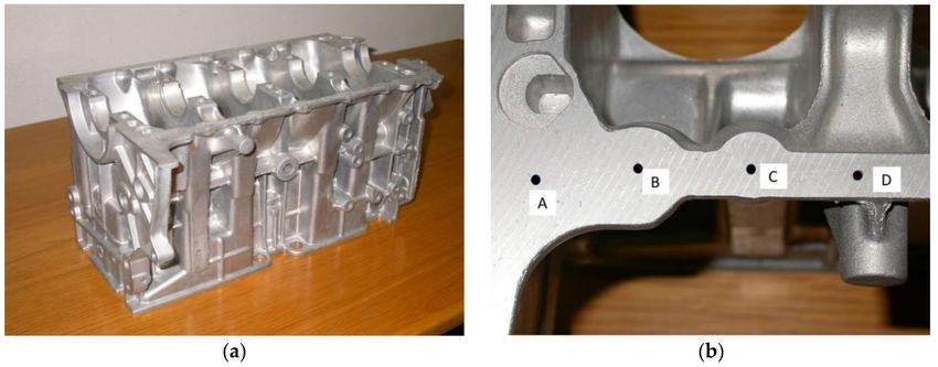
Materials 2021, 14, 1742                                                                                                     3 of 19

                                     the frictionless indentation of an elastic half-space by a flat-ended cylindrical punch, and
                                     the contact area is assumed to be equal to the indenter tip area of radius R. The boundary
                                     conditions in the local system r-z (Figure 1) can be expressed as

                                                                           σz (r,0) = 0             r>R
                                                                          τ rz (r,0) = 0          0≤r≤R                         (1)
                                                                          uz (r,0) = h            0≤r≤R

                                          No normal stress σz acts on the free surface outside the contact region (first condi-
                                     tion); there is no friction between indenter surface and half space (second condition); the
                                     displacement uz in z direction is consistent with the flat end of the punch (third condition).

                                     Figure 1. Schematic view of indentation by a flat-ended punch.

                                         The punch has a sharp edge thus σz → ∞ when r = R and localized plastic deformation
                                     occurs on the circular edge [27]. Owing to the constant contact area, the relationship
                                     between the mean contact pressure Pm and the penetration depth h is linear and given by:

                                                                                          2Eh
                                                                              Pm =                  ,                           (2)
                                                                                       πR(1 − υ 2 )

                                      E being the Young’s modulus, and υ the Poisson’s ratio.
                                           According to the Sneddon’s solution [26,28], the stress field in the elastic half-space
                                      can be expressed in the (r, θ, z) cylindrical coordinate system by the following equations:
                                       nh              i      h           i      h                  i        o
                                              d2                1+K sin Φ
                                                2 − dz arctan z +K cos Φ − r2 (1 − 2ν ) + z dz (1 − K sin Φ ) ,
                                                     d                                            d
                           σr = − 12 Pm −z dz                                  1

                                                                         h           i
                                              σϑ = Pm (1 + ν) dzd
                                                                  arctan z1++K sin Φ − σ − σ ,
                                                                             K cos Φ       r    z
                                                             h 2         i        h           i                                 (3)
                                                                d      d            1+K sin Φ
                                                 σz = − 12 Pm z dz 2 − dz arctan z+K cos Φ ,

                                                                      2
                                                     τrz = − 12 Pm zr dz2 (1 − K sin Φ ),
                                                                      d

                                     where R is assumed to be equal to 1, K4 = (r2 + z2 − 1) + 4z2 and

                                                                                                  2z
                                                                             tan(2Φ) =
                                                                                            r2   + z2 − 1
                                          If plasticity is included in the indentation model, the constitutive equations are not
                                     linear and involve some parameters of the material (yield stress and work-hardening
                                     coefficient) for studying its plastic behavior. Different approaches have been used to
                                     describe the stress–strain field induced during indentation by punches of different shapes;
                                     the spherical cavity [29] and the slip-line field [30] models are the most relevant ones.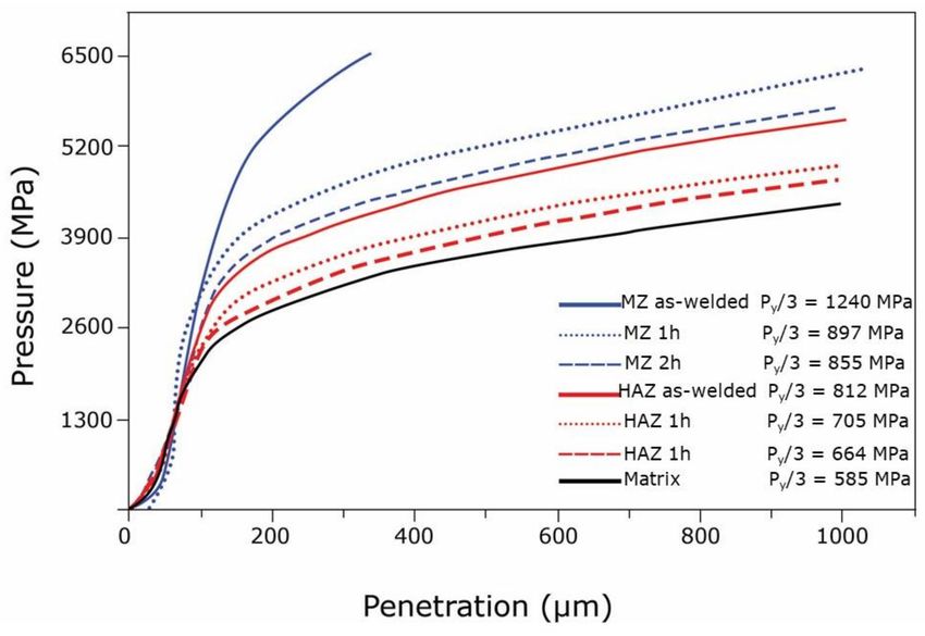
Materials 2021, 14, 1742                                                                                              4 of 19

                                 Under the condition that the material follows the Tresca plasticity criterion, Shield [31]
                           showed that the axisymmetric plastic flow of a rigid-plastic material can be described by
                           a slip line field and determined the stress field for the indentation of a semi-infinite solid
                           by a flat-ended cylindrical punch. The mean contact pressure Pm was estimated to be 5.69
                           ξ (ξ is the shear strength of the material); the maximum contact pressure Pmax (close to
                           punch edge) is 7.2 ξ; and the radial extension of the plastic area is 1.58 R. A further work
                           of Eason and Shield [32] demonstrated that plastic deformation starts at punch edge, and
                           then it progressively extends with penetration depth and reaches the indenter axis when
                           Pm is about six times the shear strength, namely, three times the tensile yield stress σY , as a
                           consequence of the Tresca plasticity criterion.
                                 The FIMEC apparatus was designed and realized at the beginning of 90s, and the first
                           results were published in 1994 [1]. At that time cylindrical indentation was not as popular
                           as it is today. In addition to the aforesaid theoretical studies, the work of Yu et al. [33] was
                           of particular importance for developing the technique. These investigators determined
                           some empirical formulae differentiating the load–penetration curve from a conventional
                           compression test. Then the effects of the round corners of a flat punch in an elastic–plastic
                           field were investigated by Ciavarella et al. [34]. Scibetta et al. [35] analyzed data from
                           experiments on several materials through a simplified formula that gives the constraint
                           factor as a function of the hardening exponent and the limit value determined by Shield
                           for rigid–plastic materials.
                                 The flat indentation of metals was investigated by us through experimental tests
                           and FEM providing an interpolation formula for the load–penetration relationship [6].
                           Such work was further developed, and a new equation has been derived to calculate
                           the yield stress from the experimental data in deep indentation [36]. Across 25 of years
                           activity, a lot of experimental data have been collected on various metals and alloys which
                           support this approach. Recently, some of these data were used by Brutti [37] to validate
                           a new theoretical model that allows one to solve the direct and the inverse problems of
                           flat indentation. Moreover, FIMEC test has been successfully used in different industrial
                           applications; some examples of case studies are reported in this paper.
                                 A typical curve obtained from FIMEC test is displayed in Figure 2. After an initial
                           elastic stage up to a pressure PL , three plastic stages are observed: (i) the first one is nearly
                           linear and ends at PY ; the second one starts when the plastic deformation reaches the
                           indenter axis (P > PY ) and exhibits a curve slope decrease; the third stage has a trend with
                           an almost constant slope. More details are reported in ref. [6]. On these grounds, it is
                           possible to directly compare data from FIMEC indentation and tensile tests: the yield stress
                           σY is approximately equal to PY /3. This is confirmed by a lot of experimental evidence,
                           e.g., Figure 3 displays PY /3 vs. σY data of different metals and alloys, and all the points lie
                           close to the bisector line.
                                 The relationship σY = PY /3, which is analogous to the findings of Eason and Shield [32]
                           theoretical work, has been assessed to be valid by testing different pure metals and alloys
                           also at high and low temperature [6]. Of course, the critical point is the accurate determina-
                           tion of the point PY in the load–penetration FIMEC curve from which the yield stress σY is
                           then calculated. In the second and third stages, P can be described by a relationship similar
                           to that often used for modelling stress-strain curves:

                                                                   P = K (h0 + h)n                                       (4)

                           where K and h0 are constants, n the strain-hardening exponent. Equation (4) allows one
                           to fit the FIMEC curves in the secnd and third stages and determine the point PY . The
                           method has been described in detail in [36], and the results show that the relative difference
                           between PY /3 and σY obtained in tensile tests does not exceed ±7%, namely, the σY data
                           scattering resulting from tensile tests on the same material [38].
                                 An experimental parameter in FIMEC tests that must be properly chosen is the inden-
                           tation rate because it affects the trend of pressure–penetration curves [1]. The relationship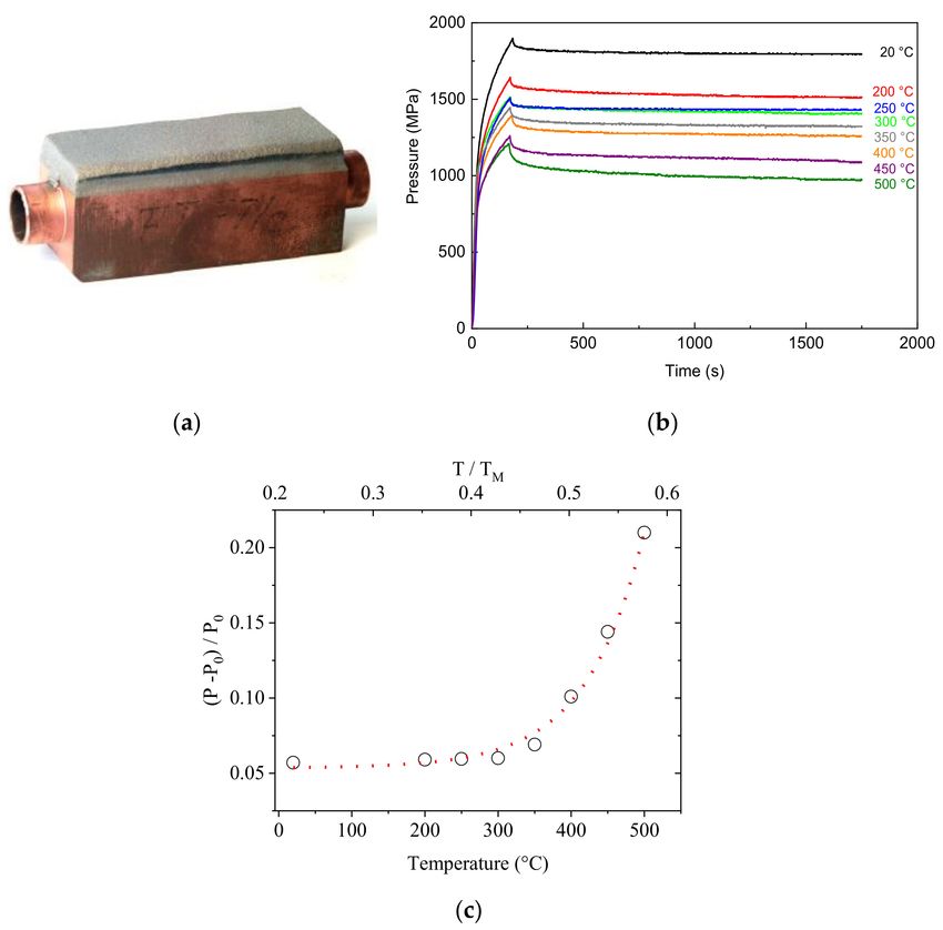
Materials 2021, 14, 1742                                                                                                    5 of 19

                           σY = PY /3 is applicable only in the case that the indentation tests are carried out with a
                           penetration rate of 0.1 mm/min or lower [6].
                               FIMEC tests can be made by employing punches of diameter in the range 0.5–1 mm de-
                           pending on the characteristics of the mechanical parts to examine; the pressure–penetration
                           curves obtained by testing the same material show an almost perfect overlapping [5].

                           Figure 2. Flat-top cylinder indenter for mechanical characterisation (FIMEC) indentation curve of
                           25Cr4Mo steel.

                           Figure 3. PY /3 from FIMEC test are plotted vs. σY data from tensile tests of different metals and
                           alloys. All the points are close to the bisector line showing that σY is approximatively equal to PY /3.

                                Recently, the large use of small components in many industrial fields stimulated
                           the research on test methods employing indenters of very small size; however, such
                           effort encountered a serious problem first evidenced by Nix and Gao [39]: the measured
                           hardness of a material has been found to increase as the size of the indenter decreases.
                           The phenomenon has been termed indentation size effect (ISE). Campbell and Gill [40]
                           proposed a model for flat indentation taking into account ISE that reproduces the force–
                           displacement loading and unloading response of flat punches of different widths. Their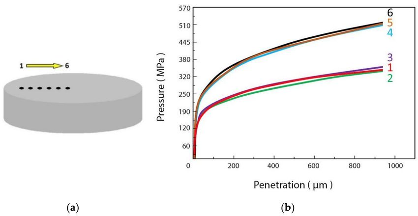
Materials 2021, 14, 1742                                                                                                        6 of 19

                                  model shows good agreement with experimental data (e.g., [41]) and has the following main
                                  characteristics: (i) the contact pressure depends on two length scales (punch width and
                                  indentation depth); (ii) shape and connectivity of the plastic zones change with indentation
                                  depth and punch width; (iii) the proportion of the deformation accommodated by elasticity
                                  and plasticity changes.

                                  3. Case Studies
                                  3.1. Crank Manufacturing through Pin Squeeze Casting
                                       Pressure die casting is a common manufacturing process used in many industrial
                                  sectors, in particular those with strong automation such as the automotive one. Today,
                                  manufacturers tend to produce components by using increasingly higher pressures with the
                                  scope to increase the size of components and reduce the residual porosity. Pressure increase
                                  involves higher cooling rates of castings that lead to thermal gradients and shape distortion
                                  of the manufactured components. Therefore, the industrial process where castings are
                                  submitted to the highest pressures (squeeze casting) is still a niche process. An intermediate
                                  solution between squeeze casting and die casting is pin squeeze casting where the highest
                                  pressure is applied only in some areas of the components through small pins before the
                                  complete solidification of casting when the material is semi-solid.
                                       In the case considered here, pin squeeze casting has been employed for improving the
                                  mechanical properties of cranks of small size made of the aluminum EN-AB46000 alloy
                                  and used in compressors of domestic refrigerators. In order to establish the optimal process
                                  conditions, the knowledge of local mechanical properties of cranks was of the utmost
                                  importance, in particular in the zones subjected to the higher stresses in service life (point 1
                                  in Figure 4a).
                                       FIMEC tests were performed in these points of cranks produced with and without
                                  local pressure (110 bar) of the pin. The additional pin pressure has been applied on the
                                  opposite side of that subjected to FIMEC indentation test; the measured values of yield
                                  stress are displayed in Figure 4b.
                                       The local pin pressure has two remarkable effects. The first effect is to increase the
                                  yield stress in the whole crank (also in point 2 far from the zone where pin pressure is
                                  applied) to values which cannot be reached in the ordinary die casting process. The second
                                  one consists of the change of the local mechanical properties: in the crank produced without
                                  the pin pressure the yield stress is higher in point 2 than in point 1, whereas the contrary
                                  occurs if additional pin pressure is applied in point 1 during the process. This is very
                                  important because pin squeeze casting guarantees the best mechanical properties in the
                                  zone of the crank that is subjected to the highest stress in exercise.

      Figure 4. Yield stress determined through FIMEC test in the points 1 and 2 of the crank (a) produced with and without local
      pressure of the pin in the point 1 (b).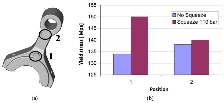
Materials 2021, 14, 1742                                                                                                     7 of 19

                                 3.2. Evaluation of the Local Mechanical Properties in a Carter of Complex Geometry
                                       Components of a complex shape are commonly produced through foundry processes
                                 and non-homogeneous cooling rates often give rise to different local mechanical charac-
                                 teristics in different zones of the same piece. The case presented here is that of a carter
                                 (Figure 5a) made in aluminum EN-AB46100 alloy. About one hundred FIMEC tests have
                                 been performed in different areas of the carter (e.g., see Figure 5b) to determine the local
                                 yield stress, and on this basis the die sections have been suitably modified to obtain more
                                 homogeneous mechanical properties.

      Figure 5. Carter in EN-AB46100 alloy (a). Several FIMEC tests have been performed in different positions (A, B, C, D) of
      this mechanical component to evaluate the local mechanical properties (b).

                                       To perform such measurements the experimental apparatus has been modified due to
                                 the great size of the tested component. The standard FIMEC apparatus operates through a
                                 linear actuator (an electro-mechanical drive equipped with a step motor) [6]. The motor
                                 rotation is transmitted to a ball screw that converts rotation into translation, guided by
                                 means of a pre-loaded ballspline, and the indenter is mounted at the end of a rod while the
                                 load cell is allocated under the sample holder. For carrying out these measures, the load
                                 cell has been mounted between the linear actuator and the tested piece.

                                 3.3. Qualification of Aluminium Billets for Extrusion
                                       In manufacturing mechanical parts by extrusion, the control of process parameters
                                 (applied stress and deformation rate) is of the utmost importance to obtain products with
                                 standard and reproducible characteristics. A problem often encountered by forgers is
                                 connected to the quality and properties of the billets which are commonly provided by
                                 different suppliers. Billets of the same material with controlled chemical composition may
                                 give rise to quite different extruded products if the microstructure is different, in particular
                                 the size and orientation of crystalline grains along the billet thickness plays a critical role.
                                 Therefore, the mechanical properties of the billets should be assessed before extrusion to
                                 avoid manufacturing rejects and higher costs.
                                       The FIMEC test has revealed to be a technique that guarantees a fast response and
                                 sound results in testing the billets to be employed in the extrusion process. It allows one to
                                 obtain a map of yield stress along the thickness of the billet and is helpful in the choice of
                                 suitable process parameters.
                                       For example, Figure 6a displays the section of a billet and the positions where in-
                                 dentation tests have been performed; the pressure-indentation depth curves in (b) clearly
                                 show that the mechanical properties change along the radial direction. Once the optimal
                                 characteristics for extrusion under standard work parameters have been identified, FIMEC
                                 tests allow one to check whether a given billet stock is suitable to be processed.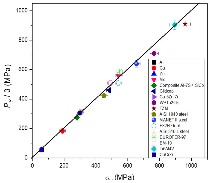
Materials 2021, 14, 1742                                                                                                       8 of 19

      Figure 6. Schematic view of a section of an aluminium billet where FIMEC tests were performed in different positions along
      the radial direction (a). The pressure–penetration depth curves are displayed in (b).

                                 3.4. Stress-Relaxation Tests on CuCrZr Heat Sinks
                                       The CuCrZr copper alloy is a promising material for high heat flux applications in
                                 future fusion reactors such as the International Thermonuclear Experimental Reactor (ITER),
                                 in particular for manufacturing heat sinks which are commonly protected from plasma by
                                 W armors. For example, Figure 7a displays a component with a thick W coating on one face.
                                 During a long-term operation, thermal creep and stress relaxation cause permanent damage
                                 to the material at elevated temperature and stress levels below the yield point; thus, these
                                 phenomena have been extensively investigated (e.g., see ref. [42–45]).
                                       The FIMEC indentation test has been used by us to investigate stress relaxation at
                                 different temperatures up to 500 ◦ C, namely, above those foreseen in exercise (≈300 ◦ C).
                                 The scope was to identify the critical temperature above which stress relaxation represents
                                 a serious problem for the components.
                                       The examined alloy was supplied by Outokumpu (Jyväskylä, Finland) and had the
                                 following composition: Cr 0.73, Zr 0.14, Cu to balance (wt%). The stress–relaxation tests
                                 have been carried out by stopping the penetration and recording the evolution of stress
                                 vs. time, while the penetration depth was kept constant. The curves obtained in tests at
                                 increasing temperature are reported in Figure 6b. After an initial drop, the stress exhibits
                                 an exponential trend which can be described by the following relationship:

                                                                            P = P0 e−t/τ                                           (5)

                                        Relaxation consists of the progressive transformation of elastic deformation into plastic
                                 deformation thus, since the sum of elastic and plastic deformation is constant, the measured
                                 stress P decreases. Data in Figure 7b clearly show a strong test temperature dependence.
                                 The relative variation of the stress P with respect the initial value P0 , (P − P0 )/P0 , after
                                 1750 s is reported in Figure 7c and shows how there is a significant increase when tempera-
                                 ture exceeds 0.45 TM (TM is the melting point) corresponding to about 330 ◦ C, when the
                                 typical mechanisms of high temperature deformation (climb and dislocation cross-slip)
                                 become active. The result evidences how the critical temperature for stress relaxation is just
                                 a little above the maximum one foreseen in service for CuCrZr components; therefore, great
                                 attention should be paid to the temperature fluctuations involved in a system operating in
                                 pulsed mode.
Materials 2021, 14, 1742 9 of 19
Figure 7. FIMEC stress relaxation tests on CuCrZr alloy: heat sink (a); pressure vs. time curves at increasing temperatures
(b); relative variation of the stress P with respect the initial value P0 , −P − P0 )/P0 , after 1750 s (c).
3.5. Characterization of Thick W Coatings on CuCrZr Alloy
As mentioned in the previous section, W is the first-choice material to protect structural
components, divertor and cooling systems in future nuclear fusion reactors because of its
excellent thermo-mechanical proprieties, high melting point, high thermal conductivity,
low physical sputtering, tritium retention, and activation under neutron irradiation [46–48].
An option is the use of bulk W tiles; however, the poor W machinability is a serious
drawback for realizing parts of complex geometry, e.g., those for protecting tubes and pipe
fittings of the cooling system. An alternative solution is the deposition of thick coatings on
such components commonly made of the CuCrZr alloy. Joining is a hard task for the high
thermal expansion mismatch between and CuCrZr (αCu ≈ 4αW ), leading to high residual
stresses with the possible formation and propagation of cracks and final detachment of the
coating. Therefore, a lot of coating technologies have been examined to find the suitable
ones, and the attention has been focused on plasma spray (PS) in vacuum or controlled
atmosphere [49,50] for its simplicity, low costs, and the possibility to cover large surfaces.
W coatings (5 mm-thick) on CuCrZr substrates have been realized by means of PS in
controlled atmosphere by Riccardi et al. [51,52], and they were able to withstand heat fluxes
up to 5 MW/m2 . An interlayer with thickness of about 800 µm was deposited between
substrate and coating with intermediate thermal expansion coefficient; it consisted of a
layer of pure Ni and a successive stratification of layers of grading mixtures of Al–12%,
Si, and Ni–20% Al. Figure 8a shows the complex morphology of the interface and the
presence of some porosity and unmolten particles which may represent preferred sitesMaterials 2021, 14, 1742 10 of 19
for crack nucleation. As displayed in the fractographic image of Figure 8b, the grains of
the W coating exhibit a columnar structure which involves strong anisotropic mechanical
properties. These characteristics have been investigated through FIMEC indentation tests.
Figure 8. Morphology of the W-CuCrZr interface (a); fracture surface of plasma sprayed W showing the structure with
columnar grains (b) [51].
Figure 9a displays the FIMEC curves obtained by indenting the W coating along the
direction perpendicular to the surface at increasing temperature up to 500 ◦ C [52]. Even if
some curves (e.g., at 200 and 300 ◦ C) exhibit pop-ins due to the formation of small cracks
during punch penetration, in general the material has a good resistance. The values of
yield stress are reported in Table 1.
On the contrary, when indentation is carried out along the direction parallel to the
coating surface, long cracks form at the beginning of the penetration test inducing a
pressure drop. The curves obtained in the room temperature tests by indenting the W
coating along the two directions (perpendicular and parallel) are compared in the frame of
Figure 9a, while a long crack induced by parallel indentation is shown in Figure 9b. The
results indicate a strong anisotropic mechanical behavior of the coating strictly connected
to the columnar growth of W grains during deposition.
To overcome such drawback, a different approach has been investigated in the last
years, i.e., the realization of the interlayer as a functionally graded material obtained
by depositing successive layers with varying fractions of Cu and W, i.e., the W content
progressively decreases with the distance x from the pure W coating [53]. The volume
fraction VW of W in the graded layers is expressed by
x p
VW = 1 − ( ) (6)
t
t being the thickness, and p the gradient index. An actively water-cooled mock-up designed
by using such approach showed compressive and homogeneously distributed stresses in
the interlayers under operational conditions.Materials 2021, 14, 1742 11 of 19
Figure 9. FIMEC curves obtained by indenting the W coating along the direction perpendicular to the surface at increasing
temperatures up to 500 ◦ C (a). In the frame, the curves obtained in room temperature tests by indenting along perpendicular
and parallel directions are compared. A long crack induced by parallel indentation is shown in (b) [52].
Table 1. PY /3 values obtained from FIMEC tests at different temperatures.
Temperature (◦ C) 25 100 200 300 400 500
PY /3 (MPa) 794 615 575 488 425 410
3.6. Measure of the Local Mechanical Properties of the MZ and the HAZ in Welded Joints
The quality of welded joints is commonly investigated in the industrial practice
through tensile, bending, and micro-hardness tests. Although these techniques are quite
useful, they have some limits. Tensile and bending tests carried out on probes with a
welded joint provide information on the average behavior of the material but not on the
specific mechanical characteristics of the MZ and HAZ, which are of great relevance for
optimizing the post-welding heat treatments (PWHT). Moreover, bending tests do not
always help in revealing an inadequate structure in the whole welding bead, since the
maximum stress is mainly concentrated in the MZ. Micro-hardness profiles across the joints
give the local properties of the MZ and HAZ, but data are often quite scattered because
they are strongly affected by the specific tested area of the order of tens of microns. The
FIMEC test allows one to measure the yield stress in the MZ and HAZ of joints realized
through common welding processes such as MIG and TIG, while it is not suitable in the
case of electron beam and laser welds because the seams are too thin, smaller than the
indenter size. Moreover, since FIMEC imprint involves a large number of grains, the results
are representative of the average behavior of the investigated MZ and HAZ. Therefore, it
has been often used to investigate the evolution of local properties in the MZ and HAZ
of welds of steels [9,10,54] and light alloys [8] before and after PWHTs to find the best
treatment conditions.
The first example presented here regards Gas Tungsten Arc Welding (GTAW) of the
martensitic stainless steel Eurofer-97 whose composition is reported in Table 2.Materials 2021, 14, 1742 12 of 19
Table 2. Nominal chemical composition of Eurofer-97 steel (wt%).
Cr C Si Mn P S Mo W V Ta Ti N
8.87 0.10 0.05 0.45 0.005 0.004 0.0027 1.15 0.20 0.14 0.005 0.017
Ni Cu Co Al Nb B O As Sn Zr Sb Fe
0.028 0.0035 0.006 0.008 0.0025Materials 2021, 14, 1742 13 of 19
Figure 10. Gas tungsten arc welding (GTAW) joints of Eurofer-97 steel. FIMEC curves obtained from
base metal, the HAZ, and the MZ in as-welded condition and after post-welding heat treatments
(PWHTs) of 1 and 2 h at 750 ◦ C.
Figure 11. Local microstructure of the joint in areas close to the positions where 15 FIMEC indentation tests were performed
(yellow). For each position, the PY /3 values determined from FIMEC tests are reported (white).
Table 4 reports the PY /3 values determined by FIMEC tests and the average micro-
hardness HV measured in the same positions.Materials 2021, 14, 1742 14 of 19
Table 4. Micro-hardness HV and PY /3 values determined by means of FIMEC tests in the positions
shown in Figure 11. The HV/PY /3 ratio is also shown.
Point 1 2 3 4 5 6 7
Zone HAZ HAZ MZ HAZ HAZ MZ HAZ
PY /3 607 637 628 637 607 662 620
HV 278 275 284 274 289 290 285
HV/ PY /3 0.46 0.43 0.45 0.43 0.48 0.44 0.46
Point 8 9 10 11 12 13 14 A
Zone MZ MZ HAZ MZ MZ MZ MZ BM
PY /3 670 594 599 616 658 594 637 594
HV 290 289 256 275 280 279 283 256
HV/ PY /3 0.43 0.48 0.43 0.44 0.43 0.47 0.44 0.43
The base metal (point A) exhibits grains of austenite (brighter) and ferrite (darker),
whereas in the MZ also grains of austenite with Widmanstätten morphology are observed.
The yield stress and micro-hardness variations depend on the microstructural changes
observed in the investigated positions. In fact, different heat fluxes in MF and HAZ
determine a change of the relative fraction of ferrite and austenite, which affects the
local mechanical properties. In general micro-hardness and FIMEC values show a good
correspondence because the HV/PY /3 ratio lies in a narrow range (0.43–0.48); however,
micro-hardness data are more scattered because each imprint is made either in an austenite
grain or in a ferrite grain, whereas many grains of both phases are involved in a single
FIMEC test.
An important microstructural aspect that can lead to the relevant variations of me-
chanical properties in welded duplex stainless steels (DSS) is the precipitation of second
phases (SP). This represents a critical issue for industrial processes; therefore, a specific
work has been carried out to assess whether data from FIMEC tests can be somehow
correlated to SPs precipitation and provide indirect information about such microstructural
features. The material used in the experiments was the 2205 steel, one of the most used
DSS for applications in the pulp and paper, chemical processing, refining, petrochemical,
food and beverage, and transportation industries. The examined material was supplied
by Sandmeyer Steel Co (Philadelphia, PA, USA), and its nominal composition is given in
Table 5.
Table 5. Nominal chemical composition of the 2205 steel (wt%).
C Cr Mn Mo N Ni Si P S FeMaterials 2021, 14, 1742 15 of 19
lower temperatures (750 ◦ C) it grows in the “coral-like” morphology (Figure 12b). Another
intermetallic compound coexisting with σ phase is the χ phase (Figure 12c) that forms at
750 ◦ C, even if in smaller amounts than σ phase [53,59]. The χ particle shown in Figure 12c
nucleated at a α/α boundary and the inset shows the crystallographic relationship between
the χ and α phases. Nitrides and M23 C6 carbides were also observed in all of the examined
samples, but their volume fractions are very small with respect to the other SPs. In fact,
microstructural examinations showed that σ phase represents the largest part of SPs present
in the steel after all the heat treatments.
Figure 12. Morphological features of second phases (SPs) in 2205 steel. The σ phase morphology is “oil spot” (a) or
“coral-like” (b) depending on precipitation temperature. The micrograph in (c) shows the χ phase and is taken from ref. [54].
From: “Flat-top cylinder indenter examination of duplex stainless steel 2205 after different heat treatments” by G. Angella,
A. Fava, R. Montanari, M. Richetta, A. Varone, 2017, Metals.
Figure 13 displays the PY /3 values determined from FIMEC tests vs. the total volume
fraction of SPs developed after heat treatments at 750, 850, and 900 ◦ C.
By comparing these data with the yield stress of as-supplied material (PY /3 = 470 MPa),
it is clear that FIMEC allows one to reveal very small amounts of SPs (1–2%). The achievement
appears of great relevance if one considers that such volume fractions have negligible effect
on ultimate tensile strength, and Young’s modulus [59] and conventional hardness tests are
not considered reliable for revealing quantities of SPs below ≈ 4% [60–62]. For industrial
applications, the importance of detecting such low amounts of SPs can be well understood by
considering that the impact value of 2205 steel drops by about 50% in comparison with the
original one (solution annealed and quenched steel) in the presence of ~1% of σ phase [63].
As expected, yield stress increases with the volume fraction of SPs; however, Figure 13
gives also other important information: the same amounts of SPs developed through heat
treatments at 700, 850, and 900 ◦ C correspond to different PY /3 values. Specifically, the
lower the temperature, the higher the yield stress. For example, a total SP amount of
10–11% gives rise to a yield stress of 672 MPa if the steel is treated at 750 ◦ C, whereas in the
case of treatment at 900 ◦ C the value of PY /3 is 622 MPa, i.e., 50 MPa lower. Such difference
has to be ascribed mainly to the morphology of the σ phase, “coral-like” at 750 ◦ C and
“oil spot” at the higher temperatures considered in these experiments. This is consistent
with the well-known behavior of DSSs which exhibit more brittle behavior after lower
temperature precipitation [64] because in presence of the “coral-like” structure of the σ
phase, even small strains lead to transcrystalline cracks with consequent toughness loss.
In conclusion, FIMEC allows one to reveal the precipitation of small SP amounts (~1%)
not detectable through other mechanical tests and is also sensitive to the specific σ phase
morphology (“coral-like” or “oil spot”); thus, it is a suitable technique for assessing in
industrial practice the state of DSS after temperature exposure and the quality of welds.Materials 2021, 14, 1742 16 of 19
Figure 13. PY /3 values determined from the FIMEC tests vs. total volume fraction of SPs formed
after heat treatments at 750, 850, and 900 ◦ C. Redrawn from ref. [54].
4. Conclusions
The work reported some case studies where the FIMEC test has been successfully
used to solve industrial problems regarding different metals and alloys. The results demon-
strate its great versatility and capability to give information not available by employing
conventional experimental techniques such as tensile, bending, and hardness tests.
The plastic behavior of a material under the penetration of a flat-ended indenter is
today fully understood, and the theory gives an exhaustive description of its response in
terms of stress vs. penetration depth, also taking into account the indentation size effect
(ISE) phenomenon.
On these grounds, the FIMEC indentation test, which was originally developed for
investigating the mechanical properties of irradiated materials, has proved to be a mature
technique for a use on a large scale in industrial practice.
Author Contributions: Roberto Montanari and Alessandra Varone wrote the paper. All authors have
read and agreed to the published version of the manuscript.
Funding: This research received no external funding.
Institutional Review Board Statement: Not applicable.
Informed Consent Statement: Not applicable.
Data Availability Statement: The data presented in this study are available on request from the
corresponding author.
Conflicts of Interest: The author declares no conflict of interest.
Nomenclature
R indenter tip radius
r distance from the center of cylindrical indenter
h indenter penetration depth
σz normal stress in z directionMaterials 2021, 14, 1742 17 of 19
τrz shear stress in the rz plane
uz displacement in z direction
Pm mean contact pressure
Pmax maximum contact pressure
E Young’s modulus
ν Poisson’s ratio
(r, θ, z) local cylindrical coordinate system
σr normal stress in r direction
σθ normal stress in θ direction
ξ shear strength
Py upper limit of the first plastic stage of the experimental pressure-penetration curve
σy yield stress
P0 initial pressure in stress relaxation tests
t time
τ relaxation time in stress relaxation tests
FIMEC Flat top Indenter for Mechanical Characterization
IFMIF International Fusion Materials Irradiation Facility
CFRP Carbon Fiber Reinforced Polymer
DBTT ductile to brittle transition temperature
CRB cracked Round Bar
ISE indentation size effect
PS plasma spray
VW volume fraction of W in the graded layers between CuCrZr substrate and pure W coating
x distance from the pure W coating
t interlayer thickness
p gradient index
TIG tungsten inert gas
MIG metal-arc inert gas
GTAW gas tungsten arc welding
HAZ heat affected zone
MZ molten zone
PWHT post welding heat treatment
TBM Test Blanket Module of ITER
ITER International Thermonuclear Experimental Reactor
DSS duplex stainless steel
SP second phase
SEM scanning electron microscopy
TEM transmission electron microscopy
References
1. Gondi, P.; Montanari, R.; Sili, A. Small scale non-destructive stress-strain and creep tests feasible during irradiation. J. Nucl. Mater
1994, 212–215, 1688–1692. [CrossRef]
2. Gondi, P.; Donato, A.; Montanari, R.; Sili, A. A miniaturized test method for the mechanical characterization of structural
materials for fusion reactors. J. Nucl. Mater. 1996, 233–237, 1557–1560. [CrossRef]
3. Gondi, P.; Montanari, R.; Sili, A.; Foglietta, S.; Donato, A.; Filacchioni, G. Applicability of the FIMEC indentation test to
characterize materials irradiated in the future IFMIF high intensity neutron irradiation source. Fusion Technol. 1996, 1607.
Available online: http://hdl.handle.net/2108/50374 (accessed on 16 March 2021).
4. Donato, A.; Gondi, P.; Montanari, R.; Moreschi, L.; Sili, A.; Storai, S. A remotely operated FIMEC apparatus for the mechanical
characterization of neutron irradiated materials. J. Nucl. Mater. 1998, 258–263, 446–451. [CrossRef]
5. Riccardi, B.; Montanari, R.; Moreschi, L.F.; Sili, A.; Storai, S. Mechanical characterization of fusion materials by indentation test.
Fusion Eng. Des. 2001, 58–59, 755–759. [CrossRef]
6. Riccardi, B.; Montanari, R. Indentation of metals by a flat-ended cylindrical punch. Mater. Sci. Eng. A 2004, 381, 281–291.
[CrossRef]
7. Montanari, R.; Filacchioni, G.; Iacovone, B.; Plini, P.; Riccardi, B. High temperature indentation tests on fusion reactor candidate
materials. J. Nucl. Mater. 2007, 367–370, 648–652. [CrossRef]
8. Missori, S.; Montanari, R.; Sili, A. Caratterizzazione meccanica mediante prove FIMEC di giunti saldati in lega Al 6082. La Metall.
Ital. 2001, 3, 35.Materials 2021, 14, 1742 18 of 19
9. Filacchioni, G.; Montanari, R.; Tata, M.; Pilloni, L. Structural and mechanical properties of welded joints of reduced activation
martensitic steels. J. Nucl. Mater. 2002, 307–311, 1563–1567. [CrossRef]
10. Montanari, R.; Filacchioni, G.; Riccardi, B.; Tata, M.E.; Costanza, G. Characterization of eurofer-97 TIG-welded joints by FIMEC
indentation tests. J. Nucl. Mater. 2004, 329–333, 1529–1533. [CrossRef]
11. Yang, F.; Li, J.C.M. Impression test—A review. Mater. Sci. Eng. R 2013, 74, 233–253. [CrossRef]
12. Lu, Y.C.; Kurapati, S.N.V.R.K.; Yang, F. Finite element analysis of cylindrical indentation for determining plastic properties of
materials in small volumes. J. Phys. D Appl. Phys. 2008, 41, 115415. [CrossRef]
13. Casamichele, L.; Quadrini, F.; Tagliaferri, V. Non-destructive evaluation of local mechanical properties of Al die cast large
components by means of FIMEC indentation test. Measurement 2007, 40, 892–897. [CrossRef]
14. Genna, S.; Trovalusci, F.; Tagliaferri, V. Indentation test to study the moisture absorption effect on CFRP composite. Compos. Part
B Eng. 2017, 124, 1–8. [CrossRef]
15. David, F.; Moretti, P.; Tagliaferri, V.; Trovalusci, F. FIMEC test to evaluate the water uptake of coated and uncoated CFRP
composites. Materials 2020, 13, 1154. [CrossRef]
16. Xu, B.; Wang, X.; Zhao, B.; Yue, Z. Study of crystallographic creep parameters of nickel-based single crystal superalloys by
indentation method. Mater. Sci. Eng. A 2008, 478, 187–194. [CrossRef]
17. Midawi, A.R.H.; Huda, N.; Simha, C.H.M.; Gerlich, A.P. Characterization of anisotropy of strength in API-X80 line pipe welds
through instrumented indentation. Met. Microstruct. Anal. 2020, 9, 884–894. [CrossRef]
18. Kim, W.; Choi, S.; Kim, J.; Jeon, S.-W.; Choi, M.-J.; Kwon, D. Estimation of fracture toughness using flat-ended cylindrical
indentation. Met. Mater. Int. 2020, 1–9. [CrossRef]
19. Ozcan, S.; Tezcan, J.; Gurung, B.; Filip, P. The effect of heat treatment temperature on the interfacial shear strength of C/C
composites. J. Mater. Sci. 2011, 46, 38–46. [CrossRef]
20. Mohammed, A.S.K.; Sehitoglu, H.; Rateick, R. Interface graphitization of carbon-carbon composites by nanoindentation. Carbon
2019, 150, 425–435. [CrossRef]
21. Brezmes, A.O.; Breitkopf, C. Influence of indenter tip diameter and film thickness on flat indentations into elastic-plastic films by
means of the finite element method. Thin Solid Films 2018, 653, 49–56. [CrossRef]
22. Hertz, H. Uber die Beruhrung fester Elastischer Korper (on the contact of elastic solids). Reine Angew. Math. 1882, 92, 156–171.
23. Cerruti, V. Memorie di Fisica Matematica; Accademia dei Lincei: Roma, Italy, 1882.
24. Boussinesq, J. Application des Potentiels a l’Etude de l’Equilibre et du Mouvement de Solides Elastiques; Gautier-Villar: Paris, France,
1885.
25. Love, A.E.H. A Treatise on the Mathematical Theory of Elasticity, 4th ed.; Dover: New York, NY, USA, 1944.
26. Sneddon, I.N. The relation between load and penetration in the axisymmetric boussinesq problem for a punch of arbitrary profile.
Int. J. Eng. Sci. 1965, 3, 47–57. [CrossRef]
27. Timoshenko, S.; Godier, J.N. Theory of Elasticity, 3rd ed.; Mc Graw Hill: New York, NY, USA, 1951; p. 408.
28. Tranter, C.J.; Sneddon, I.N. Fourier transforms. Math. Gaz. 1952, 36, 290. [CrossRef]
29. Bishop, R.F.; Hill, R.; Mott, N.F. The Theory of Indentation and Hardness Tests. In Proceedings of the Physical Society; IOP Publishing:
Bristol, UK, 1945; Volume 57, pp. 147–159.
30. Johnson, K.L. Contact Mechanics; Cambridge University Press: Cambridge, UK, 1985; pp. 153–201.
31. Shield, R.T. On the plastic flow of metals under conditions of axial symmetry. Proc. R. Soc. A 1955, 233, 267–287.
32. Eason, G.; Shield, R.T. The plastic indentation of a semi-infinite solid by a perfectly rough circular punch. Z. Angew. Math. Phys.
1960, 11, 33–43. [CrossRef]
33. Yu, H.Y.; Imam, M.A.; Rath, B.B. Study of the deformation behavior of homogeneous materials by impression tests. J. Mater. Sci.
1985, 20, 636–642. [CrossRef]
34. Ciavarella, M.; Hills, D.A.; Monno, G. The influence of rounded edges on indentation by a flat punch. Proc. Instn. Mech. Eng.
1998, 212, 319–328. [CrossRef]
35. Scibetta, E.; Lucon, R.; Chaouadi, E.; Walle, W. Instrumented hardness testing using a flat punch. Int. J. Pres. Ves. Pip. 2003, 80,
345–349. [CrossRef]
36. Ciambella, L.; Montanari, R. New algorithm to determine the yield stress from FIMEC test. Mater. Sci. Forum 2014, 783–786,
2272–2277. [CrossRef]
37. Brutti, C. A theoretical model for elastic-perfectly plastic flat cylindrical punch indentation. Mech. Mater. 2021, 155, 103770.
[CrossRef]
38. Christ, B.W. Effect of Specimen Preparation, Setup and Test Procedures on Test Results. Metals Handbook, 9th ed.; ASM International:
Chicago, IL, USA; Volume 8, p. 32.
39. Nix, W.D.; Gao, H. Indentation size effects in crystalline materials: A law for strain gradient plasticity. J. Mech. Phys. Solids 1998,
46, 411–425. [CrossRef]
40. Campbell, C.; Gill, S. An analytical model for the flat punch indentation size effect. Int. J. Solids Struct. 2019, 171, 81–91. [CrossRef]
41. Chen, K.; Meng, W.; Mei, F.; Hiller, J.; Miller, D. From micro- to nano-scale molding of metals: Size effect during molding of single
crystal Al with rectangular strip punches. Acta Mater. 2011, 59, 1112–1120. [CrossRef]Materials 2021, 14, 1742 19 of 19
42. You, J.; Visca, E.; Bachmann, C.; Barrett, T.; Crescenzi, F.; Fursdon, M.; Greuner, H.; Guilhem, D.; Languille, P.; Li, M.; et al.
European DEMO divertor target: Operational requirements and material-design interface. Nucl. Mater. Energy 2016, 9, 171–176.
[CrossRef]
43. Mao, X.; Fursdon, M.; Chang, X.; Zhang, J.; Liu, P.; Ellwood, G.; Qian, X.; Qin, S.; Peng, X.; Barrett, T. Exploring the engineering
limit of heat flux of a W/RAFM divertor target for fusion reactors. Nucl. Fusion 2018, 58, 066014. [CrossRef]
44. Lu, K.; Liu, P.; Qian, X.; Mao, X.; Zhang, J.; Peng, X.; Qin, S.; Song, Y. Fatigue and fracture analysis on EAST divertor monoblock
heat sink in H-mode operation. Fusion Eng. Des. 2018, 137, 30–34. [CrossRef]
45. Zhang, K.; Gaganidze, E.; Gorley, M. Development of the material property handbook and database of CuCrZr. Fusion Eng. Des.
2019, 144, 148–153. [CrossRef]
46. Liu, P.; Qian, X.; Mao, X.; Song, W.; Peng, X. Study on creep-fatigue of heat sink in W/CuCrZr divertor target based on a new
approach to creep life. Nucl. Mater. Energy 2020, 25, 100846. [CrossRef]
47. Linke, J.M.; Hirai, T.; Rödig, M.; Singheiser, L.A. Performance of plasma-facing materials under intense thermal loads in tokamaks
and stellarators. Fusion Sci. Technol. 2017, 46, 142–151. [CrossRef]
48. Linke, J.; Du, J.; Loewenhoff, T.; Pintsuk, G.; Spilker, B.; Steudel, I.; Wirtz, M. Challenges for plasma-facing components in nuclear
fusion. Matter Radiat. Extremes 2019, 4, 056201. [CrossRef]
49. Riccardi, B.; Pizzuto, A.; Orsini, A.; Libera, S.; Visca, E.; Bertamini, L.; Casadei, F.; Severini, E.; Montanari, R.; Vesprini, R. Tungsten
thick coatings for plasma facing components. Fusion Technol. 1998, 31, 223–226.
50. Barabash, V.; Akiba, M.; Cardella, A.; Mazul, I.; Odegard, B.C.; Ploechl, L.; Tivey, R.; Vieider, G. Armor and heat sink materials
joining technologies development for ITER plasma facing components. J. Nucl. Mater. 2000, 283–287, 1248–1252. [CrossRef]
51. Montanari, R.; Riccardi, B.; Volterri, R.; Bertamini, L. Characterisation of plasma sprayed W coatings on a CuCrZr alloy for
nuclear fusion reactor applications. Mater. Lett. 2002, 52, 100–105. [CrossRef]
52. Riccardi, B.; Montanari, R.; Casadei, M.; Costanza, G.; Filacchioni, G.; Moriani, A. Optimisation and characterisation of tungsten
thick coatings on copper based alloy substrates. J. Nucl. Mater. 2006, 352, 29–35. [CrossRef]
53. Linsmeier, C.; Rieth, M.; Aktaa, J.; Chikada, T.; Hoffmann, A.; Houben, A.; Kurishita, H.; Jin, X.; Li, M.; Litnovsky, A.; et al.
Development of advanced high heat flux and plasma-facing materials. Nucl. Fusion 2017, 57, 092007. [CrossRef]
54. Angella, G.; Fava, A.; Montanari, R.; Richetta, M.; Varone, A. Flat-top cylinder indenter examination of duplex stainless steel 2205
after different heat treatments. Metals 2017, 7, 178. [CrossRef]
55. Abou-Sena, A.; Löbbecke, B.; Von Der Weth, A.; Knitter, R. Effect of post welding heat treatment of the HCPB TBM on Eurofer
and lithium orthosilicate pebbles. Fusion Eng. Des. 2011, 86, 2254–2257. [CrossRef]
56. ASTM. A928/A928M-08a, Standard Specification for Ferritic/Austenitic (Duplex) Stainless Steel Pipe Electric Fusion Welded
with Addition of Filler Metal. Available online: http://www.astm.org/Standards/A928.htm (accessed on 16 March 2021).
57. Solomon, H.D.; Devine, T.M. Duplex stainless steels—A tale of two phases. In Proceedings of the Conference on Duplex Stainless
Steels, St. Louis, MO, USA, 23–28 October 1982; pp. 693–756.
58. Fargas, G.; Anglada, M.; Mateo, A. Effect of the annealing temperature on the mechanical properties, formability and corrosion
resistance of hot-rolled duplex stainless steel. J. Mater. Process. Technol. 2009, 209, 1770–1782. [CrossRef]
59. Calliari, I.; Pellizzari, M.; Zanellato, M.; Ramous, E. The phase stability in Cr-Ni and Cr-Mn duplex stainless steels. J. Mater. Sci.
2011, 46, 6916–6924. [CrossRef]
60. Chan, K.W.; Tjong, S.C. Effect of secondary phase precipitation on the corrosion behavior of duplex stainless steels. Materials
2014, 7, 5268–5304. [CrossRef]
61. Chen, T.; Weng, K.; Yang, J. The effect of high-temperature exposure on the microstructural stability and toughness property in a
2205 duplex stainless steel. Mater. Sci. Eng. A 2002, 338, 259–270. [CrossRef]
62. Akisanya, A.R.; Obi, U.; Renton, N.C. Effect of ageing on phase evolution and mechanical properties of a high tungsten
super-duplex stainless steel. Mater. Sci. Eng. A 2012, 535, 281–289. [CrossRef]
63. Badji, R.; Bouabdallah, M.; Bacroix, B.; Kahloun, C.; Bettahar, K.; Kherrouba, N. Effect of solution treatment temperature on the
precipitation kinetic of σ-phase in 2205 duplex stainless steel welds. Mater. Sci. Eng. A 2008, 496, 447–454. [CrossRef]
64. Pohl, M.; Storz, O.; Glogowski, T. Effect of intermetallic precipitations on the properties of duplex stainless steel. Mater. Charact.
2007, 58, 65–71. [CrossRef]You can also read