FLOW-IN PRO USER MANUAL EN - MODELS IM7110 - Silverline
←
→
Page content transcription
If your browser does not render page correctly, please read the page content below

FLOW-IN PRO USER MANUAL
EN

MODELS
IM7110
PE905 FIP

Jilmas Group Nordic ApS Eli Christensens Vej 90, 7430 Ikast Denmark
Telephone: +45 70104014
Fax: +45 70131389
E-mail: info@silverline.dk
Internet: www.silverline.dk

1, en_US

2                                     FLOW-IN PRO USER MANUAL EN      11.02.2021
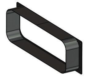
Table of contents

Table of contents
                       1    PREFACE............................................................................. 4
                       2    Warnings.............................................................................. 5
                       3    TECHNICAL DATA............................................................... 8
                       4    PRODUCT PERSPECTIVES................................................ 9
                       5    PRODUCT OVERVIEW...................................................... 10
                       6    Control Panel..................................................................... 11
                            6.1 Symbols...................................................................... 12
                            6.2 Segment Screens....................................................... 13
                            6.3 Stove Hood Usage Type............................................. 13
                       7    Active carbon filter replacement..................................... 15
                       8    CLEANING AND PREVENTIVE MAINTENANCE............. 17
                            8.1 Cleaning of the metal oil filter and water tank............. 17
                       9    Induction Cooking System Working Principles............. 20
                            9.1 Cookware.................................................................... 20
                       10   Packing.............................................................................. 24
                       11   Installation and Assembly ............................................... 25
                       12   Assembly .......................................................................... 28
                       13   Connection Scheme ........................................................ 33
                       14   USE OF PRODUCT............................................................           34
                            14.1 Hood Panel ..............................................................       34
                            14.1.1 Automatic ventilation .............................................           35
                            14.1.2 Timer......................................................................   35
                            14.1.3 Metal Oil filter.........................................................     37
                            14.1.4 Active Carbon filter ...............................................          37
                            14.1.5 Starting the countdown of the active carbon filter..                          37
                            14.1.6 Stopping the countdown of the active carbon filter                            37
                            14.1.7 Metal oil filter and active carbon filter....................                 38
                            14.2 Stove panel...............................................................      38
                            14.2.1 3 level temperature mode......................................                39
                            14.2.2 Child lock ..............................................................     39
                            14.2.3 Power boost cooking mode selection ...................                        40
                            14.2.4 Bridge selection ....................................................         40
                            14.2.5 Timer .....................................................................   41
                       15   Power Levels..................................................................... 43
                       16   Process plate..................................................................... 44
                       17   Accessories and Spare Parts.......................................... 45
                            17.1 Accessory................................................................. 45
                       18   AUTHORIZED SERVICE.................................................... 50

11.02.2021          FLOW-IN PRO USER MANUAL EN                                                                    3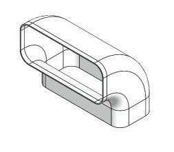
PREFACE

1      PREFACE
                    Follow the step-by-step instructions in this manual.
                    The manufacturer accepts no responsibility for any negativity,
                    damage or fire that may occur in the appliance as a result of not
                    following the instructions given in this manual. The appliance is
                    intended for domestic use only for cooking food and aspiration of
                    fumes from said cooking. Use for other purposes is not permitted
                    (eg. Heating the environment). The manufacturer accepts no
                    responsibility for improper use or incorrect setting of commands.

                               The appearance of the product may differ from
                               those depicted in the images in this booklet,
                               but the instructions for use, maintenance and
                               installation remain the same.

                    It is important to keep this user manual for future reference at any
                    time. Make sure that this user manual is not separated from the
                    product during the sale, lending or transfer of the product.
                    n Read the instructions carefully: It contains very important infor-
                      mation regarding installation, usage and safety.
                    n Do not perform electrical repairs on the product.
                    n Check whether all the components are usable before installing
                      the appliance. Otherwise contact the manufacturer and do not
                      continue installing.
                    n Make sure of the product’s integrity before installing. Otherwise
                      contact the manufacturer and do not continue installing.

4                FLOW-IN PRO USER MANUAL EN                                   11.02.2021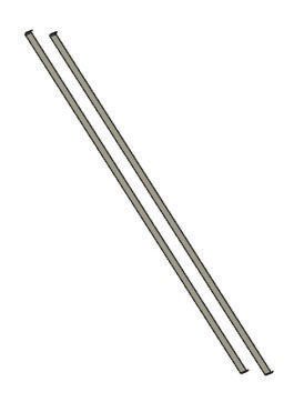
Warnings

2      Warnings
                                CAUTION!
                                Strictly follow the instructions specified on this
                                manual.

                     Before starting any installation procedure, the appliance must be
                     disconnected from the mains.
                     The installation or maintenance of the appliance must be carried
                     out by a qualified technician in accordance with the manufacturer's
                     instructions and in compliance with the local regulations in force on
                     safety.
                     In case of damage due to incorrect connection, the appliance will
                     be out of warranty.
                     Do not repair or replace any part of the appliance, unless it is spe-
                     cifically stated in the user manual.

                                CAUTION!
                                The appliance is not suitable for use in sockets
                                without grounding.

                     The power cable must be long enough to allow the appliance to be
                     connected to the mains.
                     In order for the installation to comply with the current safety regula-
                     tions, a standard-compliant switch is required, which ensures com-
                     plete disconnection of the network under overvoltage category con-
                     ditions.
                     Do not use multiple sockets or extensions.
                     After completing the installation, the user should no longer be able
                     to access the electrical components.
                     The areas touched during use are hot. Keep children away from
                     the appliance and under supervision.
                     The appliance can be used by children under 8 years of age, per-
                     sons with limited physical, mental and emotional abilities, and per-
                     sons with incomplete experience or knowledge only if they are
                     under the supervision of a responsible person or have been
                     informed about the safe use of the appliance and the dangers that
                     may occur.
                     Cleaning and maintenance should not be done by children without
                     supervision.
                     Before using the induction stove, people with pacemakers and
                     active implants should check whether their appliance is compatible
                     with the appliance. It is not possible to guarantee that 100% of the
                     appliances on the market will fulfil the electromagnetic compatibility
                     criteria in force and will not cause interference that will jeopardize
                     the correct operation of the appliance. It is also possible that
                     people wearing other appliances such as hearing aids may experi-
                     ence some discomfort.

11.02.2021        FLOW-IN PRO USER MANUAL EN                                                 5
Warnings

                  Do not touch the heater parts of the appliance during and after use.
                  Avoid contact with cloth or other flammable materials before all
                  components of the stove are sufficiently cooled.
                  Overheated greases and oils can easily catch fire. When cooking
                  food rich in oil, keep it under supervision.
                  Do not place metal items such as knives, forks, spoons and lids on
                  the stove as there is a possibility of overheating.
                  Do not use a steam cleaner.
                  Surface damage, discolouration and stains due to unsuitable deter-
                  gent. Use only detergent suitable for this type of stove.
                  Discolouration due to surface damage and pot friction. Lift and
                  carry pots and pans, do not push.
                  If the surface is cracked, turn off the appliance to avoid possible
                  electric shock.
                  The appliance is not suitable for operation via an external timer or
                  a separate remote control system.
                  Unsupervised cooking on an oil stove can be dangerous and cause
                  a fire.
                  The cooking process should always be monitored.
                  NEVER try to extinguish the fire with water. On the contrary, turn
                  off the stove immediately and smother the flames using a fireproof
                  lid or a cover.
                  Do not put any objects on the stove.
                  Before connecting the appliance to the electricity network, check
                  the information plate at the bottom of the stove to make sure that
                  the electrical voltage and power values are compatible with the
                  network and the connection cable is suitable. In case of doubt,
                  contact a qualified electrical expert.
                  Important:
                  After use, turn off the stove using the control and do not rely on the
                  pan sensor.
                  To prevent liquids from overflowing, reduce heat input when boiling
                  or heating liquids.

                             When your appliance is in operation and there is a
                             water overflow or a wet cloth is placed, your appli-
                             ance shuts down to protect itself. To restart your
                             appliance, you must unplug the power cord and
                             plug it in again.

                  Do not leave an empty pot or pan on the heater components or
                  without a container.
                  After completing the cooking process, turn off the relevant section.

6              FLOW-IN PRO USER MANUAL EN                                    11.02.2021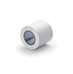
Warnings

                Using a high power function such as a booster is not suitable for
                heating some liquids such as cooking oil. High temperature can be
                dangerous. In these cases, it is recommended to use a lower
                heating power.
                The containers should be placed directly on the stove and cen-
                tered. There should be no other objects between the pot and the
                stove.
                When there is high heat, the appliance automatically reduces the
                power level of the cooking areas.
                Before any cleaning or maintenance, disconnect the product from
                the mains by unplugging or by turning off the cabinet's main switch.
                Wear work gloves for all installation and maintenance operations.
                The inside and outside of the appliance should be cleaned fre-
                quently (AT LEAST ONCE A MONTH). Also, follow what is clearly
                stated in the maintenance instructions.
                Failure to comply with standards regarding the cleaning of the
                appliance and the cleaning and replacement of the filters creates
                the risk of fire.
                Frying should be done under control to prevent the overheated oil
                from catching fire.

                           When the stove is in operation, accessible parts of
                           the hood become hot.

                           CAUTION!
                           Do not connect the appliance to the power grid
                           until the installation is completely complete.

                In terms of safety measures and technical measures to be adopted
                for smoke evacuation, strictly comply with the stated facts in the
                regulations of the local competent authorities.

11.02.2021   FLOW-IN PRO USER MANUAL EN                                             7
TECHNICAL DATA
3 TECHNICAL DATA
Flow-in Pro Product Features
Supply voltage 220-240 V(~) 50/60 Hz - 380-415 V(~) 2N(~) 50/60
Hz
Frequency 50/60 Hz
Max. power consumption 7360 W
Fuse protection / power source 2x16 A /1x32 A
Product dimensions (width/depth/height) 780x520x210
STOVE
Power levels 1-9 P
Front cooking area cooking pot size 190mm
Front cooking area power value 2000 W / 2800 W
Rear cooking area cooking pot size 190mm
Rear cooking area power value 1500 W / 2000 W
Stove power efficiency_EN 60350-2
1st cooking area power consumption 172.25 (Wh/kg)
2nd cooking area power consumption 175.79 (Wh/kg)
3rd cooking area power consumption 174.01 (Wh/kg)
4th cooking area power consumption 173.61 (Wh/kg)
Power efficiency value 173.92 (Wh/kg)
Oil filter
Oil capacity 60 hours
Oil filter service life 2 years
8 FLOW-IN PRO USER MANUAL EN 11.02.2021PRODUCT PERSPECTIVES
4 PRODUCT PERSPECTIVES
R
5 482
140,5
126
195
319
520
780
740
58
210
60
152
145
512
520
480
453
210
363 20
Fig. 1: Flow-in Pro üstten / önden / yandan görünümü
11.02.2021 FLOW-IN PRO USER MANUAL EN 9PRODUCT OVERVIEW
5 PRODUCT OVERVIEW
1
2
3
4
5
6
8 7
9
10
Fig. 2
1- Decorative Lid 6- Control Panel
2- Oil Filter 7- Water Tank
3- Carbon Filter Cover 8- Elbow (Optional)
4- Carbon Filter (Optional) 9- Fladkanal
5- Oil filter Bed 10- Flexi pipe
10 FLOW-IN PRO USER MANUAL EN 11.02.2021Control Panel
6 Control Panel
In the Worktop platforms, the stove and hood operating panel con-
sists of electronic sensor keys (finger contact part) and display
panels.
2
3
Fig. 3: Control panel located on the product
1 - Stove Hood Panel
2 - Timer Panel
3 - Stove Panel
11
6 7 8 9 10
12 13 14
Fig. 4: Control panel detail
Do not place wet towel or extremely hot pot on the
Worktop control panel.
11.02.2021 FLOW-IN PRO USER MANUAL EN 11Control Panel
Symbols
6.1 Symbols
Order Symbol Explanation
Hood
1 Automatic ventilation button
2 Activation of hood field button
3 Hood level detector button
4 Power-assisted ventilation button
5 Timer button
Stove
6 3 level temperature button
7 Enabling stove zone - reset button
8 Stove cooking level indicator
button
9 Power-assisted cooking button
10 Bridge button
11 Timer button
12 Pause/Resume selection button
13 Power On/Off button
14 Child Lock button
12 FLOW-IN PRO USER MANUAL EN 11.02.2021Control Panel
Stove Hood Usage Type
6.2 Segment Screens
Product Indicator Explanation
Power levels
Max. power (Booster)
Product is not active
Automatic mode
There is no pot on the stove or the pot is not suit-
able.
3 level temperature mode activation indicator
Standby mode
Pause mode
Metal oil filter warning
Active carbon filter warning
Time display
Error display
6.3 Stove Hood Usage Type
Depending on the model you purchased, the stove hood is in
exhaust air mode or recirculating air mode.
Exhaust Air Mode
The absorbed air is cleaned by the grease filters, and is discharged
through a piping system.
NOTICE!
Exhaust air or an active smoke must be transferred
to a waste gas flue; or a flue used for ventilation of
the places, where heat sources are installed.
11.02.2021 FLOW-IN PRO USER MANUAL EN 13Control Panel
Stove Hood Usage Type
n If exhaust air or an active smoke is to be transferred to a waste
gas flue; you need to obtain permission from an authorized
chimney sweep or an authorized engineer.
Circulating Air
Absorbed air is cleaned by the grease filters and an active
carbon filter, and then it is transferred back to the kitchen.
You need to install an active carbon filter, in order to catch the
substances, which cause stink in the circulating air. Consult
your authorized dealer to know the different opportunities avail-
able for enabling the appliance to function in circulating air
mode. You can buy the accessories required for this process
from the relevant outlets, authorized technical service or online
sales center.
Provide adequate ventilation to remove moisture.
14 FLOW-IN PRO USER MANUAL EN 11.02.2021Active carbon filter replacement
7 Active carbon filter replacement
1. First remove the water tank to replace active carbon filter
(Fig. 5).
1
Fig. 5
1 - Water Tank
2. Remove the active carbon filter lid (Fig. 6).
WARNING!
Do not put the active carbon filter in the dish
washer.
Wash it with a soft cloth in warm soapy
water.
Fig. 6
11.02.2021 FLOW-IN PRO USER MANUAL EN 15Active carbon filter replacement
3. Pull the active carbon filter to the right first, then remove it by
twisting it towards yourself (Fig. 7).
Replace the carbon filter you have taken out with a new one.
Attaching the Active Carbon Filter
Attach the active carbon filter by performing the reverse of
the procedures given above.
1
Fig. 7
1 - Active Carbon Filter
16 FLOW-IN PRO USER MANUAL EN 11.02.2021CLEANING AND PREVENTIVE MAINTENANCE
Cleaning of the metal oil filter and water tank
8 CLEANING AND PREVENTIVE MAINTENANCE
CAUTION!
Cleaning and user maintenance of the appliance
shall not be performed by unattended children.
n The surface could be damaged due to aggressive and abrasive
cleaning agents. Never use aggressive and abrasive cleaning
agents. Supply your cleaning and protective substances that
are appropriate for your appliance from the authorized tech-
nical service.
n Clean the surfaces with a soft and damp cloth, dish-washing
liquid or mild glass cleaning agent. Soften the dry, sticky dirt
with a damp cloth. Do not scrape!
n It is not appropriate to use dry cloths, sponges that may
scratch, materials that require rubbing, and other aggressive
cleaning agents containing sand, soda, acid or chlorine.
n Clean the stainless steel surfaces in their brushing direction
only.
n Cleaning metal oil filters Used metal oil filters catch the grease
particles from the moist and steam in the kitchen. Clean the
metal grease filters about every three months, under normal
use conditions (1-2 hours a day).
n Do not use excessively effective, acidic or alkaline cleaning
agents.
n You can clean the metal grease filters in the dishwasher or by
hand.
n Do not apply spray cleaning supplies directly to the product.
n Do not keep flammable and/or heavy decorative items on the
product.
8.1 Cleaning of the metal oil filter and water tank
WARNING!
Risk of fire due to oil sediments in metal oil
filter!
There is a risk of fire due to oil sediments in metal
oil filter.
– Clean the metal oil filter at least every 2 weeks
when the oil filter cleaning warning is dis-
played.
– Never operate the appliance without a metal oil
filter.
11.02.2021 FLOW-IN PRO USER MANUAL EN 17CLEANING AND PREVENTIVE MAINTENANCE
Cleaning of the metal oil filter and water tank
NOTICE!
Material damage may occur due to falling of the
metal oil filter.
Removing the metal oil filters
1. n To remove the metal oil filter, first remove the decorative
lid and then the metal oil filter in the direction of the arrow
().
1
2
c
Fig. 8
1 - Decorative lid
2 - Metal Oil Filter
Manual cleaning 2.
NOTICE!
Material damage due to wrong detergent!
Soften the metal oil filter in hot water and clean it with a soft
brush.
3. Rinse the metal oil filter in hot water.
Washing in a dishwasher 4. Place the metal oil filter in the dishwasher loosely and steeply
and without any other dishes.
5. Start a program with a maximum temperature of 55° C.
Colour changes may occur due to cleaning in
the dishwasher. These do not adversely
affect the function of the metal oil filter.
After cleaning 6. Allow the metal oil filter to dry on an absorbent coaster.
7. Placing the metal oil filters
Attach the metal oil filter by performing the reverse of the pro-
cedures given above.
Cleaning the Water Tank
18 FLOW-IN PRO USER MANUAL EN 11.02.2021CLEANING AND PREVENTIVE MAINTENANCE
Cleaning of the metal oil filter and water tank
A water container is inserted in the appliance to hold the water that
go inside the appliance during cooking or cleaning. Water tank
capacity is 1.7 litres.
Clean the water tank once a week.
WARNING!
Do not put the water tank on the dishwasher.
– Wash it with a soft cloth in warm soapy water.
11.02.2021 FLOW-IN PRO USER MANUAL EN 19Induction Cooking System Working Principles
Cookware
9 Induction Cooking System Working Principles
Induction cooking system is based on electromagnetic induction
physics discipline. The main feature of such a system is that the
energy is transferred directly from the induction coil to the pot. An
induction coil is placed under each induction cooking area. If the
cooking area is turned on, this coil creates a magnetic field that
acts directly on the bottom of the pot and heats it. The cooking
area is heated only indirectly by the heat emitted by the pot. Induc-
tion cooking areas only work if the cookware has a magnetizable
base. Induction automatically takes into account the size of the pot
used, which means that only the area in the cooking space occu-
pied by the bottom of the pot is heated. Pay attention to the min-
imum pot base diameter.
Compared to electric stoves, your induction stove has a number of
advantages.
n Safer: Minor heat on the glass surface.
n Faster: Duration when heating a meal is shorter.
n More precise: Stove commands are more active.
n More effective: 90% of the energy consumed is turned into
heat. As soon as the pot is removed from the stove, it inter-
rupts the heat transfer so that there is no unnecessary heat
dissipation.
9.1 Cookware
Only use pots with the Induction Suitable ( ) symbol.
Important:
To avoid permanent damage to the stove surface, do not use the
following types of pots:
n Pots with a not completely flat bottom.
n Metal pots with enamel base.
n Pots with a rough bottom to prevent scratching the surface.
Never place hot pots or pans on the surface of the
control panel of the stove.
Containers Used
Magnetic power is used to generate heat in induction stove. There-
fore, the containers must contain iron. With a simple magnet you
can check if the pot is made of magnetic material. Pots are not
suitable unless they are magnetically detectable.
20 FLOW-IN PRO USER MANUAL EN 11.02.2021Induction Cooking System Working Principles
Cookware
Recommended pot bottom diameters
Fig. 9
CAUTION!
If the pots are not of the correct size, the cooking
areas will not burn.
Always lift your pots from your stove, never slide
them; this causes the glass to be scratched.
Make sure that the middle point of your pot is towards the center of
the pot on the product.
11.02.2021 FLOW-IN PRO USER MANUAL EN 21Induction Cooking System Working Principles
Cookware
2 3
1 4
1 2
2 3 4 3
1,5 - 2,0 kW 1,5 - 2,0 kW
190 mm 190 mm
1,5 - 1,8 kW
3,0 - 3,6 k W
1 4
2,0 - 2,8 kW 2,0 - 2,8 kW
1,5 - 1,8 kW
190 mm 190 mm
190 - 385 mm
Fig. 10
Use the pot to be used in each section in accordance with the
diameter of the pot.
22 FLOW-IN PRO USER MANUAL EN 11.02.2021Induction Cooking System Working Principles
Cookware
NOTICE!
The following sounds may occur depending on the
material of the cookware and the bottom of the
cookware used in the induction stove areas.
– Humming may occur when using a high power
level.
When the power level is lowered, the sound
decreases or disappears.
– Sounds such as crackling and whistling may
occur.
– If the stove is used heavily, the cooling fan can
run automatically. The cooling fan continues to
run for a while after the stove has been turned
off.
11.02.2021 FLOW-IN PRO USER MANUAL EN 23Packing
10 Packing
Packing
6
1 2 3 4 5
7 8 9 10 11 12
Fig. 11
1- Product 7- Flexi pipe
2- Metal Oil Filter 8- Sealant Tape
3- Decorative Lid 9- Sealant and heat isolating material
4- Water Tank 10 - Active Carbon Filter Lid
5- Rectangular Tube 11 Active Carbon Filter (Optional)
6- Short Elbow Short 12 User Manual
24 FLOW-IN PRO USER MANUAL EN 11.02.2021Installation and Assembly
11 Installation and Assembly
n Parts inside the appliance may have sharp edges. Use protec-
tive equipment.
CAUTION!
– The furniture that the appliance will be
mounted on should be resistant to 90°C tem-
perature.
– The durability of the furniture that will be
mounted on should also be ensured after the
cutting operations have been completed.
– Particularly in thin plates the carrying capacity
Fig. 12
and durability should be provided with suitable
support parts. Consider the weight of the appli-
ance by including additional loads. The rein-
forcing material used should be heat and mois-
ture resistant. The weight of the appliance is
specified in the label on the package.
– Clean the sawdust after cutting. Cover the cut
surfaces so that they are heat resistant and
waterproof.
– The cross-sectional surface angle to the
working plate should be 90°.
Counter Cutting Dimensions for Installation and Using Sili-
cone
Consider the specified safety distances for bench dimensions
(Fig. 13).
n The distance between the appliance and the back and front of
the cabinet should be 50 mm minimum.
n A minimum distance of 300 mm must be left from the right and
left sides of the appliance.
n Bench depth should be 600 mm minimum.
* It is also suitable for use of 100 mm depending on the ventilation
ducts to be used.
100*
Fig. 13
11.02.2021 FLOW-IN PRO USER MANUAL EN 25Installation and Assembly
Please consider the dimensions on Fig. 14 in minimum machine
600
dimensions.
800
140
Fig. 14
x ≥50 Set your counter in accordance with the counter section in Fig. 15.
Fig. 15
In built-in installation; Consider the bench cuts in Fig. 16.
784+-2
750 +
-2
R
5
524+- 2
490+- 2
600
0,7
0
17
6
10 - 40
Fig. 16
26 FLOW-IN PRO USER MANUAL EN 11.02.2021Installation and Assembly
In counter top installation; Consider the bench cuts in Fig. 17.
750 +- 2
490+- 2
600
15
10 – 40
Fig. 17
11.02.2021 FLOW-IN PRO USER MANUAL EN 27Assembly
12 Assembly
Consider the installation dimensions to prepare your counter
before starting the assembly (Fig. 18).
* 450 mm space is required to remove the water tank.
Fig. 18
A
25
7 5
12
52
99
B
0
30
Fig. 19
28 FLOW-IN PRO USER MANUAL EN 11.02.2021Assembly
Prepare your counter in accordance with the cutting dimensions
A (Fig. 19 / Fig. 20).
125
52
257
CAUTION!
Check your counter dimensions before starting
B installation.
After preparing your counter top in accordance with the speci-
fied dimensions, proceed to the installation steps below.
99
300
Fig. 20
1 - Decorative lid
1 2 - Oil Filter
3 - Water tank
Take out the decorative lid, oil filter and water tank from the product
2 during installation to prevent them from falling and being damaged
(Fig. 21).
3
Fig. 21
11.02.2021 FLOW-IN PRO USER MANUAL EN 29Assembly
Before placing your product on the counter, place the product
upside down on the counter in order to adhere the sealing and heat
insulating materials (Fig. 22).
When placing the worktop product on the counter,
be careful not to damage it.
Fig. 22
Separate the heat insulating material from the tape and attach it to
your product (Fig. 23).
Fig. 23
1 - Elbow pipe (short)
1
Install the elbow pipe as in the arrow mark (Fig. 24).
Fig. 24
30 FLOW-IN PRO USER MANUAL EN 11.02.2021Assembly
1 - Sealant tape
To prevent air outflow from the junction point of the product and the
elbow pipe, stick the joint part with sealing tape (Fig. 25).
1
Fig. 25
1 - Product
2 - Counter
n To place the product inside the counter, lift it from the counter
and bring it to a flat position.
1
n Place the back of the product on the counter first ( Fig. 26/A).
A B Then place the front of the product (Fig. 26/B).
2
Fig. 26
1 - Elbow pipe
2 - Rectangular pipe
Install the rectangular pipe on the elbow pipe as in the arrow mark
1 (Fig. 27).
2 Tape the junction point of the two pipes with
sealant tape.
Fig. 27
11.02.2021 FLOW-IN PRO USER MANUAL EN 31Assembly
1 - Rectangular pipe
2 - Flexi pipe
After passing the Flexi pipe through your counter, attach it to the
rectangular pipe as in the arrow (Fig. 28).
Tape the junction point of the two pipes with
1 sealant tape.
2
Complete the remaining part of your assembly with
the materials you will get from the accessories and
spare parts section, and discharge the air outlet
Fig. 28 outside your home.
Use of silicone after assembly;
1
2
Fig. 29: Built-in installation
1 - Heat resistant black silicone
2 - Sponge
11
After completing the installation of your appliance, fill the remaining
2 spaces on your counter with heat resistant silicone ( Fig. 29/
Fig. 30).
Fig. 30: Counter top installation
After filling the remaining spaces with heat
resistant silicone, wipe the surface of your stove
and counter with a damp cloth to prevent stains.
1 - Protective Foil
When you complete your installation, remove the protective foil on
the worktop product (Fig. 31).
1
Fig. 31
32 FLOW-IN PRO USER MANUAL EN 11.02.2021Connection Scheme
13 Connection Scheme
PE
N
BLUE
GREY
1 2 3
220-240V ~ 50/60Hz
5 4
BLACK
BROWN
L
PE 220-240V
PE
GREY
BLUE
N1 N2
380-415V ~ 2N~ 50/60Hz
1 2 3
5 4
L1 L2
BROWN
BLACK
220-240V
PE 220-240V
Fig. 32
11.02.2021 FLOW-IN PRO USER MANUAL EN 33USE OF PRODUCT
Hood Panel
14 USE OF PRODUCT
14.1 Hood Panel
Fig. 33
Symbol Explanation Function
Automatic ventilation It automatically adjusts the ventila-
tion level according to the active
cooking areas and removes the
steam and odors that occur.
The cooking areas work as long
as they are active.
Activation of hood field It is used to activate / deactivate
the manual ventilation feature and
to exit the active program you
have selected.
Hood level detector To change the ventilation level;
You can increase or decrease the
ventilation level by sliding your
finger left or right.
Power-assisted ventilation It is used to operate your hood at
the maximum level. It is used
actively for maximum 9 minutes.
Timer It is used to activate the timer fea-
ture. The timer can be set from
the stove control area.
To activate your appliance, press the on / off ( ) button for 3 sec-
onds. When your appliance is turned on, it gives an audible
warning and the aspirator screen goes to standby mode as in
Fig. 34 Fig. 34.
To start ventilation level 0, press the activation button on the hood
control panel (Fig. 35).
It returns to standby mode after 30 seconds of inactivity (Fig. 34).
Fig. 35
To determine the ventilation level, slide the level indicator button
( ) on the hood control panel to the right /
left with your finger (Fig. 36).
Fig. 36
To activate the power-assisted ventilation feature, press the power-
assisted ventilation button ( ) on the hood control panel (Fig. 37).
Fig. 37 After 9 minutes, the ventilation level automatically becomes 9.
34 FLOW-IN PRO USER MANUAL EN 11.02.2021USE OF PRODUCT
Hood Panel > Timer
Power-assisted ventilation feature is valid for 9
minutes.
If you want to activate the standby mode without waiting for 30 sec-
onds, press the hood activation button ( ) on the hood control
area for 2 seconds (Fig. 38).
Fig. 38
14.1.1 Automatic ventilation
To switch your appliance to automatic ventilation mode, first press
the hood activation area, then the automatic ventilation button
( ).
Fig. 39
Your appliance automatically adjusts the ventilation level according
to the active cooking areas and cooking levels.
If you switch your appliance to automatic mode, the hood ventila-
tion works as long as the cooking areas are working.
When all active cooking areas are closed, the hood ventilation level
is gradually lowered to stand-by within 5 minutes to remove
residual steam and odours. During this process, the timer symbol
lights up actively. (Fig. 40).
When the automatic mode and cooking areas are active on your
appliance, press the automatic ventilation ( ) button to exit the
automatic mode.
Fig. 40
If you want to adjust your hood in automatic mode (if you want to
increase or decrease the ventilation level), you can make changes
with the aspirator level determiner button
( ). The ventilation level you man-
ually changed is valid for 5 minutes. It switches back to automatic
mode after 5 minutes (Fig. 41).
When you manually intervene in the automatic mode, the auto-
matic mode ( ) symbol on the screen and the level you have set
flashes alternately for 5 seconds. The timer symbol also flashes
within these 5 seconds.
Fig. 41 At the end of 5 seconds, the ventilation level and timer symbol you
selected on the screen remain fixed.
Automatic ventilation only works when cooking
areas are active.
14.1.2 Timer
The hood timer is limited to 95 minutes. The timer can be set in
increments of 5 minute.
11.02.2021 FLOW-IN PRO USER MANUAL EN 35USE OF PRODUCT
Hood Panel > Timer
Long pressing the plus and minus keys increases
the timer by 10 minutes and increments.
Press the timer button ( ) on the hood control panel to activate
the timer feature. Determine the time you want to enter with the
plus / minus ( / ) keys on the stove control panel (Fig. 42).
The timer is set to 5 minutes and its multiples
(10-15-20-25, etc.).
Fig. 42
After the set time flashes for 3 seconds on the screen, it stabilizes
and shows the remaining time (Fig. 43).
Fig. 43
When you set the timer for 10 minutes or more, the hood starts to
slow down the ventilation rate until the hood stops in the last 5
minutes of the countdown, after 5 minutes the hood turns off. The
dot on the screen flashes for 30 seconds, and then remains in
standby mode (Fig. 44).
Fig. 44
During this time, the timer can be canceled by holding down the
minus ( ) key on the stove control panel or rearranged with the
plus / minus ( / ) keys. After the timer is set to “00”, it will
flash 3 times and then the timer icon will disappear (Fig. 46).
Fig. 45
Fig. 46
36 FLOW-IN PRO USER MANUAL EN 11.02.2021USE OF PRODUCT
Hood Panel > Stopping the countdown of the active carbon filter
14.1.3 Metal Oil filter
When the metal oil filter duration is up (60 hours), the metal oil filter
symbol will flash once per second for a total of 5 seconds. The
metal oil filter symbol lights up in the background until it is disabled
after 5 seconds.
After cleaning/replacing your metal oil filter, timer press the
button for 3 seconds to reset the filter symbol and the metal oil filter
countdown timer (Fig. 47).
Fig. 47
14.1.4 Active Carbon filter
Your appliance will come with a passive carbon filter counter as
factory default. If you are to use the appliance with an active
carbon filter, you must activate the active carbon filter counter.
When the active carbon filter duration is up (150 hours), the active
carbon filter symbol will flash once per second for a total of 5 sec-
onds. The active carbon filter symbol lights up in the background
until it is disabled after 5 seconds.
After cleaning/replacing your active carbon filter, press the
button for 3 seconds to reset the filter symbol and the carbon filter
countdown timer.
Fig. 48
14.1.5 Starting the countdown of the active carbon filter
When your appliance is turned on and when you hold down the
automatic ventilation button ( ) and the timer button ( ) for
about 5 seconds, you will hear an audible warning sound from your
Fig. 49 appliance and then the active carbon filter icon ( ) symbol will
light continuously for 20 seconds. This status indicates that the
active carbon filter counter is active and starts counting down.
14.1.6 Stopping the countdown of the active carbon filter
When your appliance is turned on and when you hold down the
automatic ventilation button ( ) and the timer button ( ) for
about 5 seconds, you will hear an audible warning sound from your
Fig. 50 appliance and then the active carbon filter icon ( ) symbol will
light continuously for 5 seconds. This indicates that the active
carbon filter counter is passive and does not countdown.
11.02.2021 FLOW-IN PRO USER MANUAL EN 37USE OF PRODUCT
Stove panel
14.1.7 Metal oil filter and active carbon filter
If the countdown of the metal oil filter and the active carbon filter
ends at the same time or successively and their symbols are dis-
played on the panel as a notification, the priority for deactivation is
the metal oil filter and then the active carbon filter (Fig. 51) See
also (13.1.5 /13.1.6.
Fig. 51
14.2 Stove panel
Fig. 52
Symbol Explanation Function
3 level temperature mode button It is used for keeping foods at dif-
ferent temperatures, keeping them
warm and heating them.
Button to enable-disable the stove It is used to activate the cooking
area area and to deactivate the
selected cooking level.
Stove level detection button It is used to determine the cooking
level.
Power boost cooking mode selec- It use used to operate the cooking
tion button areas in maximum level.
Bridge button The Bridge button is used to
operate the cooking areas in con-
nection.
Pause/Resume button It is used to suspend or reactivate
all active functions on the stove by
bringing the cooking power to
zero.
ON/OFF button It is used to open and close the
stove and hood control area.
Child Lock button It is used to prevent changes in
the stove and hood area while the
product is in operation.
Timer decrease button It is used to reduce the timer dura-
tion.
Timer increase button It is used to increase the timer
duration.
38 FLOW-IN PRO USER MANUAL EN 11.02.2021USE OF PRODUCT
Stove panel > Child lock
To activate your appliance, open it by pressing the on / off ( )
button for 3 seconds. When your appliance is turned on, it beeps
once and goes into standby mode (Fig. 53).
Fig. 53
If the cooking area and power level are not selected within 1
minute, the stove switches off automatically.
Before you start cooking, make sure that the
bottom of the pot and the cooking surface are
clean and dry.
Select the cooking area using the stove activation button, the zero
‘0’ flashes on the cooking compartment display. If the power level
is not selected within 5 seconds, the screen returns to standby
mode.
14.2.1 3 level temperature mode
If no suitable pan is placed on the stove, the dis-
play will automatically turn off after 1 minute.
Symbol Explanation Temperature (˚C)
Used for melting food and 50
defrosting frozen food.
It is used for warming up or 70
keeping food warm.
It is used for boiling, slow cooking 90
or keeping food near boiling tem-
perature.
14.2.2 Child lock
By pressing the child lock button ( ) for about 3 seconds, you will
lock the controls of your appliance. When you lock your appliance,
'Lo' will appear on your screen.
When the child lock is active on your appliance, all buttons except
the on/off button ( ) are passive.
When you turn off your appliance while the key
lock is active, you cannot activate your appliance
without disabling the child lock.
11.02.2021 FLOW-IN PRO USER MANUAL EN 39USE OF PRODUCT
Stove panel > Bridge selection
14.2.3 Power boost cooking mode selection
Press the button to activate the power-assisted cooking area
(Fig. 54).
Power-assisted cooking button is valid For max 5 minutes.
Fig. 54
Power boost cooking cannot be activated on all
stoves at the same time.
Front cooking areas have more power than rear
areas. Therefore, if you want to do power-assisted
cooking in one of the front cooking areas, you
cannot do any cooking on the cooking areas
behind the respective area.
14.2.4 Bridge selection
2 3 It is the ability to create a single section with the same power level
1 4
by working together with the cooking areas of 1 and 2 and the
cooking areas of 3 and 4.
1 2 3 4
1-2 3-4
Fig. 55
To activate the bridge function; you activate the bridge function by
pressing the bridge button ( ) located on the cooking areas (1 or 4
numbered areas). The bridge symbol appears on the cooking area
panels that you have created a bridge function for (Fig. 56).
You can check the cooking level on the cooking area with the
bridge button.
CAUTION!
Make sure that the pot is placed in the center of a
single cooking area. The most suitable container is
an oval or rectangular pot.
Fig. 56
Overheating protection
When excessive heat is detected in your appliance, your stove will
automatically turn off.
40 FLOW-IN PRO USER MANUAL EN 11.02.2021USE OF PRODUCT
Stove panel > Timer
Detecting Small Items
If an unsuitable or non-magnetic pan (such as aluminium) or some
other items (knife, fork, key) are left on the stove, the stove will
automatically switch to standby within 1 minute.
Automatic Shutdown Protection
n When the pot is removed, your stove will enter standby mode
after 1 minute, and after 2 minutes the stove will turn off.
n The operating times of your stove at various power levels are
listed in the table below.
Power 1-3 4-6 7-8 9
level
Default 360 180 120 90
operating
time (min.)
14.2.5 Timer
The stove cooking area timer is limited to 90 minutes. The timer
can be set in increments of 1 minute.
After the stove compartment you have selected to activate the
timer feature, determine the time you want to enter by using the
/ buttons on the control panel (Fig. 57).
The set time flashes 3 times on the display and the timer symbol
lights up on the active stove (Fig. 57).
Fig. 57
14.2.5.1 Using the timer as an alarm
After stopping flashing the digits of the stove level after the stove
compartment you have selected to activate the timer feature, deter-
mine the time you want to enter with the / buttons on the
control panel (Fig. 58).
Each time you touch the / buttons of the timer, the time
decreases or increases by 1 minute.
The set time flashes 3 times on the display and the timer symbol
lights up on the active stove (Fig. 58).
Fig. 58
When the timer expires, the appliance beeps for 30 seconds, then
the timer indicator turns off.
11.02.2021 FLOW-IN PRO USER MANUAL EN 41USE OF PRODUCT
Stove panel > Timer
14.2.5.2 Using the timer as alarm and power cut
To activate the timer feature, determine the time you want to enter
with the / buttons on the control panel, before the flashing of
the digits of the stove level after the stove area you have selected
stops (Fig. 59).
Each time you touch the / buttons of the timer, the time
decreases or increases by 1 minute.
The set time flashes 3 times on the display and the timer symbol
lights up on the active stove (Fig. 59).
Fig. 59
When the timer expires, the appliance beeps for 30 seconds, then
the relevant cooking area turns off.
When the timer alarm and power cut alarm are
used together, the display shows the remaining
alarm time with first priority.
42 FLOW-IN PRO USER MANUAL EN 11.02.2021Power Levels
15 Power Levels
Power level Process type Usage (indicates expe-
rience and cooking
habits)
Max. power Boost Quick heating For fast boiling, roasting,
to start cooking, for frying
food with ice
8-9 Frying - Boiling To boil, roast, start
cooking faster, to fry
frozen food
High power 7-8 Roasting - sautéing - For boiling, cooking,
boiling - grilling grilling and sautéing
(short duration, 7-12
minutes)
6-7 Frying - cooking - boiling Maintaining medium
- sautéing - grilling boiling, cooking and
grilling, sautéing,
(medium duration, 12-22
minutes), preheating
accessories
Medium power 4-5 Cooking - frying - sau- Boiling, maintaining mod-
téing - grilling erate boiling, cooking
(prolonged). Mixing
pasta with sauce
3-4 Cooking - boiling - thick- Mixing pasta with sauce
ening - mixing to cook foods (rice,
sauce, frying, fish) with
liquid (such as water,
wine, broth, milk) for a
long time
2-3 For cooking foods with
liquid (less than 1 litre:
water, wine, broth, milk)
for a long time (less than
1 litre: rice, sauces,
roast, fish)
Low power 1-2 Melting - defrosting - For softening butter,
keeping warm - mixing melting chocolate
slightly, defrosting small-
sized products, keeping
cooked foods warm,
keeping main dishes at
the same temperature
OFF (CLOSED) Zero power Stove stand-by or extin-
guishing
11.02.2021 FLOW-IN PRO USER MANUAL EN 43Process plate
16 Process plate
Food Class Meal or Power level and cooking stage
cooking type
First level Power Second level Power
Pasta - Rice Fresh pasta Heating water Booster-9 Cooking pasta 6-7
and continuing
boiling
Rice Frying 7-8 Cooking 3-4
Vegetable Boiling Boiling water Booster-9 Boiling 6-7
Fried Heating oil Booster-9 Frying 6-7
Sauted Heating acces- 7-8 Cooking 5-6
sories
Meat Poaching Heating pots 6-7 Cooking 4-5
Rosto Sealing 7-8 Cooking 4-5
Pan frying Frying with oil 7-8 Cooking 4-5
(oil starts
heating in 3rd
minute)
Chicken Thawing Heating acces- 1 Defrost 1
sories
Pan frying Cooking 7 Cooking 6-7
chicken and
continuing
boiling
Potatoes Frying potatoes Heating oil 9 Frying 9
Egg Frying Heating pan 6-7 Cooking 5-6
with butter or
oily food
Boiling Boiling water Booster-9 Boiling 6-7
Sauce Bechamel Boiling 6-7 Cooking 6-7
Sauce
Dessert-Cus- Pancakes Heating acces- 6 Baking 6
tard-Cake sories
Puding Heating milk 5-6 Continuing sim- 3-4
mering
Custard Heating milk 5-6 Cooking 5-6
Melting choco- Starting melting 1-2 Melting 1-2
late
Rice Puding Starting 6-7 Cooking 3-4
Cooking (Boiling)
44 FLOW-IN PRO USER MANUAL EN 11.02.2021Accessories and Spare Parts
Accessory
17 Accessories and Spare Parts
17.1 Accessory
WARNING!
Risk of injury due to wrong accessory or wrong
spare parts!
Due to the use of wrong or defective spare parts,
problems such as damages, malfunctions or com-
plete failure may occur in the appliance.
The use of incorrect spare parts or accessories
can cause injuries.
If unauthorized accessories or unauthorized spare
parts are used, the manufacturer's warranty is ter-
minated.
Purchase spare parts and accessories via contracted seller or cus-
tomer service.
11.02.2021 FLOW-IN PRO USER MANUAL EN 45Accessories and Spare Parts
Accessory
1 2 3 4
Fig. 60
YT207.1001.94 CIRCULATION KIT
Order Code Explanation Amount Size (mm)
1 YT207.1001.13 F-RBV 150 Pipe 1 227x174x94 -10
Bend Ver-
tical90°(4043078)
2 YT207.1001.14 F-VRO 500 150 flat 2 500x222x89
duct(4040075 )
3 YT207.1001.94 F-RBFLEX 1 1 550x227x94
system 150 pipe
bend(4043042)
4 YT207.1001.11 “ N-KLEB PVC duct 1 10.000X50
tape"
YM116.3410.601
222x89
46 FLOW-IN PRO USER MANUAL EN 11.02.2021Accessories and Spare Parts
Accessory
YT207.1001.92 (FRAME)
255x125
YM972.1000.52 (STOVE GLASS MOLD (INOX)
522x12
11.02.2021 FLOW-IN PRO USER MANUAL EN 47Accessories and Spare Parts
Accessory
YM115.7000.402 (STOVE GLASS DECOR MOLD BLACK)
522x12
YM131.7000.405 (VENT SHEET)
339x110
YT540.7000.0100.01 (CARBON FILTER)
48 FLOW-IN PRO USER MANUAL EN 11.02.2021Accessories and Spare Parts
Accessory
YT142.7000.01 (GREASE FILTER
İNOX)
YT142.7000.02 (GREASE FILTER
BLACK)
YT142.7000.03 (GREASE FILTER
ORANGE)
11.02.2021 FLOW-IN PRO USER MANUAL EN 49AUTHORIZED SERVICE
18 AUTHORIZED SERVICE
Possible Faults and What You Can
Do Before You Call Service:
A) If the appliance does not work in
any way:
n Check to see if the hood is plugged in or if the plug is fit prop-
erly into the socket.
n Check the fuse, to which the appliance is connected, as well as
the main fuse of your house.
If the performance of the appliance
is not enough and it creates high
noise when operating: n Are the metal filters clean? Check.
Troubleshooting
Fault description Cause Remedy
Product Does Not Work Check the power con- Mains voltage must be 220-240 V or 380-415 V, and
nection. product must be plugged into a grounded socket.
Illumination lamp does not Check the power con- Mains voltage must be 220-240 V or 380-415 V, and
operate nection. product must be plugged into a grounded socket.
Product's Air Intake is Check The Alumi- The aluminium cartridge filter should be washed once
Weak nium Filter. a month under normal conditions.
Product's Air Intake is Check the Air Outlet. Air Outlet Must Be Open.
Weak
Product's Air Intake is Check The Carbon In products that work with carbon filters, carbon filter
Weak Filter. must be replaced once in every 3 months under
normal conditions.
50 FLOW-IN PRO USER MANUAL EN 11.02.2021You can also read