FROM BIM REPRESENTATION TO FUNCTIONAL SIMULATION AND REAL TIME ADVANCED CONTROL
←
→
Page content transcription
If your browser does not render page correctly, please read the page content below
SpHERE
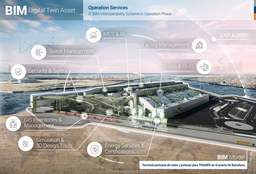
BIM DIGIT AL T WIN PL ATFORM
December 2021
FROM BIM
REPRESENTATION
TO FUNCTIONAL
SIMULATION AND
REAL TIME
ADVANCED
CONTROL
This project has received
funding from the European
Union’s Horizon 2020
research and innovation
programme under grant
agreement Nº 820805.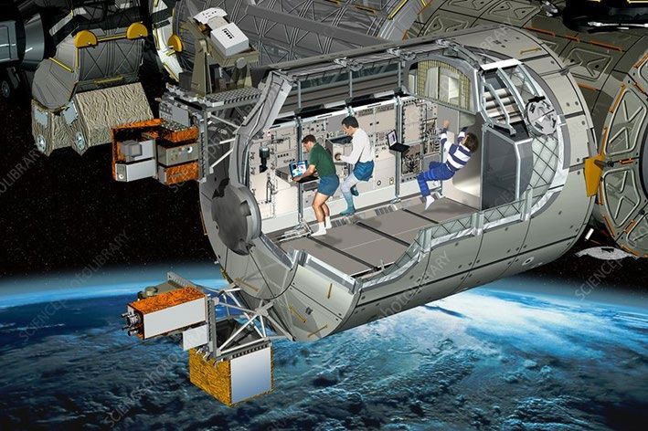
2 ||                                                                                                                                       || 3

December 2021

                                         AUTHORS
                                         •   Mr. E. Loscos, BDTA President
                                         •   Dr. R.H.E.M. Koppelaar, Ekodenge
                                         •   Mr. Angel Font, BDTA Senior Advisor
                                         •   Mr. Federico Seri, NUI Galway
                                         •   Dr. Rafael Sacks, Technion
                                         •   Ms. Rosa Mateos, Tecnalia
                                         •   Mr. Mathias Bonduel, NeanexTechnologies

                                                                                                       ABOUT SPHERE
                                         •   Mr. Wouter Borsboom, TNO
                                         •   Mr. Antonio Rivero, Empresarios Agrupados
                                             Internacional
                                         •   Dr. Enrique Blanco, CERN
                                         •   Mr. Mark Thomas, CEO Nextspace                           SPHERE is a 4-yearHorizon
DISCLAIMER                               •   Dr. Miguel Angel Sicilia, Universidad de Alcalá de
                                             Henares                                                  2020 project with 20 partners
 The opinion stated in this report
                                         •   Mr. JannePorkka, VTT                                     targeting the improvement
                                         •   Dr. Enrique Personal, Universidad de Sevilla
 reflects the opinion of the authors
                                         •   Mr. Servando Álvarez Domínguez, Universidad de           and optimization of
 and not the opinion of the European
 Commission. All intellectual property
                                             Sevilla                                                  building’s energy design,
                                         •   Ms. Regina Enrich, Eurecat
 rights are owned by SPHERE
 consortium members and are
                                         •   Mr. Guillermo Borragán, DLB chapter, VITO-Energy Ville   construction, performance,
 protected by the applicable laws.
                                         •   Mr. Pablo Vicente, BDTA PM
                                                                                                      and management, reducing
 Reproduction is not authorized
 without prior written agreement. The
                                                                                                      construction costs and their
 commercial use of any information                                                                    environmental impacts.
 contained in this document may
 require a license from the owner of
                                         CONTRIBUTORS
 that information.                                                                                    SPHERE seeks to develop a
                                         •   DMr. Esa Nykanen, VTT
                                         •   Mr. Peter Imbrechts, Neanex                              building centered Digital Twin
                                         •   Mr. EmreYontem, Ekodenge                                 Environment, involving not only
                                         •   Ms. Gisela Soley, Comet
                                         •   Mr. Sergio Velasquez, Comet                              the design and construction of
ACKNOWLEDGEMENT                          •   Dr. Carlos León, Universidad de Sevilla                  the building but also including
                                         •   Mr. Narciso Moreno, Universidad de Sevilla
                                         •   Mr. PekkaTuomaala, VTT                                   the manufacturing and the
 This project has received funding
 from the European Union’s Horizon
                                         •   Mr. KaleviPiira, VTT                                     operational phases.
                                         •   Mr. Pedro Cobas, Empresarios Agrupados
 2020 research and innovation                Internacional
 program under grant agreement Nº        •   Mr. Víctor Sánchez, Tecnalia                                     https://sphere-project.eu/
 820805.                                 •   Mr. José Sánchez Ramos, Universidad de Sevilla
                                         •   Mr. Mikel Borràs, IDP Ingenieria y Arquitectura
4 ||                                                                                                                                                                   || 5

                                                      KEYWORDS
       ABSTRACT                                       • Building Digital Twin
                                                      • Physical Twin
                                                                                             • Open BIM SPHERE
                                                                                             • Web Ontologies
                                                                                                                                      • Ontology Management
                                                                                                                                      • Human Thermal Model (HTM)
                                                      • BIM                                  • Linked Data and Web of                 • Human Ventilation Model (HVM)
                                                      • Real Estate                             Things                                • Microgrids
       Residential Building Digital Twin
                                                      • Facility Management                  • Mathematical Simulation                • DERs
       functional representation requires a
       new professional role (BDT Simulation          • Product Lifecycle                    • Software in the Loop (SIL)             • Trustworthy BDT
       Manager). This functional aspect of            • Management                           • Hardware in the Loop (HIL)             • Privacy
       the building digital twin covers all           • PLM                                  • SIMBOT                                 • Building Ethical Constraints
       phases of the building, from design and
                                                      • SCPS                                 • BMS
       concept to commissioning and real time
                                                      • Internet of Things (IoT)             • Virtual Commissioning
       management. It must be well coordinated
       with BIM and other services of the BDT.

       Mathematical simulation can reproduce
       functionalities of the different systems:
       passive building, ventilation networks,
       heating and cooling devices, meteorology
       and occupancy. Advanced Software in
       the Loop embedded in supervision and
       control devices can improve drastically
       the visibility of health, comfort and energy
       parameters. Performance contracts (as
       one economic implication) can make
       use of dynamic energy evaluations.
       Maintenance can be carried out effectively
       thanks to extra parameters derived from
       simulation, affecting not only equipment
       but networks and sensors.
       Challenges as Trustworthy BDTs and
       privacy and ethical constraints are
       considered, describing new aspects and
       solutions.

       The document point out next steps
       and possible lines of development,
       and the impact they can have in future
       EU policies. Especially microgrids and
       projection to smart cities is considered.          Figure 1: Conceptualisation of a Building Digital Twin Instance Interoperability Services (sketch by: M.Borràs)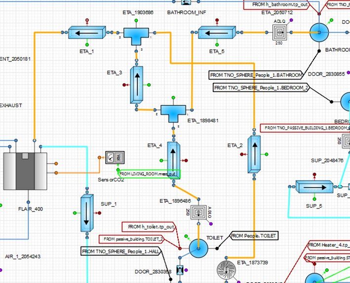
6 ||                                                                                                                                                                         || 7

                                                                                                3.1.- State of the Art in Other Sectors
                                                                                                   Gaia: The Living Earth

       TABLE OF CONTENTS                                                                           Bio Digital Twin
                                                                                                   Process Plant
                                                                                                   Aviation
                                                                                                   Automotive
                                                                                                3.2.- SIL vs HIL
                                                                                                3.3.- SRI Indicators
 ABOUT SPHERE 										                                                                  3        Concept and Methodology
 ABSTRACT 											                                                                     4        Assessment vs Monitoring, Analysis and Simulation in Real Time
 KEYWORDS 										                                                                      5     3.4.- Use Case TNO
 1. INTRODUCTION										                                                                8     3.5.- Location of Sensors
   1.1.- BDT, Definitions and Roles                                                             3.6.- Interaction of SIL and BMS
   1.2.- The 'Ontology Management' Problem of BDT´s                                             3.7.- Predictive Maintenance
       Some Problems with “Visual First” Approaches to Digital Twin Implementations                Information Retrieval: Sensors
 2. SIMULATION ACROSS BUILDING LIFE CYCLE 		                                              13       Data Storage: Edge or Cloud?
       Complexity and Size of the Models                                                           Data Access Rights
       Model for Design, for Commissioning and Model for Real Time Control                      3.8.- MPC
       Meteo and Occupancy in Real Time                                                            SIL Enabling Automated Assessment and Optimization.
       Less Sensors, More Intelligence                                                         4. PERFORMANCE CONTRACTS 						                                               77
       Simulation Deck Concept                                                                  4.1.- 'Stroomversnelling' Case
   2.1.- Energy Simulation and BDTs, Reducing the Gap                                           4.2.- The Meetscoalition.org
   2.2.- BDTs During Design and Construction
   2.3.- BIM models and SIM models, how to improve the linkage
                                                                                               5. TRUSTWORTHY BDTS                                                           81
                                                                                                5.1.- BDT and People
   2.4.- Monitoring the Real Building
                                                                                                5.2.- The Concept of a Trustworthy BDT Environment
   2.5.- Virtual Commissioning
                                                                                                5.2.1.- Background: Trustworthy AI
   2.6.- How a Digital Building Logbook Impacts the Digital Twin Uptake
                                                                                                   From Trustworthy AI to Trustworthy BDTE
   2.7.- Kubik Case
                                                                                                5.3.- Key Technical Components in Trustworthy BDTEs
   2.8.- Other Types and Strategies of Simulations
                                                                                                5.3.1.- Security in Data at the Edges
       Simulation of Ventilation
                                                                                                5.3.2.- Privacy-Preserving Computation
       The Challenge in Simulation of Ventilation in Residential Buildings
                                                                                                5.4.- Sphere and Trustworthy BDTE Design
       Ventilation and Covid-19 Pandemic
       Ventilation and Initiatives at BDTA                                                     6. NEXT STEPS                                                                 87
       Human Models                                                                             6.1.- Microgrids and Local Energy Communities
       The Human Factor in Thermal Control.                                                     6.2.- Human Models and Occupancy Interaction
       The Human Thermal Models of VTT                                                          6.3.- Energy Performance Contracts and Deep Renovation Wave
       The Human Factor in Ventilation Control                                                  6.4.- Digital Logbooks, Monitoring and Statistics
       The Human Ventilation Models of EAI                                                      6.5.- Less Sensors, More Intelligence
                                                                                                6.6.- Functional Simulation of All Building Phases, a New Project Concept?
 3. SOFTWARE IN THE LOOP CONCEPT                                                          53
                                                                                                6.7.- New Privacy Management Tools
       Control Problems and Help from SIL/HIL
       Differences with AI, Expert Systems, Machine Learning, Neural Networks, Big Data        REFERENCES                                                                    95
       Standards in This Field                                                                 ANALYTIC INDEX 			                                                            96
                                                                                               ACRONYMS                                                                      96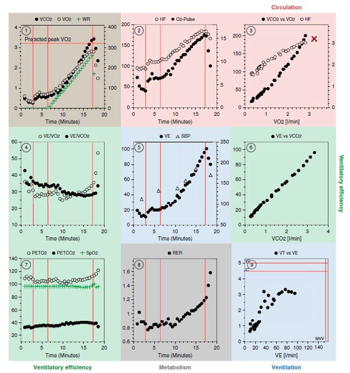
8 || Introduction                                                                                                                                                                                             Introduction || 9

1.-INTRODUCTION
                                                                                                                         Whereas BDTM and BDTCM are generic technical profiles the last one (BDTSM) has an
                                                                                                                         advanced engineering concept behind the fact that it must be taking decisions about matters that
                                                                                                                         today may seem too ahead in time. The Simulation Manager “should be responsible for the whole
                                                                                                                         aspects related to the development and maintenance of an evolving simulation model correlated to
                                                                                                                         the physical smart and connected asset system7.

Digital Twins are one of the most relevant trends presently found among digitalization across                            This means to map or link entities of designed or physical as built elements with simulation
all the sectors. From health1 to environment2, Digital Twinning appears as an unstoppable                                components in the mathematical engine used in each case.
wave although they are often targeting just one of the most relevant benefits attached to the                            This mathematical simulation should not work isolated and will have several interfaces: real time
Digital Twin Environments: the Predictive purpose3.                                                                      BMS, asset management, outside meteorological and ambient conditions,...

In the same way scale models has been used since humanity started to use tools - since they                                                        The Simulation Manager would
are actually just this -, their evolved Digital counterparts could offer the same benefits and
beyond. However, the force that the predictive purpose entails, is by itself more than enough                                                      ultimately be responsible for the
to justify the effort of developing Digital Twins of any connected physical object.
                                                                                                                                                   certification / validation that the
Following the relevance of the behavioral prediction for any stakeholder related to valuable
objects in any cycle of its lifespan, this White Paper focuses on the strategies to be                                                             model "responds to reality" to the
considered when the object itself belongs to the AECOO4 sector.
                                                                                                                                                   extent defined
About value, real estate assets could be products to sell, to rent or to be financed,
engineering objects to be developed, construction places to erect or retrofit, energy sources,                           “Based on the correlation among data coming from both Digital and Physical currents, DTSM
wells or storages, materials banks, Greenhouse gases emission points…, but after all this,                               shall then establish the validation and even certification methods (depending on the grade of
they are also our work or leisure places, and above all this, our homes.                                                 implementation of the Digital Twin) which will allow not only an iterative improvement of the
                                                                                                                         simulation, but opens a wide open window to the optimization of the control operation of any asset”.
1.1.- BDT, Definitions and Roles
                                                                                                                         Following this, these methods are crucial to reduce the gap between simulated and monitored
In the previous White paper published in 2019 , three new roles were defined as three
                                                               5
                                                                                                                         data during the commissioning of the Building Services. This validation between design and
necessary facets of a professional person or team to guarantee a proper setting,                                         operation simulations might hence underpin the future Predictive functions of any BDTI and has
development, duration, usage, and maintenance of Building Digital Twins across their                                     a relevant importance in the case of Performance Based Contracts. Since these performance
life scales. Beyond the expected future improvements in standards and automatisms for                                    based procurement is based on real measurements, including tolerances, current gap between
Data Collection and Integration (e.g. Data Reference Architecture Models6), a minimum                                    simulation models and measures have to be significantly reduced. The SimulationManager would
representative number of datasets have to be gathered to duly represent a building.                                      ultimately be responsible for the certification / validation that the model “responds to reality” to the
                                                                                                                         extent defined.
Following a functional approach at least we can speak of three new profiles, which respond
to the coordination of the whole DT (BDT Manager, or BDTM), the need of interaction during
                                                                                                                         1.2.- The ‘Ontology Management’ Problem8 of BDT´s
time (BDTConfiguration Manager, or BDTCM), and the need or representing the functionality                                What is a Digital Twin and why? Asset management 2.0? Many valid views exist of course but
of the building in a trustable way (BDTSimulation Manager, or BDTSM). These roles are                                    Mark Thomas, CEO of Nextspace, give us his own perspective.
broadly explained in the mentioned white paper. They are abstract roles and they could be
organized in different ways.                                                                                             Perhaps most traditionally, DT’s are associated with simulation and analytics applications such as
                                                                                                                         predictive maintenance, system I/O simulation, using IoT, AI, FEA, CFD etc. to replicate the inputs,
1 A Novel Cloud-Based Framework for the Elderly Healthcare Services Using Digital Twin. DOI10.1109/ACCESS.2019.2909828   behaviors and outputs of the real world or its devices in some way. My view is that a DT needs 3
2 https://www.sciencemag.org/news/2020/10/europe-building-digital-twin-earth-revolutionize-climate-forecasts             critical components to be “valuable”; i.e. able to stated, communicated and optimized (and so then
3 Grieves, M. & Vickers, J. Origins of the Digital Twin Concept. 23, August 8 pages (2016)
4 AECOO: Architecture, Engineering, Construction, Operation & Ownership
                                                                                                                         the real world) against chosen goals; e.g. financial, environmental, social.
5 SPHERE: Digital Twin Definitions for Buildings: https://sphere-project.eu/articles-papers/#
                                                                                                                         7 Page 42, " SPHERE: Digital Twin Definitions for Buildings" White Paper.
6 https://www.internationaldataspaces.org/wp-content/uploads/2019/03/IDS-Reference-Architecture-Model-3.0.pdf
                                                                                                                         8 Collaboration of Mark Thomas, CEO of Nextspace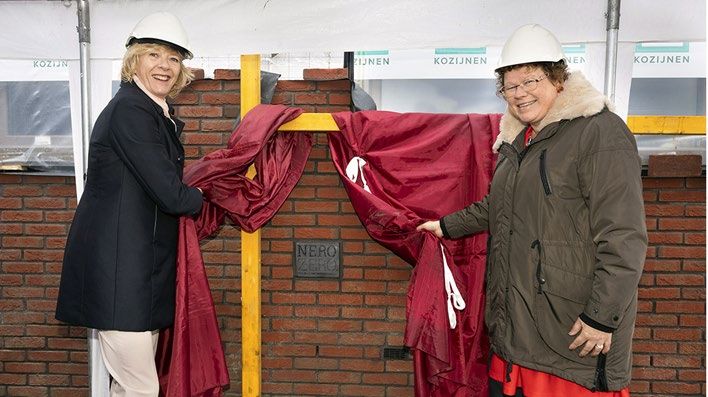
10 || Introduction                                                                                                                                                                                                                                                                   Introduction || 11

     •     A data ontology9 model to store a “state” of a digital world - past, present and predicted.                                                   In addition the Digital Twin should provide a common point of clean, structured and
     •     A way to represent a data state and ontology to humans - e.g. a visualization is optimal for                                                  consistent data access for other systems to connect to, especially analytics and simulation
           human cognition and critical to real world action, and lastly                                                                                 systems that can help to optimize the digital world and so on to the actual world. This data
     •     The tools and methods to work with the DT state model and apply AI, analytics and simulation                                                  interaction with simulation and analytics systems should be 2 way of course to allow new
           creating future scenarios for understanding, and so optimize for the future.                                                                  predicted or possible states to be communicated to the computer and humans.

In general the challenge we have seen in creating DT’s (even before they were so aptly                                                                   But as data is collected to form a current picture or “State” of the world in a digital form, the
named) over the many years is one of data integration between systems to bring all the                                                                   need for humans to be able to see this state - a large collection of different data about the
disparate data representations of things together. Mark Thomas believes very strongly in the                                                             world – becomes a challenge. It is not enough to get a written report or a 2D plan drawing
value of a pure ontological approach to this process. Using this approach provides a system                                                              of the world 1, 2 or even 3 dimension data representations of the current state of the world.
independent way to structure and join data. A good use of ontology for data integration                                                                  These are inefficient for complete human cognition and understanding.
simply asks the question of any incoming data set (static or dynamic):
                                                                                                                                                         The compelling nature of animated interactive 3D graphics has created a breakthrough how
- Can we find the following information in this data to map to a universal ontology?                                                                     we can visualize the actual world in all its complexity and possibilities, however it is important
- What are the “things” that are referenced in this data? E.g. walls, valves, doors, pipes,                                                              to remember the place that visualization has in the Digital Twin space.
supports?
- What are the attributes that are referenced to these things? Size, manufacture,                                                                        Some Problems with “Visual First” Approaches to Digital Twin
temperature, pressure, date last maintained?
                                                                                                                                                         Implementations
- What are the implied relationships between things? Parent, child, connected to, supplied
by? Links to other data objects (Media, sound, video, documents)                                                                                         A common problem with many attempts to create Digital Twin Technology in the broader context
                                                                                                                                                         is the fascination with 3D graphics. So often the approach has been to take hold of a CAD or
- When and where are these things and their data? Lat Long, Elev, relationship to another
                                                                                                                                                         BIM or GIS file model and then attempt to force fit the data about the thing this single graphic
coordinate system, time of creation, destruction date, time to build?
                                                                                                                                                         representing the thing in one state of its lifecycle – usually the engineering design phase.
And lastly
- What are the valid visual representations of this thing? Point, Line, Polygon, 3D model,                                                               There are multiple problems with this common approach. `Things’ have a life cycle and the
photo, LIDAR scan, Point cloud? Different resolutions of any of the above? Different file                                                                visual representation is NOT the essence of a thing. It is only as useful as the specific use
formats of any of the above?                                                                                                                             case at a specific time.

It is pleasantly surprising how thinking about things and their generic attributes relationships                                                         The essence of a thing need, and should be, no more than some kind of unique identifier (GUID
etc. provides a way to systematically connect data from different sources and adds a layer                                                               – Global Unique ID10). A graphic or 3D model is not a useful consistent GUID but is treated as
of simplicity and calm to data integration problems. The reason for this pleasant surprise                                                               one by many BIM and Digital Twin models. GUID management is absolutely essential to Digital
is that the idea of universal ontology is as old as the Greeks if not older. The idea of                                                                 Twin data management allowing changes and updates to be processed. Using a graphic as the
ontology attempts to describe the world in a systematic way that is purely logical and so both                                                           absolute definition of “unique” is simply inadequate and fails in too many cases.
computer and hopefully human friendly. Complexity can be resolved by simply categorizing
the world into things we care about and their nature, and the goals we have in managing or                                                               CAD files or graphics containers are designed for managing data or data changes over time
interacting with them.                                                                                                                                   let alone changes to the very structure of the data – That is what database technology is for.
                                                                                                                                                         CAD files are typically unable to contain multiple taxonomies (or hierarchies) and so
In a practical sense the adoption and availability of open API’s between systems allows for                                                              reordering things depending on use case or context is near impossible. Users get stuck
such ontological conversations to happen between computers now and not just people,                                                                      with the engineering hierarchy which is different from the manufacturing hierarchy which
making complex data integrations possible and the amalgamation of vast and varied data                                                                   is different from the parts ordering structure which is different from the valid configurations
into a representation of a “Digital Twin”.                                                                                                               hierarchy.

                                                                                                                                                         10 In the world of web ontologies and Linked Data, the identifier is often an HTTP URI instead of a GUID. Since the essence of the Web needs to allow
9 “An ontology is a formal, explicit specification of a shared conceptualisation” [2] -conceptualisation: classes and types of relations, terminology,   different people to start talking about the same physical “thing”, they might end up with different URIs. This principle is called the “no-unique name
describing a domain of knowledge                                                                                                                         assumption”.
- formal and explicit specification: applies a machine-readable formal language combined with logics                                                     E.g. the URI for Barack Obama in DBPedia is http://dbpedia.org/resource/Barack_Obama while in Wikidata the URI is https://www.wikidata.org/entity/Q76
- shared: result of a collective effort, is shared in a community and is independent of implementations                                                  Ideally, there’s only one identifier in the network of data storages for each real “thing”, but in practice this is often not possible because URIs can
[2] R. Studer, V. R. Benjamins, and D. Fensel. “Knowledge Engineering: Principles and methods”. In: Data & Knowledge Engineering 25.1-2 (1998), pp.      be minted by different systems in a network in parallel. Links between URIs that denote the same thing can of course be established, to reduce the
161–197. doi: 10.1016/S0169-023X(97)00056-6.                                                                                                             semantic heterogeneity.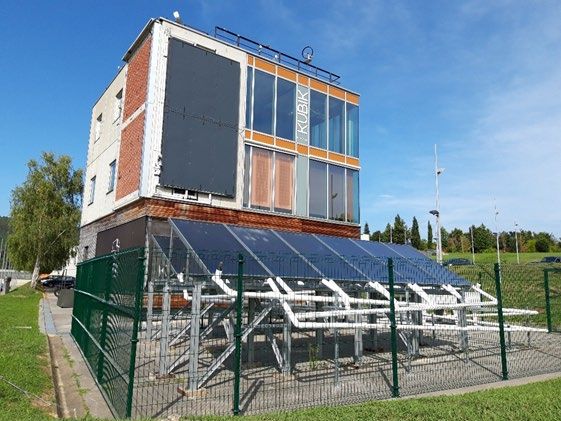
12 || Introduction                                                                                                                                        Simulation across building life cycle || 13

                                                                                                  2.-SIMULATION ACROSS
In short 3D graphics have no business being the basis of Digital Twins they are merely a
representation tool that should be driven by a pure ontology model.

In practical terms of BIM meets GIS meets IoT meets finance etc. There can be only one
common language. One based on data ontology modeling. Not on pre-structured CAD

                                                                                                  BUILDING LIFE CYCLE
or GIS file formats or ERP hierarchies with no concept of instance context within larger
structures or the world.

A good Digital Twin is more like a dynamic map of connections between things than a static
mega structure or 3D visualization. The latter are simply possible representations of the DT
which may change depending on use case or the current state of the world that is mirrored,        Simulation is today a wide set of techniques to reproduce physical behavior using mathematical
past present or predicted.                                                                        resources. We can have 0D-1D problems, where the space representation is not considered,
                                                                                                  or we can simulate complex 3D fluids or solids using FEA analysis. These methods can be
And lastly a good Digital Twin platform is one that can be used by anyone (with some              combined and we could get sets of models connected exchanging information during time.
training, i.e. not a services contract) and one that can easily and naturally federate multiple
separately created digital twins from a machine level to an organization level to a city to a     In a building a primary analysis is how the structure will be responding to climate, seismic or
state and a national level.                                                                       loads of any kind. For this we can use advanced FEA software to represent the building in 3D
                                                                                                  and ‘simulate’ how the building could be responding to loads in different scenarios.

                                                                                                  When 3D representation could be too complex or just because we want to simplify the
                                                                                                  problem we can use mathematical simulation. In this case the ‘big’ problem can be cut into
                                                                                                  pieces (‘components’), and these pieces connected by ‘ports’. This could be the case of
                                                                                                  energy problems where we have to consider temperatures, fluids, walls,.. In the end I can
                                                                                                  represent by equations each of this problems without the detailed 3D geometry.

                                                                                                  Mathematical simulation gives us a huge flexibility to represent any system as soon as we know
                                                                                                  its behavior, whether using equations or a graph. Many equipments can be well represented by a
                                                                                                  performance curve, and using this curve we can create a ‘component’ with inputs and outputs.

                                                                                                  Traditionally these techniques have been used for complex systems, like the ARES MODULE
                                                                                                  at International Space Station life support system.

                                                                                                                                Figure 1: International Space Station ISS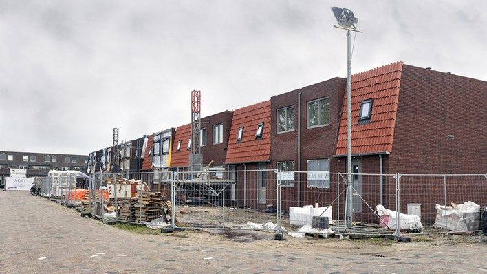
14 || Simulation across building life cycle                                                                                                                   Simulation across building life cycle || 15

A life support system comprise many devices and it would be impossible (or not practical)
to represent the fluids interacting with machinery. Instead we used equations, we represent
each device and we can connect all of them reproducing the dynamics of the system with
great detail.

                                                                                                                                    Figure 4: Pilot NERO ZERO, Delf, 2020

                               Figure 2: ESAColumbus module at ISS

                                                     In a building we can do the same. If
                                                     we consider one of the demo pilots of
                                                     SPHERE (TNO pilot at Delf, Holland), we
                                                     can ‘extract’ all components of discipline
                                                     ventilation: spaces, doors connecting
                                                     spaces, home ventilation machine and
                                                     pipes for the 4 circuits of the network                         Figure 5: Spaces, doors, diffusers, pipes, and home ventilation machine
                                                     (inlet, air distribution, air extraction and
                                                     outlet to the roof).                           We will connect this ‘discipline’ with others, but we are able to separate these ventilation
                                                                                                    components from the rest of the building. This capacity of dividing a big problem into smaller
                                                                                                    ones is essential to solve a big building. We could be creating separate models by discipline
                                                                                                    and floors as well. There is no limitation.
      Figure 3:TNO demo pilot SPHERE project
16 || Simulation across building life cycle                                                                                                                       Simulation across building life cycle || 17

The simulation model of the system described could be as follows:                                        In case of a thermal model the ports are red and we see
                                                                                                         walls, windows, doors, slabs and cover. And thermal ports
                                                                                                         can be connected with other floors, rooms and spaces in
                                                                                                         ventilation.

                                                                                                         A single component of a wall is represented graphically by a
                                                                                                         symbol.

                                                                                                                                                                           Figure 8: Component of a wall type IW01

                                                                                                         This graphical symbol has a mathematical representation behind, which is as follows:

                         Figure 6: View of components of ventilation simulation

                                                     As we see each component is connected
                                                     with others using ‘ports’. There are fluid
                                                     ports, thermal ports, control ports,... I see
                                                     big arrows as well connecting ports of
                                                     different diagrams (in this case we have two
                                                     diagrams, one for each floor). This model in
                                                     figure 6 is representing ventilation, but if we     			                 Figure 9: Mathematical description of wall type IW01
                                                     represent thermal problems the model would
                                                     be as follows:
                                                                                                         We could create new components, increasing the library items available to build the
                                                     Figure 7: Thermal model of one space for TNO demo   models. These libraries are essential to make all this process economic and fast. Hence it is
                                                     pilot                                               important to prepare in advance catalogs of equipments to be used in projects. And this is the
                                                                                                         new concept ‘SIMBOT’ made up in SPHERE EU project. A SIMBOT would be just a model of
                                                                                                         one equipment available in the market.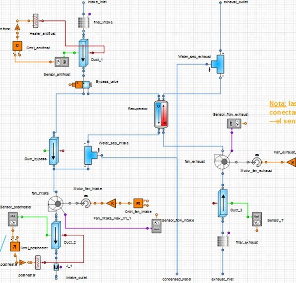
18 || Simulation across building life cycle                                                                                                 Simulation across building life cycle || 19

In the case of the ventilation model the home ventilation machine (FLAIR400 of brand   The SIMBOT reproduce how the machine is inside: it has two ventilators, recuperator,
BRINKS) is represented by the following component:                                     bypass, sensors, control signals, filters, ... We would be able to represent the functionality of
                                                                                       the Flair400 with high detail. All this components are condensed into a one single symbol and
                                                                                       we can play with that symbol is future models.

                                                                                       Implementing standard SIMBOTs to be used massively is posible thanks to standards as
                                                                                       FMI, but it is important to define standard ports as well. This task could be performed by the
                                                                                       Building Digital Twin Association recently created, providing public connectors to be used
                                                                                       with SIMBOTs published by whether fabricators or end users (simulation engineers).

                                                                                       Similar to equipments we can create SIMBOTs representing human models. IN SPHERE
                                                                                       EU project human models for ventilation and thermal disciplines have been used interacting
                                                                                       with spaces. Using a multiplexor these human models can move around the bulding and they
                                                                                       may be specific. This human models will be open and public by the BDTA, in such a way any
                                                                                       simulation software could use the models as standard test. More information about these
                                                                                       human models will be avilable soon, but in order to be used in real time these models have
                                                                                       specific design using the information of a CPX test11.

                                                                                       Complexity and Size of the Models
                           Figure 10: Home ventilation machine component               Adding many components and disciplines would create a huge mathematical model. Is
                                                                                       such a model affordable? Well, it depends on how the component is created and what
                                                                                       is the final use of the model. One single component consuming many equations and
The component itself (SIMBOT) internally is described by another simulation model:     convergence problems would make impossible to use that model in real time. So special
                                                                                       care must be taken when designing the mathematical complexity of the models. If we
                                                                                       want to use the models both for design, commissioning and exploitation of the building
                                                                                       components must be designed specifically for real time. This does not mean to lose
                                                                                       precision, but simply don´t describe mathematically some of the processes involved
                                                                                       internally in the equipment, and in turn to use plots or performance curves. Details about
                                                                                       how the equipment performs internally when we want to see the performance of a whole
                                                                                       building is a mistake.

                                                                                       In SPHERE project we have tested models of buildings of about 10,000m2 with capacity
                                                                                       for being executed in real time (this means they converge in less time that the step used
                                                                                       to register the main ambient parameters of the building, which usually are around 600
                                                                                       seconds). But special care must be taken with complex machines with crossed fluid flows.

                                                                                       Model for Design, for Commissioning and Model for Real Time
                                                                                       Control
                                                                                       One of the great advantages of using mathematical simulation with building digital twins is
                                                                                       that they can be useful for design, commissioning and the day by day use of the building.
                                                                                       The same mathematical model means equations but we can play with boundary conditions
                                                                                       and controls around the same core model.

                                                                                       11Cardiopulmonary Stress Test (CPX)
                            Ilustración11: Flair400 SIMBOT programming
20 || Simulation across building life cycle Simulation across building life cycle || 21
‘Design’ phase means that we have to introduce synthetic meteo and occupation, and we Less Sensors, More Intelligence
can consider many alternative options. There are several resources for historical meteo
or TMY files, and occupation may be organize with schedules considering different family To use technology for life support of the ISS could seem excessive, but there are some
configuration or occupants of the house. interesting points to consider. If we have the behavior model of a building we can have
less sensors in the field, and we can detect when a sensor is malfunctioning. Having fewer
The final end point of a simulation ‘for design’ would be an optimum selection of systems and sensors in a house is desirable as it is not an intensive industrial factory full of engineers. It
cost, or comfort expected calculation. We can get this information with detail every 10 or 15 is not only a problem of cost, it is just that they don´t survive for ever. With simulation we can
minutes, studying dynamics of the buildings and not only static behavior. We could check detect that something is not going well not only based in one temperature sensor, but in the
how predictive meteo control could improve the energy consumption, or how long does it rest of the values of the building.
take to heat the house after a long weekend outside.
And we can derive many new magnitudes from sensors. Magnitudes which are not
Once decisions have been taken and the building is ready for construction we can use ‘the measured. For example euros that are flowing across a wall, money we are recovering at the
model’ to test parts of the building. The model would be connected whether as ‘software home ventilation machine, virus risk due to lack of ventilation or thermal comfort of human
in the loop’ (SIL) or ‘hardware in the loop’ (HIL) with the rest of the installation. With some A, B or C. Simulation can be used as a calculator translating the engineering magnitudes
simplification, SIL could be to have the model as ‘virtual building’ working against the physical (not understandable for the majority of the humans) into economic magnitudes which may
control system implemented in site or in the lab. In this way I can test in advance the controls be understood by anyone. I could not understand what means 1.2 W/m2 of transmittance,
and train the operators of the control room. Sensors are virtual outputs from the simulated but for sure I can understand much better that the window is losing 1€ every day. Around
model of the building. Finally simulation can be used for commissioning when construction this stupid consideration may be a catalysis of many user investments improving the house
process has finished, checking that installations work as it is expected. quality or how to open/close windows.
During the life of the building the simulation model can be used as well, and this may open Simulation Deck Concept
many new challenges, whether by measuring and increasing comfort or by controlling and
reducing the energy consumption. People prefers to pay money to get more comfort, and just Once the mathematical model of the system is finished the interface with humans may be
paying for less Kwh may be not totally understood. In any case to have both things is not a simplified. In the same way we can create exe files to run in parallel to the control/monitoring
contradiction. system we can implement a table of input/outputs to be used for testing. This is call a deck
and it can be integrated in excel.
Meteo and Occupancy in Real Time
The two key problems to use simulation models for real time is just how to input inside the
control system the actual and predicted meteo and occupancy. The control system may be
just a monitoring device and a PLC for collecting sensors and digital signals.
Today in most of the countries meteo information is well localized and predictions respond
quite well to reality. Instead of looking at the sky we check the phone to see if it is going to
rain or not in the next couple of hours, the probability in percentage and how much rain in
mm. To get this information (and prediction) from the web is something extremely useful and
we can introduce the values in the ‘control system’, and this control system is connected with
our simulation model. This simulation model is an exe file which even may be running locally
in the same machine than the house controls, or it may be running in the world wide web.
Optimizing the simulation components provide compact executable routines which may be
integrated in very small electronics. The exchange of inputs and outputs may be reduced to
those values we are interested, which means we don´t speak about hundreds but twenty or
thirty values in a house, not more. And we exchange these values every 10-15 min with no
stress for even a small Raspberry Pi 4B.
Figure 12: Deck of DEMO pilot TNO ventilation22 || Simulation across building life cycle Simulation across building life cycle || 23
In the figure we can see the deck generated for the ventilation system of the TNO demo pilot
of SPHERE project. Inputs are the manual setup of the Flair400 home ventilation machine
and the location of the family (‘Value’ is the room number). Outputs are CO2 values in the
living room and the two bedrooms, flows between spaces (underneath doors), and some
parameters of the home ventilation machine (some of them calculated, not measured).
A deck is an excellent way to communicate models before implementing the real time
platform and to define which values are necessary to input and output from simulation
executable to the control/monitoring system.
2.1.- Energy Simulation and BDTs, Reducing the Gap
Energy Performance Certifications were introduced in the framework of European
legislation for the first time in 2002. Following the requirements of the first Energy
Performance Buildings Directive (EPBD)(2002/91/EC), all the member states had to
introduce certification schemes for the energy performance of buildings. The objective of
this Directive was to ‘promote the improvement of the energy performance of buildings
within the community taking into account outdoor climatic and local conditions, as
well as indoor climate requirements and cost-effectiveness. The Energy Performance
of Buildings Directive (EPBD 2018/844/EU)12, has amended Directive 2012/27/EU13,
sending the political signal for modernising the buildings sector using technological
improvements in building renovations supporting at least 32.5% energy savings and at
least 32% energy from renewable sources by 2030 in line with the Energy Performance
of Buildings Directive (EU) 2018/200114. Figure 13: Spanish certification tag
The EPBD was the first EU directive that prescribed that EU Member States should apply
In another way, The EPBD defined that member States have flexibility in the software tool
a methodology at a national or regional level to certify buildings’ energy performance
to perform the calculations and in all the related aspects of practical implementation. This
based on a general framework. Although the initial scope was to define a common frame
flexibility has led to a non-so homogeneous energy certification implementation as it was
for all the countries, the implementation of the EPBD at the country level has varied
initially expected. However, some suggestions include operational data, such as actual billing
significantly in the introduction and performance level. So, the Directive did not contain
data on EPCs to overcome the performance gap and ensure that the EPC reflects actual
requirements or guidance related to the ambition level of such conditions. Consequently,
building use. However, the use of billing data directly on the EPC, such as the annual energy
building regulations in the various Member States have been developed by using
cost or the annual consumption, would capture the effect of occupant behaviour as well as
different approaches (influenced by different building traditions, political processes,
the performance of the building, and would therefore move away from EPCs comparing
individual market conditions, and technical limitations for establishing the energy
building behaviour as such. In addition, there are potential data protection issues with billing
parameters). Additionally, it resulted in different ambition levels where cost optimality
data included directly on the EPC as this is more personal to the building occupant.
principles could justify higher ambitions in many cases. These big differences have made
it difficult to get a homogenous vision of implementation at the European and cross-
Next-generation eEPCs shall adopt a single neutral approach that will integrate
comparisons countries. This problem presents an opportunity for the concept of the
systematically and accurately information collected and processed under the digital twin
digital twin. This multipurpose solution can serve to create a common framework from
to integrate different energy performance approaches, ensuring data quality and avoiding
which to support EPCs.
assessment errors highlighted in several papers. Digital Twin will tackle this problem by
introducing a methodology that will allow, with building occupant consent, smart meter data to
be used in conjunction with other data, such as internal and external temperature, to model
12 Directive (EU) 2018/2002 of the European Parliament and of the Council of 11 December 2018 amending Directive 2012/27/EU on
energy efficiency (OJ L 328, 21.12.2018, p. 210) the thermal performance of a building. For that, the proposal is coupled the digital with a new
13 Directive 2012/27/EU of the European Parliament and of the Council of 25 October 2012 on energy efficiency, amending Directives concept of direct method of calculation according IEA BESTEST15. This option will reduce the
2009/125/EC and 2010/30/EU and repealing Directives 2004/8/EC and 2006/32/EC (OJ L 315, 14.11.2012, p. 1).
14 Directive (EU) 2018/2001 of the European Parliament and of the Council of 11 December 2018 on the promotion of the use of energy
from renewable sources (OJ L 328, 21.12.2018, p. 82). 15 International Energy Agency Building Energy Simulation Test and Diagnostic Method, https://www.nrel.gov/docs/fy08osti/43388.pdf24 || Simulation across building life cycle Simulation across building life cycle || 25
performance gap by allowing ‘as built’ performance data to be used in an EPC rating while
also factoring out the effects of occupant behaviour so that the EPC rating remains reflective
2.2.- BDTs During Design and Construction
of the building itself. It could also simplify the process of generating an EPC and improve Digital Twin Construction (DTC) is a paradigm for the construction industry in which
the repeatability and accuracy of EPCs. Any use of smart meter data would require the production is planned and controlled with the support of extensive data collected from the
householder’s consent, in line with data access and privacy requirements. This methodology supply chains and the site which provides comprehensive situational awareness for all16.
will better understand the market demand for these technologies and possible routes for their Monitoring technologies of various kinds – including audio, images, RFID and BLE tracking
development and implementation. systems, equipment ‘black boxes’, IOT sensors – are applied to supply real-time tracking
of the physical conditions on site. The raw data is processed within the context provided
The building models used in EPC schemes are quite precise; a more detailed modeling of by product designs (mainly BIM models) and process plans (production facilities, logistics,
the archetypes allows for even more accurate simulations, considering for example the real schedules, budgets) to generate useful information that describes the status of the project at
position of the windows, shape of the roof, or real building schedules. However, this information any time. Comparing the current project status to the project intent information allows one to
is too complicated to get (LoD 300 or 400). In addition, 3D models simplify the process of draw conclusions about current performance, in terms of the quality of production flow, safety
obtaining the real geometry of the buildings in a district greatly. The difficulty in producing performance, quality of the products built, and schedule and budget progress.
detailed building models should solve using real measurements of buildings to calibrate or
correct simplified building energy models. So, BIM solution. These detailed multi-zone models But how can that information be leveraged to improve production planning and control?
should be developed in parallel to a building monitoring campaign of the archetype buildings, This is a key question, whose answer will determine the value of Digital Twin Construction
which would allow model calibration and the development of the energy baselines. platforms.
In conclusion, using BIM for geometric and constructive description and measurements In theory, better situational awareness, i.e. knowing what is happening on and off site with
integrated in BIM for operational description, the double certificate can be obtained: energy great detail, supports better decisions by people when it comes to making changes to
performance certificate with the standard user and real user. Standard user is useful to the production system on site. Managers may decide to add or remove a piece of major
evaluate the building when it is going to be bought or sold (conventional use of EPCs). Real equipment, such as a crane; to request a subcontractor to work overtime; to change some
user requires measurements and it is useful to consider the user behaviour and the final use aspect of a building’s design; etc., all dependent on the scope and time resolution of planning
of the building. This option should be used when the building is going to be renovated (new and control cycles. Yet these are highly complex systems, and good decision making is
use of EPCs). also dependent on the ability to predict future outcomes for any given intervention.
Construction process simulation provides an effective solution. A good process simulation
In conclusion, the recommended road map of EPC presents three levels. First, it is the tool can help determine the range of outcomes expected given any starting scenario and a
mandatory scheme using the standard user. Second requires the actual energy situation schedule of changes planned over time. It can provide estimates of the probability of each
of the building (real user), and it is used when you are going to renovate the building. The possible outcome, thus shedding light on the risks involved.
third level represents the last step, the smart management of the building. The second and
third levels require the use of calibrated energy models or inverse characterisation models. In the DTC context, simulation software can exploit the current project status information to
Building energy models need to be calibrated at the second level to reduce the performance set up the starting conditions – what work in the project has been done, which objects are
gap and consider the actual thermal behaviour. Automatic calibration allows assessing completed or under construction, what resources are present and what are the trajectories
the cost/benefit of improvement measures in rehabilitation interventions. It is interesting of their production rates so far. It can also exploit archived records of previous DTC
to highlight that calibration of a detailed direct model lets to evaluate the potential of records to learn patterns of production, potential bottlenecks, and possible product/process
complementary or alternative Smartness actions to conventional improvement measures. At interdependencies that cause fluctuations in production flow. Critical path method simulation
the third level, the inverse characterisation model provides the baseline for verifying savings tools might simply extrapolate deterministic construction network schedules into the future
when measures are implemented. The inverse characterisation joined with the direct model using distributions of predicted activity durations. Richer, more accurate simulations would
provides a new tool that configures the digital twin. Also, the tool allows optimal energy/ apply agent-based simulation to progress construction activities into the future with dynamic
economic decision-making in the adoption of smartness adoption. assessment of production constraints for each task as work progresses. The latter are far
more likely to reflect realistic patterns of behaviour because the underlying model applies
concepts of production flow in construction17.
16 Sacks, R., Brilakis, I., Pikas, E., Xie, H., and Girolami, M. (2020). ‘Construction with Digital Twin Information Systems’, Data-Centric
Engineering, Vol. 1, pp. 1-26.
17 Sacks, R., (2016). ‘What constitutes good production flow in construction?’, Construction Management and Economics, Vol. 34, No. 9,
pp. 641-656.26 || Simulation across building life cycle Simulation across building life cycle || 27
With the ability to test ‘what-if’ scenarios that reflect the range of actionable decisions open component, in case of other details of the building (mainly networks) they may be simplified
to them, construction managers at all levels will have valuable information at hand to aid in the simulation model. But this depends on the library created in the simulation scenario,
them in planning and controlling production both at the start and during the execution of their so different libraries could have different mapping tables of entities versus simulation
projects. Thus, simulation builds on the first major advantage of DTC, situational awareness, components.
to give construction managers a second significant advantage – a layer of predictability.
The power of predictive simulations of construction processes can be exploited further Instead of fully automatic translation from IFC to simulation model we could think on a
by wrapping simulations within optimisation routines, such as genetic algorithms. In this semiautomatic translation, preparing the IFC models to be translated by disciplines and
way, DTC software systems could not only advise managers on the likely outcomes of groups, or just to program ‘checking’ routines instead of ‘translation’ ones.
interventions they propose, but they could also devise new sets of interventions that are likely
to have superior outcomes.
2.3.- BIM Models and SIM Models, how to Improve the
Linkage
Before performing any simulation a design or at least a basic concept of the building must
exists. A BDT Manager (external to the simulation) must define the starting point. And one
way we exchange a building ‘design’ is using an open BIM structure (whether as an IFC
file or the IFC data structure in other formats). We could be using more traditional ways to
represent the building, form handmade drawings to CAD floor plans, but the power of the IFC
standard is to bring together geometry and properties with a great level of definition.
But even having a good graphic definition and lot of properties scope of simulation may need
an amount of information and disciplines that the designer is not able to supply. So BIM
models many times are not correct, they don´t have the properties we need for simulation,
Figure14: IFC model of ventilation network; ‘SUP_5’ component highlighted
the properties that include are senseless and even they don´t have basic entities we need for
the simulation, as spaces, installation networks and similar. They are ‘designs’, not rigorous
‘engineering projects’. The BDT Manager role would be coordinating and correcting this
process in order to be as closer as possible to a defined project.
In any case it would not be fair to say that BIM is not bringing an advanced and great
communication tool for architects and engineers. Problems are more evident and they are
detected in minutes, even for non construction professionals. We are able to get simulation
teams of physicians working well with architect´s 3D buildings.
To define how a BIM model must be delivered is a general question in many organizations
today. In case of SPHERE project we decided to have a flexible process in which we were
receiving IFC models creating components and simulation models based on different ways
to design the demo pilots. Attending disciplines we generated several ‘checking rules’, first
for a basic global ‘model correctness’ and later deeper and rigorous criteria for ventilation
installations. Figure 15: Simulation component SUP_5
Today it is difficult to find good IFC models with installations. Preventing this problem we
were testing synthetic models with detailed installation of ventilations, testing the exchange As we see in the two images above, the IFC entities highlighted of the network finally are
between IFC and simulation. Even in the case of well calculated and detailed models a single simulation component (SUP_5). And it is likely unavailable connectivity between
some problems must be considered. Depending on how library components are generated components, as it is not exported in most of the CAD programs. So translation may be a hard
relationship between IFC entities and simulation components is not 1 to 1. If we consider route to follow, and probably not given the expected results.
networks runs as ‘one simulation component’ the entities in the IFC model may be several
straight pipes and elbows. Whereas equipments are easily associated to one single28 || Simulation across building life cycle Simulation across building life cycle || 29
More important than translation is consistency on data. Simulation components must Precision and accuracy depends on several factors. Accuracy refers to how
have faithful parameters taken from whether the BIM model or reality. Consistency checks close measurements are to the “true” value, while precision refers to how close
are critical and necessary, and it is not a wonderful activity in which everyone wants to measurements are to each other. A thermal sensor may have plus minus 1 degree C of
participate. However as important as creation of the model. Checking routines would have precision and they are usually accurate. But CO2 sensors may have plus minus 50 ppm
much more profitability than translation. precisions (normal values of 400 to 850 ppm) and they are very inaccurate, so we need
frequent calibration. What is important is that ‘monitoring’ is not ‘reality’, so we must
Many software programs tested during the development of SPHERE project were preparing consider statistical errors and deviation for taking (or not) decisions. Many problems
the simulation from inside the CAD. This is the case of ESBO18 from inside DDS-CAD19. Or arise from over controlled systems.
the case of CypeTherm from inside the Bimserver.center20 environment. Other programs
may be able to create/import the model, but always with great control of details to ensure Measurement may be sampled every second, but finally it is going only to transmit one
consistency with calculations (as Simergy21). Most of them are conceptual programs and not value every 10 to 15 minutes. Sensors today can perform many low level operations
designed to be used in real time, with full detail of the building and controls. So oriented only providing treated values at low cost. Transmitting those values can be executed by
to the design phase of the life cycle of a building. cable or a series of frequencies and standards, and at the end we will have a hardware
and software system, reproducing historical data and tendencies in a human machine
In advanced simulation oriented to real time exploitation of the building we need additional interface. And perhaps together with monitoring we may have a controller (PLC) and
information to what we can extract from IFC models. Re-construction of simulation models simulation engine integrated.
need schedules, controls, performance curves, connections, ... We are still far away from Discussion about where and how to locate these systems may have a privacy
defining everything at the IFC model. So where to find this information? Meteorological implication and it will be treated at the chapter of trustworthiness and privacy.
input and occupancy during design can be represented with historical data (or TMY files) or
schedules for human models. But in real time those data must be collected and directed to Additionally to resident instrumentation it will be necessary to use some instruments
the simulator, so we need a explicit way for doing it, hardware and software. for testing air tightness, flow in diffusers or noise of ventilations systems. As it has
been described in detail by TNO 22 , SPHERE partner, for performance contract of
And going back to the conversion problem of BIM models into simulation we should consider ventilation systems.
the way back: using simulation to update or illustrate BIM models. This should be an easier
task and more graphical, adding value to the 3D models in real time. 2.5.- Virtual Commissioning
2.4.- Monitoring the Real Building In 2017 the team of PhD Enrique Blanco Vinuela, Control Engineer and Head of the
Control Systems Engineering Section at CERN Laboratory, had to take a decission
Monitoring a building is a sampling problem and estimation of what we considers ‘true’. about the LHC (Large Hadron Collider) upgrade. It had been operational since 2008
Buildings with high value per square meter can have attended and sophisticated automatic and for 9 years no major improvement was done on ATLAS and CMS HVAC plants.
sensors and equipment, but this does not happen in residential. We face not only a problem They had to solve an obsolescence problem (SCADA was not supported anymore) and
of fewer sensors, they may be cheaper and not attended or maintain at all. How could we PLCs were at the end of life. They wanted to migrate control to the CERN UNICOS
justify an investment on those sensors? framework and it would be interesting to take into account all the experience gained
during the LHC operation to improve operation and availability. Lot of manual actions
If we want to control our residential environment monitoring or measuring reality is necessary. were necessary at that time.
We must detect how is exterior temperature to decide whether to switch on the heating or
not. It may be done by an automatic device or manually, but the fact is that temperature Due to very strict conditions to carry out the smooth transition and a limited time for the
must be measured. How many sensors or accuracy and precision is another question. new installation they decided to go ahead with a “virtual commissioning”. It could be
The number of sensors should be adapted to the number of controlled spaces. And done off-line, they could be simulating the installation testing different control strategies
residential construction always follows a standard number of rooms and spaces. So we and it could be useful for training operators as well. They had to develop a physical
speak of less than 10 ambient sensors and those which are included in equipment as a home model of the building first, in order to use it against the new control system to be
ventilation machine. They are not hundreds. implemented.
18 https://www.equa.se/en/esbo
19 https://www.dds-cad.net/
20 https://bimserver.center/en
21 https://d-alchemy.com/products/simergy 22 ‘Commission and performance contracting of ventilationsystems in practice.Determination, analyses and consequences forpractitioners
and contractors’. By Wouter Borsboom, Wim Kornaat, Pieter van Beek, Niek-Jan Bink andTimothy Lanooy.30 || Simulation across building life cycle Simulation across building life cycle || 31
Figure 17: CERN model: in orange control components
Figure 16: CERN CMS and Cavern
Figure 18: CERN 5 days simulation and validation
To implement their “artifact replica” they had to review P&IDs, Equipment datasheets, The new control system was at the same time developed by the Cooling and Ventilation
maintenance reports, duct routing, GA drawings, I/O lists, PLC programs, HVAC team at CERN. And more testing with PLCs at the lab was done to test communications and
commissioning reports, and finally of course they discovered inconsistencies, missing data new SCADA system. One day the new control implementation was decided and the new
and problems. This is not a task lazy engineers. As Dr. Blanco explains, they had to “use a control systems tested against the virtual process model. “Various operating scenarios were
shovel and pick and dig”23. performed over a period of several hours, including different discrete events: a step-by-step
start-up, gas detection, cap opening/closing, equipment failure and acknowledgement. These
For representing the basic HVAC components they developed a simulation library with the demonstrate the possibility to adapt the control automatically while keeping the regulation
software ECOSIMPRO24. Using the right connectors you can simulate mathematically all loops active”25.
fluids and ambient conditions, and equipment working in real conditions. They performed
many validations of the library even with real historical data they have recorded. Of
course not everything was perfect and manual adjustments were necessary due to lack of
25 https://cds.cern.ch/record/2306216/files/modpl02.pdf
information, but process model was finally responding as it was expected.
23 Virtual control commissioning for a large critical ventilation system: The CMS cavern use case, by Booth, William (CERN) ; Blanco
Viñuela, Enrique (CERN) ; Bradu, Benjamin (CERN) ; Sourisseau, Samuel (CERN)
24 https://www.ecosimpro.com/You can also read