Hydrodynamic constraints on the energy efficiency of droplet electricity generators

Page created by Nathan Schroeder
 
CONTINUE READING
Hydrodynamic constraints on the energy efficiency of droplet electricity generators
Riaud et al. Microsystems & Nanoengineering (2021)7:49
                                    https://doi.org/10.1038/s41378-021-00269-8
                                                                                                                                                               Microsystems & Nanoengineering
                                                                                                                                                                                                www.nature.com/micronano

                                     ARTICLE                                                                                                                                                    Open Access

                                    Hydrodynamic constraints on the energy efficiency
                                    of droplet electricity generators
                                    Antoine Riaud1, Cui Wang1, Jia Zhou1, Wanghuai Xu2 and Zuankai Wang2

                                      Abstract
                                      Electric energy generation from falling droplets has seen a hundred-fold rise in efficiency over the past few years.
                                      However, even these newest devices can only extract a small portion of the droplet energy. In this paper, we
                                      theoretically investigate the contributions of hydrodynamic and electric losses in limiting the efficiency of droplet
                                      electricity generators (DEG). We restrict our analysis to cases where the droplet contacts the electrode at maximum
                                      spread, which was observed to maximize the DEG efficiency. Herein, the electro-mechanical energy conversion occurs
                                      during the recoil that immediately follows droplet impact. We then identify three limits on existing droplet electric
                                      generators: (i) the impingement velocity is limited in order to maintain the droplet integrity; (ii) much of droplet
                                      mechanical energy is squandered in overcoming viscous shear force with the substrate; (iii) insufficient electrical
                                      charge of the substrate. Of all these effects, we found that up to 83% of the total energy available was lost by viscous
                                      dissipation during spreading. Minimizing this loss by using cascaded DEG devices to reduce the droplet kinetic energy
                                      may increase future devices efficiency beyond 10%.
                  1234567890():,;
1234567890():,;
                  1234567890():,;
1234567890():,;

                                    Introduction                                                                                        a voltage across the polymer layer13. In the latest studies, a
                                      Droplet electricity generators (DEG) are designed to                                              grounded metallic electrode is placed underneath the
                                    harvest the kinetic energy of rain droplets to power small                                          polymer and is connected to a small metallic strip on the
                                    wireless sensors. Despite a 100-fold increase in efficiency                                          top (see Fig. 1). According to the present under-
                                    over the past few years1–3, even state-of-the-art devices                                           standing2,14, this sandwiched structure then behaves as a
                                    only recover 10% of the kinetic energy of water4, as                                                biased capacitor. Upon contact with water, the capacitor
                                    opposed to the nearly 100% efficiency achieved by                                                    is discharged through the load, which releases the elec-
                                    hydroelectric dams.                                                                                 trostatic energy that was stored previously2. Meanwhile,
                                      Unlike dams, which extract energy from the mechanical                                             mobile charges accumulate at the water-polymer inter-
                                    work of water on the hydro-turbines, DEG, and more                                                  face. When the droplet recedes, those charges are
                                    broadly triboelectric nanogenerators (TENG) harvest                                                 detached from the interface and forced to return to the
                                    energy from charges accumulated on surfaces which are                                               bottom electrode4. While this model predicts the transfer
                                    then used to drive an electric current through an external                                          of charges through the DEG with a remarkable accuracy2,
                                    circuit by electrostatic induction5. In the case of DEG, the                                        it does not consider the hydrodynamic side of the picture.
                                    charges are spontaneously created by water at the surface                                           Yet, the harvested electrical energy accounts at best for
                                    of polymers6–10 by an electron-mediated contact elec-                                               10% of the initial droplet energy, meaning that, in our
                                    trification11,12. The process can be intensified by applying                                          present understanding, at least 90% of the droplet energy
                                                                                                                                        is unaccounted for.
                                                                                                                                           A comprehensive DEG model would consider (i) the
                                    Correspondence: Antoine Riaud (antoine_riaud@fudan.edu.cn)
                                    1
                                                                                                                                        electrical process at play, (ii) the hydrodynamics (iii) the
                                     State Key Laboratory of ASIC and System, School of Microelectronics, Fudan
                                                                                                                                        electrochemical charge stability and (iv) the electro-
                                    University, Shanghai 200433, China
                                    2
                                     Department of Mechanical Engineering, City University of Hong Kong, Hong                           hydrodynamic coupling. Since only 10% of the DEG
                                    Kong 999077, China

                                    © The Author(s) 2021
                                                        Open Access This article is licensed under a Creative Commons Attribution 4.0 International License, which permits use, sharing, adaptation, distribution and reproduction
                                                        in any medium or format, as long as you give appropriate credit to the original author(s) and the source, provide a link to the Creative Commons license, and indicate if
                                    changes were made. The images or other third party material in this article are included in the article’s Creative Commons license, unless indicated otherwise in a credit line to the material. If
                                    material is not included in the article’s Creative Commons license and your intended use is not permitted by statutory regulation or exceeds the permitted use, you will need to obtain
                                    permission directly from the copyright holder. To view a copy of this license, visit http://creativecommons.org/licenses/by/4.0/.
Hydrodynamic constraints on the energy efficiency of droplet electricity generators
Riaud et al. Microsystems & Nanoengineering (2021)7:49                                                                     Page 2 of 10

                                                                         viscous losses within the droplets during impacts, and
  a
                                                                         quantify the fraction of energy dissipated as viscous work
                                                                         and internal kinetic energy over the entire spreading step
                                                                         with no-slip and free-slip boundary conditions. According
                                                                         to this model, nearly half of the initial kinetic energy of
                                                                         low-viscosity droplets is lost as viscous dissipation in the
                                                                         lamella during spreading, regardless of the slip length,
                                                                         impact velocity and fluid viscosity.
  b                                                                        The stability of the lamella formed during the impact is
                                                     e–                  also a key concern for DEG. Intuitively, a splashing dro-
                                                                         plet releases some surface and kinetic energy in the form
                                                             Voltage     of ejected daughter droplets. Lamella breakup depends on
                                                                         a competition between a destabilizing suction and lubri-
                                                                         cation forces that lift it from the substrate, and a restoring
  c
                                                                         capillary force that pulls the liquid back into the bulk of
                                                                         the droplet24. When the restoring force is overwhelmed
                                                     e–                  by the other two, the lamella detaches and breaks into
                                                                         smaller droplets, resulting in splashing25. Even if the
                                                             Voltage     lamella remains stable and recedes, the liquid film itself
                                                                         may have thinned past its own stability limit and rupture
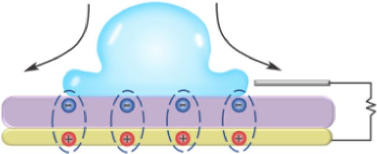
 Fig. 1 Droplet electric generator with charge circulation1,4,13.        into lower-energy liquid islands26.
 a The substrate is initially charged by the impingement of many           In this paper, we investigate the consequences of the
 droplets or other electrical forcing13 and forms charge pairs on each   hydrodynamic phenomena on the operating conditions
 side of the substrate. b Upon contact, the substrate capacitor is       and efficiency of DEG devices. Even though most DEG
 discharged through the load and the liquid. c During the recoil,
                                                                         devices can provide energy during the spreading of the
 trapped charges in the polymer are left behind, so that positive
 charges move back to the ITO to restore the charge pairs                drop1,2,4, it was experimentally observed that the DEG
                                                                         energy output peaks when the electrode is placed far
                                                                         enough from the droplet impact such that the electrical
energy is electrical4, we neglect the electrohydrodynamic                contact is established at maximum droplet spread1,2.
coupling and focus mainly on the hydrodynamic process.                   Therefore, we will restrict our analysis to these situations
Indeed, droplet impacts have been shown to obey the                      where the droplet spreads to its maximum extent before
same dynamics regardless of the susbstrate charge1. In                   touching the electrode. In the absence of electrical con-
this simplified view, the DEG hydrodynamics are exactly                   tact, the liquid provides no electrical energy during the
those of a droplet impacting an inclined plane. Even in                  spreading phase, and instead the totality of the energy is
this elementary picture, three effects compete to dominate               obtained during the receding of the liquid film. This is
the droplet dynamics: inertia, surface forces, and viscous               supported by a thought experiment where one would
dissipation. For a spherical droplet of radius a, density ρ,             drop a neutral conducting disc on the DEG. The biased
viscosity μ, surface tension γ falling at a velocity U0, the             capacitor would release the same amount of energy
ratio of kinetic energy to viscous work is approximately                 without any work from the disc. However, one would
the Reynolds number Re ¼ ρaU     0
                               μ , while the ratio of kinetic            need to overcome the Coulomb force between the mobile
energy to surface2 energy is connected to the Weber                      charges induced in the disc and the underlying polymer to
number We ¼ ρUγ0 a. During impacts, the liquid spreads                   detach the disc from the DEG, thereby attesting of an
into a thin lamella on the solid where most of the energy                electromechanical conversion during recoil. We note that
conversion occurs15. It was noticed quite early that a large             this energy is first stored as electrostatic energy in the
fraction of the droplet energy is lost during impact16. This             polymer until a new disc is placed to release it, thereby
loss was attributed to viscous dissipation within the                    completing the energy production cycle. The paper is
lamella16–18 until experiments of low-viscosity droplet                  organized as follows. The first part of the paper discusses
impacts on super-hydrophobic and slippery substrates                     the hydrodynamic limits of droplet impacts and illustrates
suggested that a large fraction of the energy was actually               these conditions with simple expressions from the
converted to internal kinetic energy (akin to turbu-                     extensive literature on normal droplet impacts15–21,23–29.
lence)19–21. Several recent works have since attempted to                Starting from the total energy available from a falling
bridge the gap between these two regimes15,22,23. The                    droplet, we will first estimate the maximum impact
numerical simulations of Wildeman et al.15 are of parti-                 velocity allowed for DEG devices depending on the dro-
cular interest for this study, as they show the location of              plet volume, then evaluate how this energy is converted
Riaud et al. Microsystems & Nanoengineering (2021)7:49                                                            Page 3 of 10

into surface energy and turbulent/viscous losses during        (ii) the growing rim at the edge of the lamella must not
the spreading phase, followed by the recoil phase. In the      reconnect with the solid afterwards. Interpreting condi-
second part of the paper, we complement this hydro-            tion (i) as a force balance yields the ejection ejection time
                                                                                                           pffiffiffiffi
dynamic picture with the electrical model of Wu et al.2 to     T e ¼ t e Ua0 25 from the real positive root t e of the fourth-
quantify the energy efficiency of DEG devices. We use           order polynomial:
experimental data from previous studies1,2,4 to explore
various operating conditions in a realistic setting (oblique       pffiffiffi pffiffiffiffi
                                                                     3   te                                               ð6Þ
impacts) and point out to possible improvements for this               þ      ¼ 1:1t e 2
                                                                   2Re We
technology.

Results and discussion                                         Upon ejection, the lamella lifts off with a vertical velocity
Fluid mechanics model                                          Vv. However, the ejected film also recoils with a speed Vr
Available energy                                               due to surface tension, which forms a fast-growing rim
  A falling droplet combines a kinetic energy K0 ¼             that may eventually reconnect with the solid, thereby
                                                               preventing splashing. A mass balance shows that the rim
 3 a ρU 0   and surface energy V 0 ¼ 4πa2 γ. Neglecting
2π 3      2

gravity, the minimum energy of a liquid in contact with a      grows at a rate bmax V r , which yields the second splashing
solid surface is obtained when the spherical droplet           condition:
intersects with the solid surface at the Young contact
               γ γ
angle cos θ ¼ sv γ sl . According to volume conservation,          V v  bmax V r                                         ð7Þ
           30
this yields :
                                                               where the constant bmax ¼ 0:14 was determined experi-
    V eq ¼ γAeq;cap  γ cos θAeq;base                    ð1Þ   mentally by Riboux and Gordillo25. Lamella recoil speed
     with : Aeq;cap ¼ 2πReq 2 ð1  cos θÞ                ð2Þ   Vr and vertical speed Vv at the ejection time are given by:

                                                                          pffiffiffiffiffiffiffiffiffiffiffiffiffiffiffiffi
    Aeq;base ¼ πReq 2 sin2 θ                             ð3Þ       Vr ¼    2γ=ρH t                                        ð8Þ
                                                                        sffiffiffiffiffiffiffiffi
                               22=3 a                                       ‘
     and Req ¼                                           ð4Þ       Vv ¼                                                   ð9Þ
                  ð2  3 cos θ þ cos3 θÞ1=3                              ρH t

where Aeq,cap and Aeq,base are the cap and base surface area       with ‘ ¼ K l μg V t þ K u ρg V t 2 H t                ð10Þ
of the droplet at equilibrium, and Req is its radius of
curvature. This ideal situation is never achieved in                           pffiffiffiffiffi
                                                                   and H t ¼ ða 12=πÞt e 3=2                             ð11Þ
practical DEG devices. Therefore, the maximum energy
available is obtained by subtracting this lowest possible      Here, Ht is the lamella film height at Te, and
energy from the initial energy:                                K l ’ ½6=tan2 αðlog ð19:2λg =H t Þ  log ð1 þ 19:2λg =H t ÞÞ
                                                               and Ku = 0.3 are two hydrodynamic coefficients for the
    E max ¼ K0 þ V 0  V eq                              ð5Þ   suction and lubrication forces that make up the lift force
                                                               ℓ. ρg, μg and λg are the gas phase density, dynamic viscosity
Maximum impact velocity                                        and mean-free path.
   The impact velocity is limited by two factors. On the          Even in the absence of splashing, the liquid film
one hand, the droplet may splash, but even without             formed after impact may still rupture. Surprisingly, even
splashing, the film formed by the impacted droplet may          though instability of static liquid films is a well-studied
still become unstable and rupture. We first recall the          topic31–33, film rupture immediately after droplet impact
splashing conditions according to Riboux and Gordillo25.       has received much less attention than the more specta-
While their study focuses on normal impacts, they mainly       cular splashing. Diman and Chandra26 have studied the
discuss the local dynamics of the lamella formed during        disintegration of liquid films formed after high-speed
the droplet impact, which suggests that, at least qualita-     normal collision between a droplet and a wall. While
tively, the splashing mechanism evidenced by these             their analysis is rather involved, and depends on the
authors may also be relevant for oblique impacts.              liquid-solid contact angle and the size of defects that
   When a droplet impacts a solid surface, it forms a          trigger the liquid film instability, experimental evidence
lamella that may recoil or break into droplets if splashing    over a range of contact angles, surface roughness
occurs. To splash, the lamella must satisfy two conditions:    and liquids suggest that the liquid film will rupture
(i) the liquid sheet must be ejected from the solid and        if the droplet impacts a solid wall above some critical
Riaud et al. Microsystems & Nanoengineering (2021)7:49                                                                                                 Page 4 of 10

                                                                 180                                                                                    0.96
                  3.0                                                                           3.0
                                                                 160
                                                                                                                                                        0.80
                  2.5                                            140                            2.5
                                                                 120
                                                                                                2.0                                                     0.64
                  2.0

                                                                                     U0 (m/s)
       U0 (m/s)

                                                                 100

                                                                 80
                  1.5                                                                           1.5                                                     0.48
                                                                 60

                  1.0                                            40                             1.0                                                     0.32

                                                                 20

                  0.5                                                                           0.5                                                     0.16
                                                                 0
                          25   50         75    100                                                           25         50      75           100
                                    V 0 (L)                                                                              V 0 (L)

 Fig. 2 The available energy and the limiting velocities for                   Fig. 3 Mechanical to kinetic conversion efficiency ηs (%)
 splashing and film rupturing. Maximum energy E max (in μJ)                     according to Eq. (14) for droplets impacting perpendicular
 available from droplets impacting perpendicular surfaces as given by          surfaces. The splashing (solid line) and film-rupturing (dashed line)
 Eq. (5). The splashing (solid line) and film-rupturing (dashed line) limits    limits are given by Eqs. (7) and (12). The markers + and ⋆ represent
 are given by Eqs. (7) and (12). The markers + and ⋆ represent the             the experiments of Wu et al.2 (spreading efficiency 17%) and Xu et al.1
 experiments of Wu et al.2 (energy available 19 μJ) and Xu et al.1             (spreading efficiency 30%), respectively
 (energy available 151 μJ), respectively

                                                                              Amax may be determined from experimental or simulated
Reynolds number Rec ’ 5000:                                                   droplet impacts, or using simplified models (see refs. 18,23
                                                                              for critical reviews on normal impacts, and ref. 22 for
    Re  Rec                                                           ð12Þ   oblique impacts). Among these models, Pasandideh-Fard
                                                                              et al.17 have provided a simple and accurate estimate of
  The available energy and the limiting velocities for                        the maximum spreading diameter of droplets impinging
splashing (Eq. (7)) and film rupturing (Eq. (12)) are                          on a perpendicular surface:
shown in Fig. 2. For the sake of simplicity, this figure is                                         vffiffiffiffiffiffiffiffiffiffiffiffiffiffiffiffiffiffiffiffiffiffiffiffiffiffiffiffiffiffiffiffiffiffiffiffiffiffiffiffiffiffiffiffiffiffiffiffi
computed for deionized (DI) water but would be almost                                              u                We þ 6
identical for tap water, sea water, rain water and 100 mM                         amax          ¼ au
                                                                                                   t                                       qffiffiffiffi               ð14Þ
NaCl water solutions as they share very similar
                                                                                                    3
                                                                                                    2 ð1        cos    θÞ   þ    4We            2
                                                                                                                                                Re
mechanical properties, as discussed in Supplementary
Information. Note that smaller droplets tend to splash                        In spite of being derived for highly viscous fluids only,
first while larger ones may not splash but their liquid film                    this formula was empirically found to work well for low-
will rupture nonetheless. The largest theoretical amount                      viscosity fluids as well18,23. We refer the reader to
of energy while maintaining droplet integrity is obtained                     Wildeman et al.15 for a more physically-sound model at
for the largest droplets at velocities close to 1.7 m/s,                      low viscosity. The resulting energy efficiency obtained
remarkably close to Xu et al.1.                                               by combining Eqs. (13) and (14) is shown in Fig. 3.
                                                                              Similarly to Fig. 2, this figure is computed for DI water
Efficiency during spreading and receding                                       but would look essentially the same for other diluted
  Depending on the impact speed, a sizable fraction of the                    water solutions.
available energy (Eq. (5)) may be dissipated into turbulent                     During the recoil phase, the surface energy V max is split
kinetic energy and viscous work during the droplet                            into 3 terms: the viscous work during recoil W r , the
spreading. This yields the conversion efficiency ηs:                           electrical work during recoil W e and the final mechanical
                                                                              energy remaining in the droplet E 1 :
                  V max
    ηs ¼                                                               ð13Þ
                  E max                                                           V max ¼ W r þ W e þ E 1                                                      ð15Þ

with V max the resulting surface energy at maximum                            Experiments with water drops bouncing on super-
spread V max ¼ γð1  cos θÞAmax , where the surface energy                    hydrophobic substrates21,29 suggest that the viscous
Riaud et al. Microsystems & Nanoengineering (2021)7:49                                                                Page 5 of 10

dissipation is small during the recoil step, even at high        Using integration by part and substituting Eq. (20) in this
impact velocity, and that most of the surface energy is          integral yields:
either restored as external kinetic energy or vibration                                     
energy. This is confirmed by the following rough estimate             W L ¼ ηL E stat  E dyn                                  ð21Þ
of the droplet viscous dissipation. We first assume that the
                                                                                           RL
recoil speed scales as U r ¼ amax =τ r , with τr the contact          with : ηL ¼                                             ð22Þ
time between the droplet and the substrate. For super-                                     R
hydrophobic substrates, the contact time, that is a
                                                                                σqðt c Þ
negligible spreading time plus the receding time, is                 E stat ¼                                                 ð23Þ
insensitive to the impact velocity19,27. Hence, the recoil                        cp
                                          pffiffiffi         qffiffiffiffiffi3
time scales proportionally to τ r ¼ πτ h = 2 with τ h ¼ ρaγ                          Z     t c dq
                                                                                                  2
                                                                                1
the oscillation period of a levitated drop  27,34
                                             . Using Ur as           E dyn   ¼                  dt
                                                                                                      dt                      ð24Þ
                                                                               2cp         0   A
the characteristic recoil velocity, we then compute the
volumetric shear rate similarly to Pasandideh-Fard17 and         Note that the right-hand side of Eq. (24) cannot be
obtain a coarse estimate of the viscous work during recoil:      simplified immediately because there is no one-to-one
               2                                               correspondence between A(t) and q2(t). Eq. (21) is made
               Ur                                                of three parts: an efficiency factor ηL that accounts for
    W r ’ τr μ     V0                                    ð16Þ
               δ                                                 the resistive losses in the liquid, an electrostatic energy E stat
                                                                 and a contribution that depends on the dynamics
    with : δ ¼ minðhbl ; hfilm Þ                         ð17Þ    of the charges and droplet geometry E dyn . Analytical
          sffiffiffiffiffiffiffiffiffi                                             integration of Eq. (20) (see Supplementary Information)
           2μτ r                                                 shows that E dyn is positive only if q2 decreases, meaning that
    hbl ¼                                                ð18Þ
              ρ                                                  this term acts as a generator only when charges are moving
                                                                 out of the droplet.
               V0
    hfilm ¼                                              ð19Þ
              Amax                                               Available energy
                                                                    The droplet exchanges electrical energy with the load
where hbl and hfilm are the hydrodynamic boundary layer           twice. First during the discharge of the bottom electrode in
and film thickness during recoil.                                 the liquid, and then during the recoil step. As stated in the
                                                                 introduction, we restrict our analysis to cases where the
Electrical model                                                 droplet spreads to its maximum diameter before contacting
Biased capacitor model                                           the electrode, so that the discharge process goes without
  By analogy with a biased capacitor, Wu et al.2 have            energy exchange between the droplet and the DEG: the
derived the following equation for the charge q driven           liquid merely acts as a conductor to release the stored
through the load by the droplet motion:                          electrostatic energy. Although the discharge step requires no
                                                                 work from the droplet, the droplet-polymer interface
    dq   1    q                                                becomes increasingly charged thereafter. During the recoil
       ¼    σ                                           ð20Þ
    dt Rcp     A                                                 step, the liquid interface area shrinks such that the liquid-
                                                                 polymer interfacial capacitance decreases, which prompts
with σ the surface charge of the polymer, cp the areal           charges to flow back to the bottom electrode. During charge
capacitance of the polymer and R = RL + RD the total             separation, the dry polymer recovers its static charge, which
resistance of the circuit, including the droplet resistance      builds up electrostatic energy that will be released by the
RD and the load RL. In the biased capacitor model, A(t)          next droplet. In order to reduce the contact area between
stands for the evolving area of the droplet, but the overlap     oppositely charged surfaces, some electrowetting work must
area of charged polymer in contact with the droplet              be provided to overcome the electrostatic energy36,37. When
should be used instead when the polymer charge is non-           charges flow back, they provide resistive electrical work
uniform4. We note that this model considers the polymer          through the load but also through the liquid, thereafter
charge at the time of the droplet impact, regardless of how      called resistive losses:
this charge was generated (such as successive droplet                                              
impacts1,35 or external charging4,13).R      2                     W R ¼ ð1  ηL Þ E stat  E dyn                           ð25Þ
                                        t
   The energy output reads W L ¼ 0c RL dq     dt  dt, where
the origin of time t = 0 is chosen at droplet contact, and tc      Upon sufficient recoil, the droplet eventually detaches
is the time when the droplet detaches from the electrode.        from the top electrode and the current stops flowing
Riaud et al. Microsystems & Nanoengineering (2021)7:49                                                               Page 6 of 10

through the load. Integrating Eq. (20) shows that the static       where the charge q(t) traveling through the load is obtained
loss cannot be entirely eliminated unless the droplet area         experimentally or by numerically solving Eq. (20). A table
vanishes at tc (see materials and methods). This can be            of symbols is available in the Supplementary Information.
achieved by using non-uniform surface charges4. While
there is no constraint on the remaining amount of charges          Discussion
(missing charges can be provided from the electrical                 Figure 2 suggests that large droplets yield the maximum
ground), a highly charged droplet will need to expend              energy within hydrodynamic stability limits. In order to
more energy to leave the substrate than a neutral one.             get a more faithful picture under these optimized condi-
Therefore, the less charge remains in the droplet, the             tions, we have simulated in OpenFOAM the impact of
more energy is available for the load. We will refer to the        100 μl droplets on Teflon at various impact velocities
additional electrostatic expense as the static loss W stat ¼       (Fig. 4) with an impact angle of 45° (similar to the one
 q2 ðt 1 Þ
                                                                   used by Xu et al.1). We note that this angle has a limited
2cp Aðt 1 Þ ;   where t∞ indicates the time the droplet breaks     influence on the performance of DEG devices2. In
away from the DEG substrate. By conservation of charge,            agreement with the stability bounds, we observe the onset
q(tc) = q(t∞), and by conservation of energy the work              of film rupture (and not splashing) when the impact
provided to change the droplet surface area must com-              velocity exceeds 1 m/s (Re ’ 2000).
pensate exactly the variation of W stat , therefore:                 Based on DEG impact videos1,2 and our simulations, we
                                                                   evaluate the surface energy V max ¼ γð1  cos θÞAmax
                    q2 ðt c Þ                                      available as the impinged droplet spreads to its maximum
      W stat ¼                                              ð26Þ
                   2cp Aðt c Þ                                     diameter. The viscous work during recoil is then deduced
                                                                   from Eq.(16). Similarly to previous studies1,2, we optimize
                                                                   the value of RL to maximize the energy output at given
Main equations                                                     A(t) (obtained from experimental videos or simulations).
  In summary, the energy extracted from the DEG (W L ) is          With these optimized parameters, we compute the energy
the maximum available energy E max minus the mechanical            generated per droplet, together with the static and resis-
(W mech ) and electrical W electr losses.                          tive losses (Eqs. (21), (26) and (25)), which yields the total
                                                                   electrical energy available W e . The simulation parameters
      W L ¼ E max  W mech  W electr                              are given in Table 1 together with the final conversion
                                                                   efficiency, and the relative shares of each energy con-
The mechanical energy is dissipated during spreading,              tribution are shown in Fig. 5.
recoil, and droplet detachment:                                      As shown in Table 1, the experimental efficiency may
                                                                   deviate from the numerical efficiency by up to 50%. Since
        spreading work : 1  ηs ¼ 1  VE max
                                         max                       we used experimental surface areas to predict the DEG
                                  U 2                            efficiency, the deviation must originate from the electrical
        recoil work : W r ’ τ r μ δr V 0                           model (Eq. (20)). Even though this equivalent circuit
        untapped mechanical energy : E 1                           model2 is remarkably accurate for low currents and stands
                                                                   on solid physical grounds, it was not validated for higher
Here, V max is obtained experimentally or empirically from the     currents nor used to predict efficiencies in previous
maximum droplet spread Amax and W r is computed from               works. Like many physical models, it may fail to resolve
Eq. (16). The untapped mechanical energy E 1 , attributed to       singularities such as the current spike upon contact, or
the mechanical energy remaining in the escaping droplet, is        possibly nonlinear electro-hydrodynamic couplings or
obtained from Eq. (15) after computing the electrical work         electrical double layer effects during fast discharges. We
W e ¼ W electr þ W L . The electric losses are the resistive       also note that these very fast current dynamics are difficult
losses in the liquid and the electromechanical work needed to      to capture experimentally which suggests that an accurate
separate a charged droplet from a charged surface:                 comparison would be very challenging. Nonetheless, the
                                       Z t c  2
                                                                   general trend between different DEG architectures is well
        resistive losses :     WR ¼         RD dq
                                                dt  dt             conserved, which suggests that these calculations may be
                                          0
                                                  ðt c Þ
                                                  2                a useful guide for DEG design.
        static charge losses :   W stat    ¼ 2cqp Aðt  cÞ            According to Fig. 5a, the conversion efficiency of
The extracted energy reads:                                        impinging droplets depends on the droplet size and impact
          Z t c  2                                               speed. The impact speed is set as initial condition in the
                  dq                                               simulations and controlled by the falling height in the
   WL ¼        RL      dt
            0     dt                                               experiments18. For large droplets impacting at high speed
Riaud et al. Microsystems & Nanoengineering (2021)7:49                                                                          Page 7 of 10

                                     0.1 m/s               0.5 m/s               0.7 m/s                1 m/s

                       Time

 Fig. 4 Simulations of droplet impact on Teflon. The liquid film becomes unstable for impact velocities above 1 m/s. See the materials and
 methods for the simulation parameters. The pictures timestamps are available in the Supplementary Information

(X5), most of the energy (83%) is lost as viscous work,                 However, our simulations suggest that decreasing the
in good agreement with Fig. 3 and previous studies15.                   impact velocity from 1.7 m/s (X5) to U0 = 0.1 m/s (X1)
The recoil consumes less than 2% of the total energy E max              can cut the viscous dissipation during spreading to only
by itself. The second largest loss contribution (≃10% of the            15% of E max . This is in line with the improvement of
total, 74% of the energy available after recoil) is the dif-            restoring coefficient of bouncing Leidenfrost-levitated
ference between the energy after recoil and the electrical              droplets at lower speed21. Therefore, while high-speed
energy. This large mismatch is shared across all sizes of               impacts generate more energy, low-speed impacts convert
droplets regardless of the impact speed, and represents the             kinetic to surface energy with a much higher efficiency.
mechanical energy E 1 remaining after the droplet detaches              Nonetheless, low-speed impacts then fail to extract the
from the electrode. By analogy with bouncing droplets21,29,             remaining mechanical energy from the droplet, so that
it is likely that this energy is a combination of internal              only 5.1% of V max is converted to electricity when U0 =
kinetic energy and surface vibration energy. Next, an                   0.1 m/s (X1) whereas up to 24% of V max becomes elec-
optimized load allows extracting almost 75% the electrical              tricity when U0 = 1.7 m/s (X5).
energy (resistive losses are negligible and the static losses             A tentative interpretation is based on the following
represent ~1% of E max ).                                               rough estimate of the energy conversion2:
  Having identified that most of the energy is dissipated
by viscous work and inefficient energy conversion during                              ðΔAÞ2 σ 2
recoil, we now point to some ways to reduce these losses.                    WL ’                                                          ð27Þ
                                                                                      Amax cp
The ratio of viscous to capillary work scales as Ca ¼ μUγ 0
and looks insensitive to the main dimensions of the sur-                with ΔA the difference of liquid-solid surface area
face, which suggests that micropatterns which were suc-                 between the time when the droplet connects to the
cessful at reducing the droplet spreading and contact                   electrode and when it breaks away from it. Note that this
time38 may not help minimizing the viscous dissipation.                 estimate differs from the E 0 ¼ Amax σ 2 =ð2cp Þ proposed by
Riaud et al. Microsystems & Nanoengineering (2021)7:49                                                                                                                                                                                                                                                                                                                                                      Page 8 of 10

                                                                           Extracted energy
                                                                                              (experiment)                                                                                                                                                                                                                                         a                                         b
                                                                                                                                                                                                                                                                                                                                                       (X1)   (X2)   (X3)     (X4)   (X5)        (W1)     (W2)    (W3)
                                                                                                                                                                                                                                                                                                                                             100

                                                                                                                                                                                     2.2
                                                                                                                                                                                                   2.5
                                                                                                                                                                                                                                     11.8
                                                                                                                                                                                                                                                                          11.8
                                                                                                              (%)

                                                                                                                         /
                                                                                                                                        /
                                                                                                                                                       /
                                                                                                                                                                      /

                                                                                                                                                                                                                                                                                                              Losses (% of maximum energy)
                                                                                                                                                                                                                                                                                                                                             80
                                                                           Extracted energy

                                                                                                                                                                                                                                                                                                                                             60
                                                                                              (model)

                                                                                                                         3.43
                                                                                                                                        2.88
                                                                                                                                                       1.91
                                                                                                                                                                      1.71
                                                                                                                                                                                     3.08
                                                                                                                                                                                                   1.27
                                                                                                                                                                                                                                     6.76
                                                                                                                                                                                                                                                                          8.26
                                                                                                              (%)

                                                                                                                                                                                                                                                                                                                                             40
                                                                                                                         7.3

                                                                                                                                                                                     150.1
                                                                                                                                        11.3
                                                                                                                                                       19.2
                                                                                                                                                                      31.2

                                                                                                                                                                                                   19.4
                                                                                                                                                                                                                                     19.4
                                                                                                                                                                                                                                                                          19.4
                                                                           E max

                                                                                                              (μJ)

                                                                                                                                                                                                                                                                                                                                             20
                                                                                                              (μJ)

                                                                                                                         0.2
                                                                                                                                        0.2
                                                                                                                                                       0.3
                                                                                                                                                                      0.4
                                                                                                                                                                                     3.4
                                                                                                                                                                                                   0.2
                                                                                                                                                                                                                                     1.0
                                                                                                                                                                                                                                                                          1.3
                                                                           E0

                                                                                                                                                                                                                                                                                                                                                       0.1    0.3    0.5      0.7    1.7         0.2       1.0     1.3
                                                                                                                                                                                                                                                                                                                                                                                        Resistive and
                                                                                                                                                                                   Experimental1
                                                                                                                                                                                                   2

                                                                                                                                                                                                                                     4

                                                                                                                                                                                                                                                                        Experimental4

                                                                                                                                                                                                                                                                                                                                                                Recoil work             charge losses
                                                                                                                                                                                                   Experimental
                                                                                                                                                                                                                                     Experimental

                                                                                                                                                                                                                                                                                                                                                                   (W r)                 (W R + W stat)
                                                                                                                         Simulated
                                                                                                                                        Simulated
                                                                                                                                                       Simulated
                                                                                                                                                                      Simulated
                                                                           A(t)

                                                                                                                                                                                                                                                                                                                                                   Spreading work      Untapped mechanical             Extracted energy
                                                                                                                                                                                                                                                                                                                                                        (W s)                energy                          (W L)
                                                                                                                                                                                                                                                                                                                                                                              (E∞)

                                                                                                                                                                                                                                                                                                              Fig. 5 Energy losses at successive stages of the electricity
                                                                           Surface charge

                                                                                                                                                                                                                                                                                                              generation as a percentage of the maximum energy E max .
                                                                                                                                                                                                                                                                                                              a for 100 μL droplets with impinging speed ranging from 0.1 to 1.7 m/
 Parameters used for droplet electric generation loss analysis in Fig. 5

                                                                                                             (mC/m2)

                                                                                                                                                                                                                                                                                                              s, b for 33 μL droplets with varying initial electrical energy
                                                                                                                                                                                                                                                                                                              E 0 ¼ Amax σ 2 =ð2cp Þ. The symbols (X1..5) and (W1..3) indicate the
                                                                                                                         0.17
                                                                                                                                        0.17
                                                                                                                                                       0.17
                                                                                                                                                                      0.17
                                                                                                                                                                                     0.17
                                                                                                                                                                                                   0.35
                                                                                                                                                                                                                                     1.15
                                                                                                                                                                                                                                                                          1.80

                                                                                                                                                                                                                                                                                                              experimental parameters according to Table 1

                                                                                                                                                                                                                                                                                                                                      2
                                                                                                                                                                                                                                     SiO2 (400 nm) and Cytop (400 nm)
                                                                                                                                                                                                                                                                          SiO2 (400 nm) and Cytop (120 nm)
                                                                                                                                                                                                   SiO2 (300 nm) and PTFE (900 nm)

                                                                                                                                                                                                                                                                                                             Wu et al.2 by a factor AΔAmax
                                                                                                                                                                                                                                                                                                                                            , which allows discussing the
                                                                                                                                                                                                                                                                                                             irreversibility of the droplet motion. At high impact
                                                                                                                                                                                                                                                                                                             speed, the liquid motion is irreversible which results in a
                                                                                                                                                                                                                                                                                                             large ΔA, whereas at low impact speed, the flow motion is
                                                                                                                                                                                                                                                                                                             essentially reversible so that ΔA becomes very small
                                                                                                                       PTFE (16 μm)
                                                                                                                                      PTFE (16 μm)
                                                                                                                                                     PTFE (16 μm)
                                                                                                                                                                    PTFE (16 μm)
                                                                                                                                                                                   PTFE (16 μm)

                                                                                                                                                                                                                                                                                                             which ruins the device overall efficiency.
                                                                           Dielectric

                                                                                                                                                                                                                                                                                                               Similarly, according to Eq. (27), reducing the surface
                                                                                                                                                                                                                                                                                                             capacitance or increasing the surface charge4 increases
                                                                                                                                                                                                                                                                                                             the ratio of electrical to capillary energy from 5.5% (W1)
                                                                                                                                                                                                                                                                                                             to 35% (W3) as shown in Fig. 5b. Therefore, the energy
                                                                                                                                                                                                                                                                                                             efficiency of DEG devices could be increased by reducing
                                                                           Impact speed

                                                                                                                                                                                                                                                                                                             the impact speed to minimize viscous losses. This will
                                                                                                                                                                                                                                                                                                             result in a larger share of energy escaping during the
                                                                                                              (m/s)

                                                                                                                                                                                                                                                                                                             droplet rebound (E 1 ) which may be minimized by
                                                                                                                         0.1
                                                                                                                                        0.3
                                                                                                                                                       0.5
                                                                                                                                                                      0.7
                                                                                                                                                                                     1.7
                                                                                                                                                                                                   1.0
                                                                                                                                                                                                                                     1.0
                                                                                                                                                                                                                                                                          1.0

                                                                                                                                                                                                                                                                                                             increasing the substrate charge.
                                                                                                                                                                                                                                                                                                               A related issue to DEG energy generation is the man-
                                                                                                                                                                                                                                                                                                             ufacturing of DEG devices and the pre-charge needed
                                                                           Volume

                                                                                                                                                                                                                                                                                                             before they can operate at full efficiency. In this paper,
                                                                                                                         100
                                                                                                                                        100
                                                                                                                                                       100
                                                                                                                                                                      100
                                                                                                                                                                                     100
                                                                                                                                                                                                   33
                                                                                                                                                                                                                                     33
                                                                                                                                                                                                                                                                          33
                                                                                                              (μl)

                                                                                                                                                                                                                                                                                                             we restricted the discussion to the steady-state regime
                                                                                                                                                                                                                                                                                                             because we believe that the technology is too immature
 Table 1

                                                                                                                                                                                                                                                                                                             to discuss this point. For example, Xu et al. generator
                                                                           Case

                                                                                                                                                                                                   (W1)
                                                                                                                                                                                                                                     (W2)
                                                                                                                                                                                                                                                                          (W3)
                                                                                                                         (X1)
                                                                                                                                        (X2)
                                                                                                                                                       (X3)
                                                                                                                                                                      (X4)
                                                                                                                                                                                     (X5)

                                                                                                                                                                                                                                                                                                             requires 16,000 impinging droplets1 (about 2.4 J) and
Riaud et al. Microsystems & Nanoengineering (2021)7:49                                                                                   Page 9 of 10

Table 2 Simulation parameters                                      Acknowledgements
                                                                   This work was supported by the National Natural Science Foundation of China
Parameters                                      Value              with Grant nos. 12004078, 51950410582, 61874033 and 61674043, the Science
                                                                   Foundation of Shanghai Municipal Government with Grant no. 18ZR1402600,
                                                                   the State Key Lab of ASIC and System, Fudan University with Grant nos.
Air kinematic viscosity                         1.48 × 10⁻⁵ m2/s
                                                                   2018MS003 and 2020KF006. We also acknowledge the financial support from
Air density                                     1.0 kg/m3          the National Natural Science Foundation of China (No. 51975502), Guangdong-
                                                                   Hong Kong Technology Cooperation Funding Scheme (GHP/021/19SZ), and
Water kinematic viscosity                       1.0 × 10⁻⁶ m2/s    Innovation & Technology Fund (9440248) to Z.W.
Water density                                   1.0 × 10³ kg/m3
                                                                   Author contributions
Surface tension                                 7.0 × 10⁻² N/m     A.R. proposed the research, W.X. and Z.W. measured the droplet contact line
                                                                   dynamics and electric current flow in DEG during droplet impact, C.W.
Contact angle                                   114°               simulated the droplet impact, A.R. and C.W. derived the theory, all the authors
                                                                   discussed the results and wrote the paper conjointly.

                                                                   Competing interests
Wu et al. charged their substrates for 15 min using                The authors declare no competing interests.
homogeneous electrowetting-assisted charge injection
(h-EWCI)2,4,13 which requires 1.5 mJ of electrostatic              Supplementary information The online version contains supplementary
energy in theory, but nearly 81 kJ in practice due to the          material available at https://doi.org/10.1038/s41378-021-00269-8.
90 W consumption of the voltage amplifier used in their
                                                                   Received: 22 January 2021 Revised: 8 April 2021 Accepted: 9 April 2021
study. We are hopeful that suitable material choice and
optimized industrial setup will dramatically reduce these
pre-charge energies.
  In this paper, we have used a combination of analytical          References
equations, numerical model and experimental data to                 1. Xu, W. et al. A droplet-based electricity generator with high instantaneous
map out the energy losses during DEG generation. The                    power density. Nature 578, 392–396 (2020).
                                                                    2. Wu, H., Mendel, N., van den Ende, D., Zhou, G. & Mugele, F. Energy harvesting
energy conversion efficiency of these devices is mainly                  from drops impacting onto charged surfaces. Phys. Rev. Lett. 125, 78301
limited by viscous dissipation and poor capillary to elec-              (2020).
trical energy conversion. Experimental data and our                 3. Xu, W. & Wang, Z. Fusion of slippery interfaces and transistor-inspired archi-
                                                                        tecture for water kinetic energy harvesting. Joule 4, 2527–2531 (2020).
numerical simulations show that a small fraction of the             4. Wu, H. et al. Charge trapping-based electricity generator (cteg): an ultrarobust
initial kinetic energy of impinging droplets is converted               and high efficiency nanogenerator for energy harvesting from water droplets.
into surface energy at maximum spread. The remaining                    Adv. Mater. 32, 2001699 (2020).
                                                                    5. Lin, Z.-H., Cheng, G., Lee, S., Pradel, K. C. & Wang, Z. L. Harvesting water drop
energy is lost as shear work and internal kinetic energy.               energy by a sequential contact-electrification and electrostatic-induction
Even though slower impacts provide less peak power, they                process. Adv. Mater. 26, 4690–4696 (2014).
dissipate much less energy. For applications where the              6. Yatsuzuka, K., Mizuno, Y. & Asano, K. Electrification phenomena of pure water
                                                                        droplets dripping and sliding on a polymer surface. J. Electrost. 32, 157–171
total energy is critical (as opposed to the peak power),                (1994).
slower impact velocities may allow extracting more                  7. Yatsuzuka, K., Higashiyama, Y. & Asano, K. Electrification of polymer surface
energy. This may be achieved by cascading generators                    caused by sliding ultrapure water. In Proceedings of 1994 IEEE Industry Appli-
                                                                        cations Society Annual Meeting, vol. 2, 1400–1405 (1994).
with small gap height between them, or even harvesting              8. Zimmermann, R., Freudenberg, U., Schweiß, R., Küttner, D. & Werner, C.
the energy of crawling droplets39. Furthermore, increasing              Hydroxide and hydronium ion adsorption-a survey. Curr. Opin. Colloid Interface
the device charge is indeed a key element in the path of                Sci. 15, 196–202 (2010).
                                                                    9. Banpurkar, A. G. et al. Spontaneous electrification of fluoropolymer–water
improving DEG efficiency. By reducing the impact speed                   interfaces probed by electrowetting. Faraday Discuss. 199, 29–47 (2017).
and increasing the surface charge, it makes little doubt           10. Stetten, A. Z., Golovko, D. S., Weber, S. A. L. & Butt, H.-J. Slide electrification:
that DEG efficiency can be improved beyond the                          charging of surfaces by moving water drops. Soft. Matter. 15, 8667–8679
                                                                       (2019).
current 10%.                                                       11. Lin, Z.-H., Cheng, G., Lin, L., Lee, S. & Wang, Z. L. Water–solid surface contact
                                                                       electrification and its use for harvesting liquid-wave energy. Angew. Chem. Int.
Materials and methods                                                  Ed. 52, 12545–12549 (2013).
                                                                   12. Nie, J. et al. Probing contact-electrification-induced electron and ion transfers
OpenFoam simulations                                                   at a liquid-solid interface. Adv. Mater. 32, e1905696 (2019).
  Our simulation is performed in OpenFOAM and based                13. Wu, H. et al. Electrically controlled localized charge trapping at amorphous
on the case of breaking dam in case base of Open-                      fluoropolymer-electrolyte interfaces. Small 16, 1905726 (2020).
                                                                   14. Wang, X. et al. Dynamics for droplet-based electricity generators. Nano Energy
FOAM40. The simulation area is 30 × 30 × 40 mm2, dis-                  80, 105558 (2020).
cretized into 120 × 160 × 120 elements. The fluid                   15. Wildeman, S., Visser, C. W., Sun, C. & Lohse, D. On the spreading of impacting
properties are shown in Table 2. We used a laminar flow                 drops. J. Fluid Mech. 805, 636–655 (2016).
                                                                   16. Chandra, S. & Avedisian, C. On the collision of a droplet with a solid surface.
solver and VOF explicit interface tracking.                            Proc. R. Soc. Lond. Ser. A 432, 13–41 (1991).
  A simulation script is available in Supplementary                17. Pasandideh-Fard, M., Qiao, Y., Chandra, S. & Mostaghimi, J. Capillary effects
Information.                                                           during droplet impact on a solid surface. Phys. Fluids 8, 650–659 (1996).
Riaud et al. Microsystems & Nanoengineering (2021)7:49                                                                                                        Page 10 of 10

18. Ukiwe, C. & Kwok, D. Y. On the maximum spreading diameter of                          30. Lubarda, V. A. & Talke, K. A. Analysis of the equilibrium droplet shape
    impacting droplets on well-prepared solid surfaces. Langmuir 21, 666–673                  based on an ellipsoidal droplet model. Langmuir 27, 10705–10713
    (2005).                                                                                   (2011).
19. Richard, D., Clanet, C. & Quéré, D. Contact time of a bouncing drop. Nature           31. Lamb, H. Statics, including hydrostatics and the elements of the theory of
    417, 811–811 (2002).                                                                      elasticity. Bull. Amer. Math. Soc 27, 475–477 (1921).
20. Clanet, C., Béguin, C., Richard, D. & Quéré, D. Maximal deformation of an             32. Taylor, G. & Michael, D. On making holes in a sheet of fluid. J. Fluid Mech. 58,
    impacting drop. J. Fluid Mech. 517, 199 (2004).                                           625–639 (1973).
21. Biance, A.-L., Chevy, F., Clanet, C., Lagubeau, G. & Quéré, D. On the elasticity of   33. Sharma, A. & Ruckenstein, E. Dewetting of solids by the formation of holes in
    an inertial liquid shock. J. Fluid Mech. 554, 47 (2006).                                  macroscopic liquid films. J. Colloid Interface Sci. 133, 358–368 (1989).
22. Laan, N., de Bruin, K. G., Bartolo, D., Josserand, C. & Bonn, D. Maximum dia-         34. Strutt, J. W. Vi. on the capillary phenomena of jets. Proc. R. Soc. Lond. 29, 71–97
    meter of impacting liquid droplets. Phys. Rev. Appl. 2, 044018 (2014).                    (1879).
23. Roisman, I. V. Inertia dominated drop collisions. ii. an analytical solution of the   35. Zhan, F. et al. Electron transfer as a liquid droplet contacting a polymer surface.
    navier–stokes equations for a spreading viscous film. Phys. Fluids 21, 052104              ACS Nano 14, 17565–17573 (2020).
    (2009).                                                                               36. Mugele, F. & Baret, J.-C. Electrowetting: from basics to applications. J. Phys. 17,
24. Xu, L., Zhang, W. W. & Nagel, S. R. Drop splashing on a dry smooth surface.               R705 (2005).
    Phys. Rev. Lett. 94, 184505 (2005).                                                   37. Krupenkin, T. & Taylor, J. A. Reverse electrowetting as a new approach to high-
25. Riboux, G. & Gordillo, J. M. Experiments of drops impacting a smooth solid                power energy harvesting. Nat. Commun. 2, 1–8 (2011).
    surface: a model of the critical impact speed for drop splashing. Phys. Rev. Lett.    38. Liu, Y. et al. Pancake bouncing on superhydrophobic surfaces. Nat. Phys. 10,
    113, 24507–24507 (2014).                                                                  515–519 (2014).
26. Dhiman, R. & Chandra, S. Rupture of thin films formed during droplet impact.           39. Cheng, X., Meng, B., Han, M., Chen, H. & Zhang, H. A high-efficiency
    Proc. R. Soc. A 466, 1229–1245 (2010).                                                    transparent electrification-based generator for harvesting droplet
27. Kim, H.-Y. & Chun, J.-H. The recoiling of liquid droplets upon collision with solid       energy. In 2015 Transducers-2015 18th International Conference on Solid-
    surfaces. Phys. fluids 13, 643–659 (2001).                                                 State Sensors, Actuators and Microsystems (TRANSDUCERS), 62–65 (IEEE,
28. Okumura, K., Chevy, F., Richard, D., Quéré, D. & Clanet, C. Water spring: a model         2015).
    for bouncing drops. EPL 62, 237 (2003).                                               40. Greenshields, C. Openfoam v6 user guide: 2.3 breaking of a dam. https://cfd.
29. Richard, D. & Quéré, D. Bouncing water drops. EPL 50, 769 (2000).                         direct/openfoam/user-guide/v6-damBreak/ (2018). Accessed 2020-12-23.
You can also read