TRIBOLOGICAL CHARACTERISTICS OF CARBON NANOTUBES-REINFORCED PLASMA-SPRAYED AL2O3-TIO2 CERAMIC COATINGS - HINDAWI.COM
←
→
Page content transcription
If your browser does not render page correctly, please read the page content below
Hindawi
Advances in Materials Science and Engineering
Volume 2021, Article ID 8094640, 12 pages
https://doi.org/10.1155/2021/8094640

Research Article
Tribological Characteristics of Carbon Nanotubes-Reinforced
Plasma-Sprayed Al2O3-TiO2 Ceramic Coatings

          Chaitanya Kalangi,1 Venkateshwarlu Bolleddu,1 and Haiter Lenin Allasi                                    2

          1
              Department of Manufacturing, School of Mechanical Engineering, Vellore Institute of Technology, Vellore 632014, India
          2
              Department of Mechanical Engineering, Wollo University, Kombolcha Institute of Technology, Post Box No. 208,
              Kombolcha, Ethiopia

          Correspondence should be addressed to Haiter Lenin Allasi; drahlenin@kiot.edu.et

          Received 10 July 2021; Revised 6 August 2021; Accepted 11 August 2021; Published 7 September 2021

          Academic Editor: Adam Khan M

          Copyright © 2021 Chaitanya Kalangi et al. This is an open access article distributed under the Creative Commons Attribution
          License, which permits unrestricted use, distribution, and reproduction in any medium, provided the original work is
          properly cited.
          Thermal-sprayed coatings are widely used in various oil and gas industries for wear and corrosion applications. However,
          increasing performance and requirements make conventional coatings inadequate for future needs. Furthermore, the heat
          conductivity of bulk materials cannot be minimized easily. Therefore, the use of low porous coating with nanocomposite doping is
          an effective way to produce coatings with reduced thermal conductivity. Plasma-sprayed Al2O3-TiO2 coatings are found in a wide
          range of applications recently in many industries because of their exceptional properties including low expenses and ease of
          availability. In this work, the wear-resistant and low porous coatings of Al2O3 + 3 wt%TiO2 and respective carbon nanotube (CNT)
          doped coatings are prepared and characterized. The coatings are deposited on the AISI 1020 steel substrate using air plasma
          spraying. The impact of CNTs reinforcement on the percentage of pores and wear performance of coatings is investigated. Also,
          wear tracks morphology is investigated to determine the wear mechanism that is responsible for the wear of coatings. From the
          analysis, it is observed that the formation of cracks as well as micropores is decreased by the addition of carbon nanotubes.
          Moreover, uniform CNTdistribution and good adhesion of coatings with the substrate are the major factors that improve the wear
          performance of the coated surface.

1. Introduction                                                          factors such as hardness, the grain size of powder, binder
                                                                         phase content, phase distribution, toughness, and the
Surface engineering plays a vital role in the reduction of wear          coating microstructure [4]. However, because of its excellent
as well as corrosion-induced damages in hi-tech industries               chemical strength, ceramic materials are also extensively
[1, 2]. Material degradation in the service span of thermal              used in different structural applications. The main key at-
engineering is not only disruptive but also inexpedient to the           tribute of ceramic coatings is to provide wear resistance in
economy of production. To overcome these issues, re-                     order to achieve high hardness strength. As a result, ceramics
searchers have developed a protective shield for covering the            have been increasingly utilized in the form of coatings on
material of engineering components with feasible ceramic                 metallic surfaces to attain stable material characteristics
powder coatings. It will prolong the lifespan of a material              [5–7]. Ceramic coatings are deposited on the surface of the
when the coating is proved to be mechanical (high toughness              metal substrates through deposition techniques. Of these,
and high hardness) and resistant to wear damages [3].                    plasma-based thermal spraying (i.e., air plasma spraying,
Various studies on ceramic coatings have been conducted to               APS) is the most popular method adopted for coating de-
determine the mechanical properties as well as the wear                  position under high temperatures and harsh environments.
resistance on the material surface. These investigations                     Thermal barrier coatings (TBCs) are significantly used
revealed that the wear resistance is greatly influenced by the            nowadays to defend the hot section components of aircraft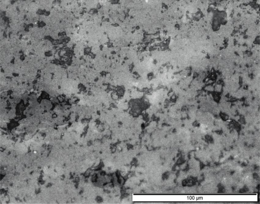
2                                                                              Advances in Materials Science and Engineering

engines from wear, erosion, pores, and other severe thermal       that within a certain limit, the thick coatings maintain better
degradations. An average temperature range of about 80°C          wear resistance as well as porosity compared to thin coat-
and hot-spot temperature of 170°C have been reduced in the        ings, which extends the product lifetime accordingly [19, 20].
turbine blades with 250 μm thickness thermal-sprayed coat-        However, thick coatings may create micropores, delami-
ing [8]. Plasma-sprayed TBCs are typically applied to increase    nation, cracks, and improper mechanical bonding [21, 22].
the resistance of heat engines against wear and corrosion at a    Likewise, larger internal stress and other aspects will make
room/high temperature. The most frequently used plasma-           the thick coating peel off from the coated surface [23]. Thus,
sprayed feedstock powders in thermal barrier application are      thick coatings are usually difficult to be applied in practice.
alumina-titania (Al2O3-TiO2) and yttria-stabilized zirconia       Wear-out failure is another main damage formed in the
(YSZ). In recent decades, alumina-titania feedstock con-          layers of the material substrate. Moreover, the microstruc-
taining 3, 13, and 40 wt% compositions of titania are com-        ture characteristics and the wear resistance layer look un-
monly used rather than plain alumina-titania powders.             even due to the granularity of ceramic powders. To
During spraying, these composites are heated up to 4,000°C        overcome these drawbacks, the coating powder is mixed
and accelerated to several hundred m/s in a chemical dynamic      with reinforcement components that withstand wear and
environment of plasma-making gases and the surrounding            corrosion. In this research, Al2O3 + 3 wt%TiO2 ceramic
atmosphere [9]. At this condition, the feedstock experiences a    powder is reinforced with CNT nanocomposite for im-
high thermal load, in addition to high mechanical load upon       proving the overall wear resistance and reducing the po-
reaching the substrate. These extreme conditions can lead to      rosity of coatings [24, 25]. The addition of carbon nanotubes
substantial variations in the chemical and microstructural        is an effective way of improving the mechanical properties
composition of coatings as compared to the feedstock              and tribological performance of ceramic coatings. Due to
powders and contribute to changes in coatings microstructure      their excellent mechanical, electrical, and chemical prop-
[10]. Additionally, alumina-titania coatings are popular due to   erties, CNTs possess high tensile strength and stiffness [26].
their sliding wear resistance owing to their excellent me-        So, CNTs applied as an additive to increase the performance
chanical properties. As wear undergoes aggressive corrosion       of a ceramic coating in high-level industries.
at higher temperatures, the coating should be prepared in             Thermal barrier coatings are frequently used in heavy-
such a manner as to withstand wear and corrosion at the same      duty, high-speed industrial applications for equipment
time. On the other hand, TBC characteristics are mainly           protection. An integral part of TBC in a metallic substrate is
affected by the pores formed in the microstructure of coatings     to prevent the formation of large pores to reduce heat
during spraying. Hence, several experiments are performed to      insulation and thermal stresses. However, accurate pre-
identify the relationship between processing methods, po-         diction of porosity is highly complex because of the
rosity, and microstructure, resulting in properties including     challenging porous structure and the ultrathin thickness of
heat conductivity, thermal shock resistance, microhardness,       the coating. In this paper, a conventional ceramic powder
fracture toughness, and so on [11, 12].                           Al2O3 + 3 wt%TiO2 along with 1%, 3%, and 5% CNT-doped
    Porosity is identified as an important feature for cor-        combination of Al2O3 + 3 wt%TiO2 ceramics was prepared
rosion and wear that influences the life span of hot com-          and fabricated on the sample steel substrate via air plasma
partments. The presence of pores in the coating is required       spraying deposition technique. The mechanical and wear
not only for thermal conductivity reduction but also for the      characteristics of the coated substrate using these powders
compensation of stress resulting from expansion because of        are studied and investigated. The main objective of this
temperature variations and heat effects [13, 14]. Neverthe-        research is to analyze the wear response and porosity of
less, in some cases, pores cause air penetration and gas          coatings prepared with conventional ceramic and carbon
combustion, which in turn create metal corrosion inside the       nanotube mixed powders. Moreover, it investigates the
parts of turbine engines [15]. Therefore, porous optimization     influence of ceramic as well as CNTs reinforced ceramic
on the top coat is significant to enhance the thermal              coatings deposited on the substrate. The microstructure
properties for the entire lifetime of the product. The study in   and tribological properties of thermal-sprayed coatings are
[16] indicated that the residual stress of coatings steadily      also systematically analysed, and the wear mechanism has
upsurges from 60 MPa compressive stress to 40 MPa tensile         been determined.
stress along with the rise of porosity from 14% to 17%. Also,
the authors of [17] investigated the impact of both thermal       2. Experimental Methodology
conductivity and porosity in coated surfaces. It is found that
increasing the porosity could block the heat transfer between     2.1. Materials. The coatings are deposited on the AISI 1020
coating layers. However, low porosity would eliminate the         steel substrate of dimension 65 × 55 × 5 mm. This is a me-
resistance towards corrosion. The study in [18] pointed out       dium-carbon steel substrate composed of 0.25–0.50% car-
that the reduction in thermal conductivity is possibly due to     bon, 0.60–1.65% manganese, 0.4% (maximal) phosphorous,
interlamellar pores occurring in the coated regions. Fur-         and 0.5% (maximal) sulphur. Carbon steels are extensively
thermore, it also occurs because of the limited character-        used for large industrial applications. Al2O3 + 3 wt%TiO2
ization of porous shape and size, total porosity, and             powder with a particle size distribution of about 18–56 μm is
distribution of pores in thermal coatings.                        taken for coating deposition. This feedstock powder is ob-
    The thickness of thermal-sprayed coatings normally            tained from Metallizing Equipment Co. Pvt. Ltd, Jodhpur,
ranges between 300 and 400 μm. Numerous studies revealed          India. In a typical thermal barrier coating system, two layers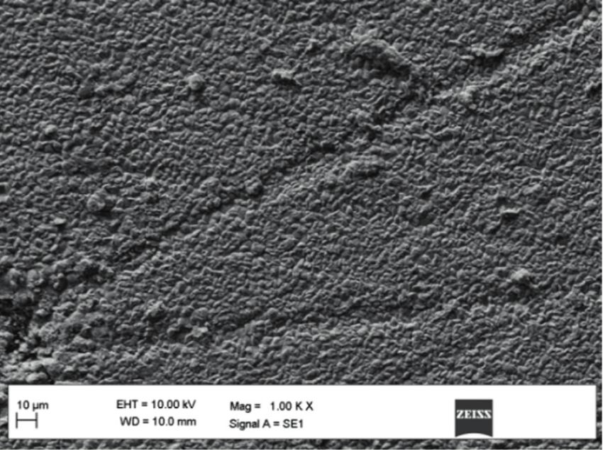
Advances in Materials Science and Engineering                                                                                 3

are applied on the surface of the substrate, namely the bond     parameters of the coating deposition influence the output
coat and the top coat. Therefore, Al2O3 + 3 wt%TiO2 ceramic      voltage and arc power per unit hydrogen gas flow rate. A
powder is taken for deposition of the top coat, and Ni-5%Al      spray angle of 90° is maintained for coating all types of
or Ni-5%Cr ceramic powders are taken as bond coat ma-            powder composition. Two auxiliary air jets are placed
terial. The substrates are coated with both conventional         parallel to the plasma flame to cool the substrate during
ceramics as well as nanocomposite incorporated ceramics.         deposition and remove the weakly bonded and unmelted
For nanocomposite incorporated powder preparation,               powder particles. The bond coat and the top coat are de-
multiwalled carbon nanotubes (MWCNTs) are obtained               posited with a thickness of about 100–150 μm and
from United Nanotech Innovations Pvt. Ltd., Bangalore,           250–350 μm, respectively.
India. The physical properties of MWCNTs include 25 μm
outer diameter, 10 microns length, >98% purity, 220 m2/g
specific surface area, and 0.14 g/cm3 bulk density. The blend     2.4. Microstructural Characterization. Cross-sectional sam-
of alumina-titania feedstock is subsequently mixed with 1%,      ples of dimension 10 × 5 × 5 mm are cut from the coated
3%, and 5% MWCNTs of approximate diameter 25 μm and              sample using a low-speed diamond saw (150 low-speed dia-
length 10 microns for 8 hours at 100 rpm speed to produce        mond saw, MTI Corporation) for examining the mechanical
the reinforced ceramic composite powder. Agglomeration of        properties and microstructural characteristics of coatings. The
powders during blending is avoided using hardened steel          surface characterization of samples is analysed using two
balls in the ball milling chamber. It has been learned that up   microscopes, namely Zeiss Supra 40 field emission scanning
to 5 wt% SiO2-MgO-coated MWCNTs were added with                  electron microscope (FE-SEM) and Zeiss scanning electron
polymer for coating purposes [27].                               microscope (SEM). Before taking SEM, the cross-sectional
                                                                 sample inserts are subjected to thermoplastic cold mount with
                                                                 Geosyn cold mounting compound powder and liquid pro-
2.2. Substrate Preparation. The AISI 1020 steel substrate is
                                                                 cured from Geologists Syndicate Private Limited, Kolkata,
cut from a steel bar of width 55 mm and thickness 5 mm
                                                                 India. The cold mounted sample inserts are then allowed for
using a power saw. A surface grinder Alex NH 500 is used to
                                                                 surface polishing with three different substances such as SiC
remove the oxide from the top and bottom surfaces of the
                                                                 abrasive paper (220, 400, 600, 800, and 1,000 grades), diamond
substrate and produce 0.1 μm roughness to the surfaces. The
                                                                 paste polishing (grade range 8, 6, 3, and 1 micron), and velvet
top surface of the substrate is grit blasted inside a suction-
                                                                 cloth fixed auto polisher (Struers, LaboPol-21).
type cabinet of the grit-blasting machine with alumina grits
of mesh size 24 at 100 psi air pressure, and a stand-off
distance of 125 mm. This will provide a surface roughness of     2.5. Porosity Measurement. Thermal-sprayed coatings are
5 μm thick, which is essential for achieving superior me-        vulnerable to porosity formation because of the improper
chanical anchorage between the substrate and the bond coat.      fusion between spray substances or gaseous expansion gen-
The oxide layers formed during the time gap between surface      erated on spraying. Therefore, porosity determination is es-
grinding and grit blasting processes are removed at the final     sential in order to observe the effects of variable spray
stage of grit blasting. The grit blasted surface is then sub-    parameters and the appropriateness of coating for its intended
jected to ultrasonic cleaning in the isopropanol bath for 10     purpose. Based on the type of application, low volume or none
minutes in order to remove the unwanted dirt particles from      of the porosity might be endurable. The porosity measurement
the surface. Before bond coat deposition, the wet substrate is   in this work is carried out as per [29] procedure.
then thermally preheated for 150–200°C using a plasma gun
with argon/nitrogen as the plasma gas. This will remove oil,
grease, water vapour, and foreign particles and present a        2.6. Wear Characterization. Wear tests have been per-
clean and nascent substrate surface for the bond coat de-        formed on as-sprayed coatings using Ducom tribometer
position. The temperature variations throughout preheating       (wear and friction monitor: TR-20-M24) under different
are monitored via a noncontact instrument called an optical      loading conditions (0.5–1.5 kgf ) with sliding velocities
pyrometer.                                                       (0.17–0.5 m/s) for a constant sliding distance of 300 m.
                                                                 Tungsten carbide balls of 6 mm diameter are used as the
2.3. Plasma Spraying. The conventional ceramic powder of         counter bodies for all tests. The weight loss in the coatings
Al2O3 + 3 wt%TiO2 and its corresponding CNT-doped                after the wear test is assessed by comparing the weight of
mixtures are deposited as the top coat on the steel substrate    samples before and after the wear test with an electronic
using the plasma spraying technique. The schematic diagram       balance (Mettler Toledo Classic Plus, AB265-s/Fact). The
of plasma-sprayed coating is depicted in Figure 1. Before the    debris formed on the samples during the wear test is
top coat deposition, the substrate is coated with an inter-      manually removed by blowing air while measuring the
mediate adhesion layer called a bond coat. Ni-5%Al or Ni-        sample weight after the wear test. The wear test is con-
5%Cr composites are applied as the bond coat onto the            ducted three times for each load and speed condition to
substrate material. The coatings are deposited onto the          confirm the consistency of results. Furthermore, average
substrate using a Sulzer Metco 3MB plasma gun fixed on a          weight loss and standard deviation are calculated. It is to be
CNC X-Y table. The plasma gun uses argon and hydrogen as         noted that the wear tests are performed in compliance with
the primary and secondary gases, respectively. The process       ASTM G99-05 standards.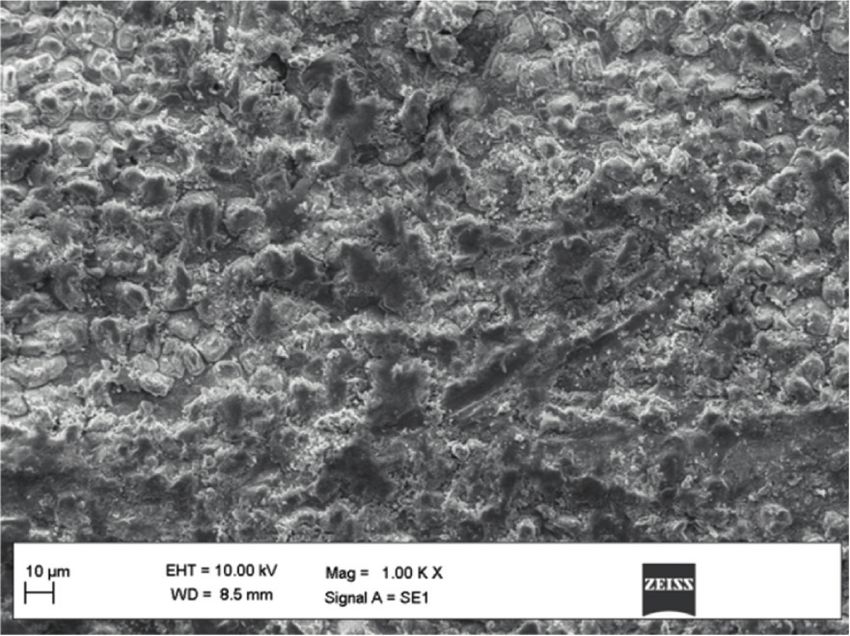
4 Advances in Materials Science and Engineering
PLASMA SPRAY PROCESS Powder Spray Film
Powder
Plasma Jet
Substrate
Arc
Molten Particle Splat
Anode
Cathode
Water Ar,H2 Water
Figure 1: Schematic diagram of plasma spraying technique [28].
3. Results and Discussion coatings obtained after the addition of CNTs in 1 wt%, 3 wt
%, and 5 wt%, respectively. It is observed from Figures 5(a)–
3.1. Coating Thickness. The cross-sectional micrographs of 5(d) that micropores are present in the coating micro-
CNTs reinforced Al2O3 + 3 wt%TiO2 coatings showing structure with different sizes. The size of the pores and the
coatings thickness are shown in Figure 2. It can be seen from number of pores per square millimeter were analysed using
Figure 2 that the coating thickness of the top coat and bond MetImage LX software and shown in Figures 5 and 6. It was
coat are quite different. The average thickness of the top coat found that the addition of CNTs reduced the porosity level in
is varying in the range of 474–505 μm (Figures 2(a)–2(c)), the coatings, and this is due to the fact that CNTs are oc-
and the bond coat is obtained with a thickness ranging from cupying the micropores and resulting in the reduction of the
42 to 49 μm. It can also be observed that the adhesion be- overall porosity percentage.
tween the coatings and the substrate is very good, and no The variation in porosity in all the coatings is shown in
cracks were noticed. The EDX analysis of Al2O3 + 3 wt% Figure 6. The presence of micropores in size ranges
TiO2 + 5% CNTs reinforced coating is shown in Figure 3, and (0–10 μm) occurred more on all coated samples, and
the presence of Ti, C, Al, and so on can be seen in the coating gradually, pore volume decreased with an increase in pores
microstructure. Also, the white flakes in the microstructure size. It can be observed that the 1% CNTs reinforced coating
represent alpha-alumina whereas the sharp edge portions exhibited fewer pores formation than the other coatings,
represent titania (Figure 3). whereas the 3% CNTs reinforced coatings have more pores
per square millimeter (see Figure 6). Furthermore, in 5%
CNTs reinforced coatings, the number of pores per square
3.2. Phase Analysis. The X-ray diffraction (XRD) patterns for millimeter have been decreased. The coating microstructures
Al2O3 + 3 wt%TiO2 composite coatings obtained with and and MetImage analyzer results indicate that 1% CNTs re-
without CNTs reinforcement are shown in Figure 4, and the inforcement is sufficient for a homogeneous distribution in
presence of Al2O3 and TiO2 phases and CNTs can be seen Al2O3 + 3 wt%TiO2 coating, and this can reduce the for-
clearly. Through EDX and XRD analysis, the presence of mation of pores in the coating microstructure effectively.
these phases in the coating microstructure has been con- The nonuniform melting and distribution of CNTs in the
firmed. It is to be noted that the alpha-alumina present in the coating increase the percentage porosity in the coatings. The
coating resists high-temperature intrusion, and the titania is agglomerates of CNTs in the coating may cause nonuniform
present in the form of rutile titania. It can be observed that CNTs melting and thus resulting in a higher percentage of
the intensity of peaks in the XRD pattern representing TiO2 porosity. It has been observed in previous works also that
and CNTs is very small as their percentage composition is just the nominal addition of CNTs has supported the alu-
very less. It can also be seen that the presence of CNTs mina to retain the liquid state for a long time and develop the
cannot be seen in the 1% CNTs reinforced coatings due to good distribution of alumina in CNTs reinforced alumina-
the smaller volume proportion. It can be observed from the titania composite coatings [30]. It can also be observed that
intensity of the phases that the phase distribution is similar the higher coating thickness has resulted in a higher number
in all four types of coatings with slight variation in their of pores formed in the coating microstructure.
quantity.
3.4. Wear Characteristics. The wear tests are conducted at
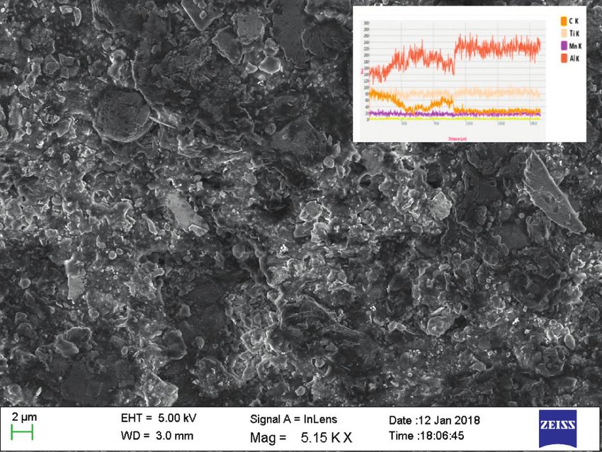
3.3. Porosity Measurement. Figure 5(a) shows the micro- three different load and speed conditions with a constant
structure of Al2O3 + 3 wt%TiO2 coating without adding sliding distance of 300 m using a steel ball at room tem-
CNTs, and Figures 5(b)–5(d) show the microstructure of perature. The wear characteristics of the coatings are shown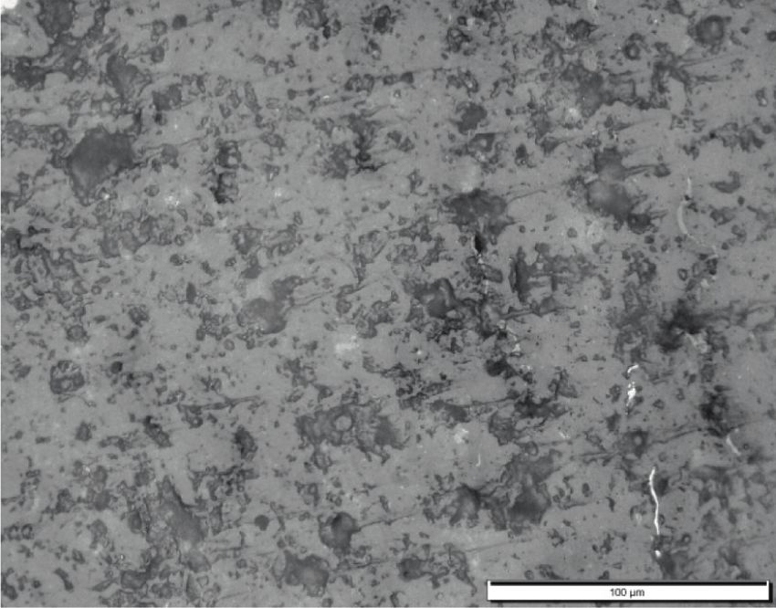
Advances in Materials Science and Engineering                                                                                     5

                                (a)                                                             (b)

                                                                (c)

Figure 2: SEM micrograph of cross section showing coating thickness of (a) Al2O3 + 3 wt%TiO2 + 1%CNTs reinforced coating, (b)
Al2O3 + 3 wt%TiO2 + 3%CNTs reinforced coating, and (c) Al2O3 + 3 wt%TiO2 + 5%CNTs reinforced coating.

                                                                                   Titania
                                                Alpha-alumina

           Figure 3: SEM micrograph of Al2O3 + 3 wt%TiO2 + 5% CNTs reinforced composite coating surface with EDX.

in Figure 7. At 0.17 m/s sliding speed, it can be observed            3.6 mg (Figure 7(a)), whereas for CNTs reinforced coatings,
that the weight loss of alumina-titania composite coating             the weight loss is changing from 2.5 to 3.4 mg. It can also be
without CNTs reinforcement is ranging in between 3.1 and              seen that in all the coatings, the weight loss is gradually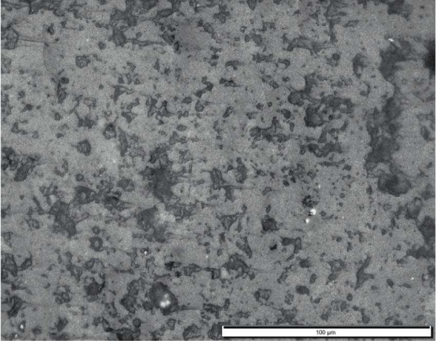
6                                                                                                          Advances in Materials Science and Engineering

                                                                                      α
                                                                           α
                                                                                                           α
                                                                                 α                α                     α
                                                                                                                   α
                                                      d
                                                              β Ф

                                      Intensity
                                                                           α                  α                α       α
                                                                                          α
                                                                                 α                                 α
                                                      c
                                                              β Ф

                                                                                          α
                                                                           α     α            α            α
                                                                                                                   α α
                                                      b
                                                                   Ф

                                                                           α    α    α                     α
                                                                                              α                         α
                                                     a                                                                 α
                                                                   Ф

                                                              20                 40                   60                    80
                                                                               2theta (deg)

                                                  β - CNT
                                                  α - A12O3
                                                  Ф - TiO2

Figure 4: XRD pattern of (a) Al2O3 + 3 wt%TiO2 coating without CNTs reinforcement, (b) Al2O3 + 3 wt%TiO2 + 1% CNTs reinforced
coating, (c) Al2O3 + 3 wt%TiO2 + 3% CNTs reinforced coating, and (d) Al2O3 + 3 wt%TiO2 + 5% CNTs reinforced coating.

                                                                                                                       Porosity
                         Porosity

                                    (a)                                                                                      (b)
                                                                       Figure 5: Continued.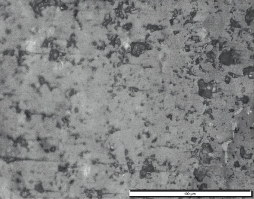
Advances in Materials Science and Engineering                                                                                                 7

                                                         Porosity

                                                                                                   Porosity

                                  (c)                                                                          (d)

Figure 5: Optical micrographs of (a) Al2O3 + 3 wt%TiO2 composite coating without CNTs reinforcement, (b) Al2O3 + 3 wt%TiO2 + 1%
CNTs reinforced coating, (c) Al2O3 + 3 wt%TiO2 + 3% CNTs reinforced coating, and (d) Al2O3 + 3 wt%TiO2 + 5% CNTs reinforced coating.

                                                  1600
                                                  1400
                                                  1200
                                                  1000
                                    Pores/sq mm

                                                   800
                                                   600
                                                   400
                                                   200
                                                     0
                                                         0-10       11:-25      26-75     76-125   126-above
                                                                        Porosity Range (µm)

                                                         0% CNT                   3% CNT
                                                         1% CNT                   5% CNT
              Figure 6: Porosity variation in alumina-titania coatings obtained with and without CNTs reinforcement.

increased with the increase of load except a small decrease                    weight loss is more, and it is in the range of 2.8–3.9 mg.
at 1 kgf load in the case of coatings obtained without CNTs                    Furthermore, there is a short drop in the weight loss at
reinforcement.                                                                 1 kg load in the case of 3% CNTs reinforced coatings
    The wear characteristics obtained at 0.33 m/s sliding                      (Figure 8).
speed are shown in Figure 7(b). At this sliding speed also                         However, it can be clearly seen that the weight loss is
the trend of the variation in weight loss with respect to the                  increased with the increase in load and sliding velocity. Also,
load is almost similar. For coatings obtained without                          it can be observed that 1 wt% CNTs reinforced coatings
CNTs reinforcement, the weight loss is changing from 3.5                       exhibited good adhesion of coating with the substrate and
to 4.2 mg, whereas for the coatings with CNTs rein-                            resulted in lesser weight loss and thereby higher wear re-
forcement, the weight loss is in the range of 2.6–4.3 mg. It                   sistance. The factors such as hardness, porosity, and fracture
can also be observed that there is a short decrease in                         strength might play a significant role in the wear resistance
weight loss at 1 kgf load in the case of 3% CNTs reinforced                    of coatings. It can also be seen that the weight loss in the case
coatings (Figure 7(b)). Figure 7(c) shows the wear                             of 3 wt% CNTs reinforced coatings and coatings without
characteristics of coatings at 0.5 m/s sliding speed. At this                  CNTs reinforcement is almost nearer at all load and speed
highest speed, weight loss is in the range of 3.8–4.2 mg for                   conditions. Lastly, it can be observed that the weight loss is
the coatings obtained without CNTs reinforcement, and it                       more in the coatings without CNTs reinforcement, and the
shows that wear rate is very much higher at the highest                        weight loss is minimum in the case of 1% CNTs reinforced
sliding speed. For CNTs reinforced coatings also, the                          coatings at all the conditions.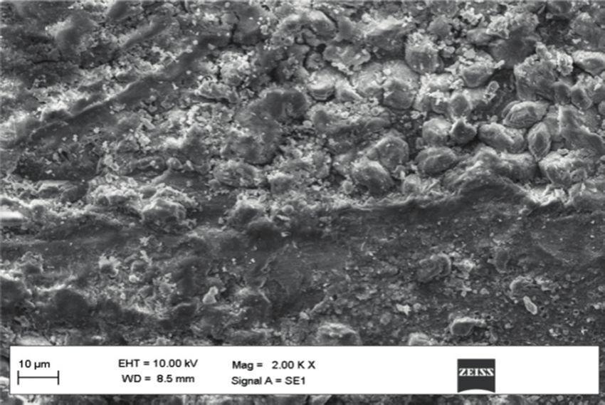
8                                                                                                                                       Advances in Materials Science and Engineering

                                                                                                                        0.0036
                    0.0038

                                                                                                                        0.0034
                    0.0036

                    0.0034                                                                                              0.0032
    Mass Loss (g)

                                                                                                        Mass Loss (g)
                    0.0032                                                                                              0.0030

                    0.0030                                                                                              0.0028

                    0.0028                                                                                              0.0026

                    0.0026                                                                                              0.0024

                    0.0024
                                                                                                                        0.0022
                             0.4     0.6     0.8        1.0                    1.2      1.4     1.6
                                                                                                                                 0.4      0.6     0.8        1.0       1.2   1.4   1.6
                                                     Load (kgf)
                                                                                                                                                          Load (kgf)
                                   Speed @ 955 rpm
                                                                                                                                        Speed @ 955 rpm
                                   Speed @ 637 rpm
                                                                                                                                        Speed @ 637 rpm
                                   Speed @ 319 rpm
                                                                                                                                        Speed @ 319 rpm
                                                   (a)                                                                                                   (b)
                                                                     0.0042

                                                                     0.0040

                                                                     0.0038

                                                                     0.0036
                                                     Mass Loss (g)

                                                                     0.0034

                                                                     0.0032

                                                                     0.0030

                                                                     0.0028

                                                                     0.0026

                                                                     0.0024
                                                                              0.4      0.6     0.8        1.0                     1.2      1.4     1.6
                                                                                                       Load (kgf)

                                                                                     Speed @ 955 rpm
                                                                                     Speed @ 637 rpm
                                                                                     Speed @ 319 rpm
                                                                                                      (c)

Figure 7: Mass loss measured during the experimentation with Al2O3 + TiO2 coating for different rotational speeds: (a) Al2O3 + TiO2 + 1%
CNT, (b) Al2O3 + TiO2 + 3% CNT, and (c) Al2O3 + TiO2 + 5% CNT.

    The wear resistance is directly proportional to the                                                       mm3 is recorded for 3% of CNT in Al2O3 + TiO2. Wear re-
hardness of the sliding surface. For a rotating ball, the                                                     sistance is also influenced by the process condition such as
hardness is 85 HRC, and for the Al2O3 + TiO2, it is 65 HRC.                                                   applied load and sliding velocity or speed.
Both the materials are rich in hardness compared to the
substrate material. During sliding experimentation, in addi-
tion to the influence of surface hardness, the frictional energy                                               3.5. Wear Mechanism. Figure 9 shows the SEM micrographs
generated will highly influence to cause wear. In this research,                                               of wear track obtained on the worn-out surface of
the reinforcement of CNT in the the Al2O3 + TiO2 has si-                                                      Al2O3 + 3 wt%TiO2 coatings reinforced with different per-
multaneously increased, but in 5%, CNT reinforcement is                                                       centage proportions of CNTs. Microcracks and fragments of
maintaining the medium value of surface hardness because of                                                   coating are observed on the wear track surface (Figures 9(a)
more ceramic in the specimen. The behavior of CNT in                                                          and 9(c)), and more fragments of coating material that came
Al2O3 + TiO2 reveals the performance of diamond during                                                        out and fallen on the nearby coating can be seen in
sliding analysis. The maximum wear resistance of 5,800 Nm/                                                    Figure 9(b). Also, the deep scratch can be noticed, and no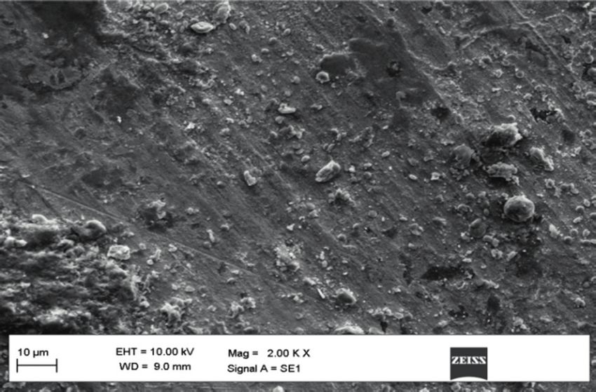
Advances in Materials Science and Engineering 9
5200 6000
5600
4800
5200
Wear resistance (Nm/mm3)
Wear resistance (Nm/mm3)
4400
4800
4000
4400
3600 4000
3200 3600
2800 3200
2400 2800
2400
2000
2000
0.4 0.6 0.8 1.0 1.2 1.4 1.6
0.4 0.6 0.8 1.0 1.2 1.4 1.6
Load (kgf)
Load (kgf)
Speed @ 955 rpm
Speed @ 955 rpm
Speed @ 637 rpm
Speed @ 637 rpm
Speed @ 319 rpm
Speed @ 319 rpm
(a) (b)
4800
4400
Wear resistance (Nm/mm3)
4000
3600
3200
2800
2400
2000
1600
0.4 0.6 0.8 1.0 1.2 1.4 1.6
Load (kgf)
Speed @ 955 rpm
Speed @ 637 rpm
Speed @ 319 rpm
(c)
Figure 8: Calculated wear resistance for the test experiments on Al2O3 + TiO2 coatings for different rotational speeds: (a) Al2O3 + TiO2 + 1%
CNT, (b) Al2O3 + TiO2 + 3% CNT, and (c) Al2O3 + TiO2 + 5% CNT.
cracks are observed (Figure 9(b)). The higher fragmentation formed in the coating also can be seen (Figure 10(b)). The
of coating and crack formation can be attributed to the poor uniform mixing of CNT particles melted partially in the
adhesion strength and low ductility of the coating. However, coating could improve the wear resistance of coatings. The
the higher coating thickness and lower percentage porosity wetting of the CNTs might be one reason for the good
reduced the wear loss of these coatings. However, the 3 wt% dispersion observed. Therefore, the nanotubes that are
CNT addition has reduced the formation of microcracks and dispersed in the slurry appear relatively uniformly distrib-
also the fragmentation of coating, and this can be attributed uted over the Al2O3 + 3 wt%TiO2 particle surface. The 1 wt%
to the formation of CNTs bridges in the coating micro- CNTs reinforced Al2O3 + 3 wt%TiO2 coatings are showing
structure. Similar types of coating fragments were also the lower porosity minimizing the defects in the worn
noticed on the worn surface by [31]. surface as shown in Figure 10(a). It can also be observed that
The SEM micrograph of wear track morphology on the the wear track width has been increased at a higher load. The
worn-out coating surface is shown in Figure 10. It can be wear debris is seen clearly in the 3% reinforced coatings
observed that there are many microcracks on the worn (Figure 10(b)), and the cavities formed in the worn surface
surface due to cyclic stresses during the wear tests. The debris are due to the pull-out of coating material. In 5 wt% CNTs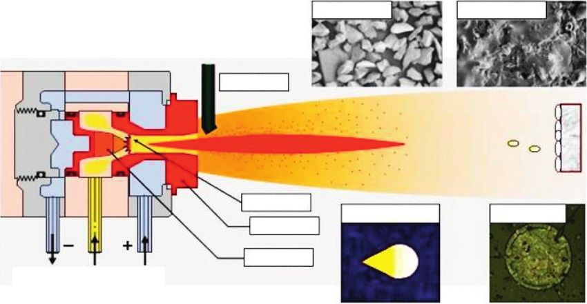
10                                                                                Advances in Materials Science and Engineering

                                           Wear track

                                                                                             Coating Fragments

                                   (a)                                                        (b)

                                                                 (c)

Figure 9: SEM micrograph of wear track morphology on the worn-out surface obtained at 0.5 m/s sliding speed and 1 kgf normal load for
(a) Al2O3 + 3 wt%TiO2 + 1 wt% CNTs reinforced coating, (b) Al2O3 + 3 wt%TiO2 + 3 wt% CNTs reinforced coating, and (c) Al2O3 + 3 wt%
TiO2 + 5 wt% CNTs reinforced coating.

                                                                                                          Debris

              Cracks
                                                                                                      Cavities

                                 (a)                                                            (b)
                                                        Figure 10: Continued.
Advances in Materials Science and Engineering 11
Cracks
(c)
Figure 10: SEM micrograph of wear track morphology on the worn-out surface obtained at 0.17 m/s sliding speed and 1.5 kgf normal load
for (a) Al2O3 + 3 wt%TiO2 + 1 wt% CNT reinforced coating, (b) Al2O3 + 3 wt%TiO2 + 3 wt% CNT reinforced coating, and (c) Al2O3 + 3 wt%
TiO2 + 5wt% CNT reinforced coating.
reinforced coatings, the cracks can be observed on the worn- (6) However, it can be clearly seen that the addition of
out surface because of higher load and lesser sliding speed, CNTs to the alumina-titania coatings will improve
which resulted in more cyclic stresses in the coating material their wear resistance and make them suitable for
(Figure 10(c)). critical tribological applications.
4. Concluding Remarks Data Availability
In this work, the characteristics of the plasma-sprayed No data were used to support this study.
coatings obtained with and without CNTs reinforcement are
evaluated and compared. Particularly, the percentage po- Conflicts of Interest
rosity and tribological characteristics of the coatings have
been investigated thoroughly. The following conclusions can The authors declare that they have no conflicts of interest.
be drawn from this investigation:
(1) In all the coatings investigated, the micropores are References
present in their microstructure, and the percentage [1] J. Lei, C. Shi, S. Zhou, Z. Gu, and L.-C. Zhang, “Enhanced
porosity is decreased with the increase of the per- corrosion and wear resistance properties of carbon fiber
centage of CNTs. This is due to the metallurgical reinforced Ni-based composite coating by laser cladding,”
fusion and surface reaction of CNT with Surface and Coatings Technology, vol. 334, pp. 274–285, 2018.
Al2O3 + TiO2. As a result, the metallurgical reaction [2] F. Wang, F. Zhang, L. Zheng, and H. Zhang, “Structure and
between the elements has simultaneously increased corrosion properties of Cr coating deposited on aerospace
the surface hardness. bearing steel,” Applied Surface Science, vol. 423, pp. 695–703,
2017b.
(2) The presence of micropores in 1% and 5% CNTs [3] A. Lekatou, D. Sioulas, A. E. Karantzalis, and D. Grimanelis,
reinforced Al2O3 + 3 wt%TiO2 coatings is minimum, “A comparative study on the microstructure and surface
and it has been noticed that the homogeneous dis- property evaluation of coatings produced from nano-
tribution of CNTs and formation of CNTs bridges in structured and conventional WC-Co powders HVOF-sprayed
these coatings have reduced the percentage porosity. on Al7075,” Surface and Coatings Technology, vol. 276,
(3) It is also found that the weight loss in the coatings is pp. 539–556, 2015.
[4] D. Wang, B. Zhang, C. Jia et al., “Influence of carbide grain
more at higher loads and higher sliding speeds due to
size and crystal characteristics on the microstructure and
more cyclic stresses induced in the coating during mechanical properties of HVOF-sprayed WC-CoCr coat-
the wear tests. ings,” International Journal of Refractory Metals and Hard
(4) It is observed that the weight loss is gradually re- Materials, vol. 69, pp. 138–152, 2017a.
duced with the increase of CNTs reinforcement [5] F. Kern, P. Palmero, F. G. Marro, and A. Mestra, “Processing
between 1 and 5 wt%. of alumina-zirconia composites by surface modification route
with enhanced hardness and wear resistance,” Ceramics In-
(5) The good adhesion of coating that resulted in lesser ternational, vol. 41, no. 1, pp. 889–898, 2015.
weight loss has been observed in the case of 1% CNTs [6] J. Mehta, V. K. Mittal, and P. Gupta, “Role of thermal spray
reinforced alumina-titania coatings, whereas in other coatings on wear, erosion and corrosion behavior: a review,”
coatings, very poor adhesion resulting in the for- Journal of Applied Science and Engineering, vol. 20, no. 4,
mation of cracks has been observed. pp. 445–452, 2017.12 Advances in Materials Science and Engineering
[7] M. A. Zavareh, A. A. D. M. Sarhan, B. B. A. Razak, and process,” Surface and Coatings Technology, vol. 205, no. 4,
W. J. Basirun, “Plasma thermal spray of ceramic oxide coating pp. 1039–1046, 2010.
on carbon steel with enhanced wear and corrosion resistance [22] N. Serres, F. Hlawka, S. Costil, C. Langlade, and F. Machi, “An
for oil and gas applications,” Ceramics International, vol. 40, investigation of the mechanical properties and wear resistance
no. 9, pp. 14267–14277, 2014. of NiCrBSi coatings carried out by in situ laser remelting,”
[8] M. Peters, C. Leyens, U. Schulz, and W. A. Kaysser, “EB-PVD Wear, vol. 270, no. 9-10, pp. 640–649, 2011.
thermal barrier coatings for aeroengines and gas turbines,” [23] S. Sivaprakasam, M. O. Sikder, L. Ramalingam, G. Kaur,
Advanced Engineering Materials, vol. 3, no. 4, pp. 193–204, J. M. Dufour, and N. Moustaid-Moussa, “SLC6A14 deficiency
2001. is linked to obesity, fatty liver, and metabolic syndrome but
[9] G. Mauer, R. Vaßen, and D. Stöver, “Detection of melting only under conditions of a high-fat diet,” Biochimica et
temperatures and sources of errors using two-color pyrometry Biophysica Acta (BBA)-Molecular Basis of Disease, vol. 1867,
during in-flight measurements of atmospheric plasma- no. 5, Article ID 166087, 2021.
sprayed particles,” International Journal of Thermophysics, [24] G. M. T. Basha, A. Srikanth, and B. Venkateshwarlu, “Effect of
vol. 29, no. 2, pp. 764–786, 2008. reinforcement of carbon nanotubes on air plasma sprayed
[10] A. Richter, L. M. Berger, Y. J. Sohn, S. Conze, K. Sempf, and conventional Al2O3-3% TiO2 ceramic coatings,” Materials
R. Vaßen, “Impact of Al2O3-40 wt.% TiO2 feedstock powder Today: Proceedings, vol. 20, pp. 191–194, 2020.
[25] F. Huang, H. Xu, W. Liu, and S. Zheng, “Microscopic
characteristics on the sprayability, microstructure and me-
characteristics and properties of titaniferous compound
chanical properties of plasma sprayed coatings,” Journal of the
reinforced nickel-based wear-resisting layer via in situ pre-
European Ceramic Society, vol. 39, no. 16, pp. 5391–5402, 2019.
cipitation of plasma spray welding,” Ceramics International,
[11] P. Carpio, Q. Blochet, B. Pateyron et al., “Correlation of
vol. 44, no. 6, pp. 7088–7097, 2018.
thermal conductivity of suspension plasma sprayed yttria
[26] M. A. Samad and S. K. Sinha, “Mechanical, thermal and
stabilized zirconia coatings with some microstructural ef-
tribological characterization of a UHMWPE film reinforced
fects,” Materials Letters, vol. 107, pp. 370–373, 2013. with carbon nanotubes coated on steel,” Tribology Interna-
[12] S. Tailor, M. Singh, R. M. Mohanty, and A. V. Doub, “Mi- tional, vol. 44, no. 12, pp. 1932–1941, 2011.
crostructural and thermal properties of plasma sprayed YSZ [27] K. Nemeth, N. Varro, B. Reti et al., “Synthesis and investi-
nano-clusters thermal barrier coatings,” Journal of Cluster gation of SiO2-MgO coated MWCNTs and their potential
Science, vol. 27, no. 5, pp. 1501–1518, 2016. application,” Scientific Reports, vol. 9, no. 1, pp. 15113–15211,
[13] N. Curry, N. Markocsan, X. H. Li, A. Tricoire, and 2019.
M. Dorfman, “Next generation thermal barrier coatings for [28] Y. Zhang, T. T. Zuo, Z. Tang et al., “Microstructures and
the gas turbine industry,” Journal of Thermal Spray Tech- properties of high-entropy alloys,” Progress in Materials
nology, vol. 20, no. 1-2, pp. 108–115, 2011. Science, vol. 61, pp. 1–93, 2014.
[14] N. Curry, N. Markocsan, L. Östergren, X.-H. Li, and [29] E2109-01, Standard Test Methods for Determining Area Per-
M. Dorfman, “Evaluation of the lifetime and thermal con- centage Porosity in Thermal Sprayed Coatings, ASTM Inter-
ductivity of dysprosia-stabilized thermal barrier coating national, West Conshohocken, PA, USA, 2014.
systems,” Journal of Thermal Spray Technology, vol. 22, no. 6, [30] J. G. Thakare, R. S. Mulik, and M. M. Mahapatra, “Effect of
pp. 864–872, 2013. carbon nanotubes and aluminum oxide on the properties of a
[15] F. Cernuschi, “Can TBC porosity be estimated by non-de- plasma sprayed thermal barrier coating,” Ceramics Interna-
structive infrared techniques? a theoretical and experimental tional, vol. 44, no. 1, pp. 438–451, 2018.
analysis,” Surface and Coatings Technology, vol. 272, [31] K. Yang, J. Li, Q. Wang, Z. Li, Y. Jiang, and Y. Bao, “Effect of
pp. 387–394, 2015. laser remelting on microstructure and wear resistance of
[16] A. Portinha, V. Teixeira, J. Carneiro et al., “Residual stresses plasma sprayed Al2O3-40% TiO2 coating,” Wear, vol. 426,
and elastic modulus of thermal barrier coatings graded in pp. 314–318, 2019.
porosity,” Surface and Coatings Technology, vol. 188-189,
pp. 120–128, 2004.
[17] A. Kulkarni, A. Goland, H. Herman et al., “Advanced neutron
and X-ray techniques for insights into the microstructure of
EB-PVD thermal barrier coatings,” Materials Science and
Engineering, vol. 426, no. 1-2, pp. 43–52, 2006.
[18] W. Chi, S. Sampath, and H. Wang, “Microstructure-thermal
conductivity relationships for plasma-sprayed yttria-stabi-
lized zirconia coatings,” Journal of the American Ceramic
Society, vol. 91, no. 8, pp. 2636–2645, 2008.
[19] Z. Piao, B. Xu, H. Wang, and C. Pu, “Effects of thickness and
elastic modulus on stress condition of fatigue-resistant
coating under rolling contact,” Journal of Central South
University of Technology, vol. 17, no. 5, pp. 899–905, 2010.
[20] Z. H. Wen, Y. Bai, J. F. Yang, and J. Huang, “Effect of vacuum
re-melting on the solid particles erosion behavior of Ni60-
NiCrMoY composite coatings prepared by plasma spraying,”
Vacuum, vol. 134, pp. 73–82, 2016.
[21] N. Serres, F. Hlawka, S. Costil, C. Langlade, and F. Machi,
“Microstructures and environmental assessment of metallic
NiCrBSi coatings manufactured via hybrid plasma sprayYou can also read