Image-based Orientation Determination of Mobile Sensor Platforms
←
→
Page content transcription
If your browser does not render page correctly, please read the page content below

The International Archives of the Photogrammetry, Remote Sensing and Spatial Information Sciences, Volume XLIII-B1-2021
                                                XXIV ISPRS Congress (2021 edition)

                  Image-based Orientation Determination of Mobile Sensor Platforms

                                                        O. Hasler *, S. Nebiker

          Institute of Geomatics Engineering, FHNW University of Applied Sciences and Arts Northwestern Switzerland,
                                 Muttenz, Switzerland – (oliver.hasler, stephan.nebiker)@fhnw.ch

KEY WORDS: Orientation estimation, image-based, panorama images, robotics, mobile sensor platforms

ABSTRACT:

Estimating the pose of a mobile robotic platform is a challenging task, especially when the pose needs to be estimated in a global or
local reference frame and when the estimation has to be performed while the platform is moving. While the position of a platform
can be measured directly via modern tachymetry or with the help of a global positioning service GNSS, the absolute platform
orientation is harder to derive. Most often, only the relative orientation is estimated with the help of a sensor mounted on the robotic
platform such as an IMU, with one or multiple cameras, with a laser scanner or with a combination of any of those. Then, a sensor
fusion of the relative orientation and the absolute position is performed. In this work, an additional approach is presented: first, an
image-based relative pose estimation with frames from a panoramic camera using a state-of-the-art visual odometry implementation
is performed. Secondly, the position of the platform in a reference system is estimated using motorized tachymetry. Lastly, the
absolute orientation is calculated using a visual marker, which is placed in the space, where the robotic platform is moving. The
marker can be detected in the camera frame and since the position of this marker is known in the reference system, the absolute pose
can be estimated. To improve the absolute pose estimation, a sensor fusion is conducted. Results with a Lego model train as a mobile
platform show, that the trajectory of the absolute pose calculated independently with four different markers have a deviation < 0.66
degrees 50% of the time and that the average difference is < 1.17 degrees. The implementation is based on the popular Robotic
Operating System ROS.

                    1. INTRODUCTION                                   features and is sensitive to outliers and illumination change. On
                                                                      the other hand, appearance-based methods directly compare
The precise estimation of position and orientation of robots or       pixel intensities of the overall image. This approach is also
autonomous vehicles is becoming increasingly important. The           referred to as dense, direct or global, depending on the context
challenge is the highly precise estimation of these values in a       (Irani and Anandan, 2000).
kinematic system. Position can be determined in near real-time
using various approaches such as motorized tachymeters
indoors and outdoors or GNSS outdoors. However, determining
the exact orientation or orientation of these platforms is
challenging. Conventional Visual SLAM/Visual Odometry
approaches can determine position and orientation, but only
relative to their initial position. In an unpublished research
project of the Institute of Geomatics (IGEO) at the FHNW, the
orientation of a platform is calculated with high accuracy using
a motion capture system carried on board the mobile platform.
However, the setup of this system is complex and scalable only
to a limited extent.

In this work, an alternative image-based approach to determine
the orientation in three Degrees of Freedom (DoF) using
panoramic cameras was developed. Panoramic cameras have the
advantage of capturing the entire environment of a platform and
provide a more geometrically robust orientation determination
                                                                      Figure 1. Mobile sensor platform with panoramic camera Ricoh
than classical cameras. In addition, this work developed and
                                                                      Theta Z1 and 360° prism mounted on a LEGO model train
investigated methods to determine the absolute orientation of a
mobile sensor platform with respect to a reference frame.
                                                                      Another criterion for distinguishing image-based orientation
                                                                      estimation is the estimated degrees of freedom (DoF). Visual
                    2. RELATED WORK                                   compass methods limit themselves to a single axis (yaw). In the
                                                                      Visual Compass approach of Morbidi and Caron (2017), only
Image-based orientation estimation is a widely researched topic       the horizontal direction change is determined from the phase
and several differentiations between its methods can be made.         correlation of two consecutive images. Visual gyroscopes
Feature-based methods try to extract image features (such as          estimate the attitude (roll, pitch and yaw angles). The two
parallel lines, vanishing points or SIFT Features) and track these    approaches of Hartmann et al. (2015) are either real-time
features over different frames. This method needs additional          capable but too inaccurate or not real-time capable. Caron and
image processing steps while extracting and tracking these            Morbidi (2018) extended their Visual Compass approach to

                                                This contribution has been peer-reviewed.
                 https://doi.org/10.5194/isprs-archives-XLIII-B1-2021-215-2021 | © Author(s) 2021. CC BY 4.0 License.               215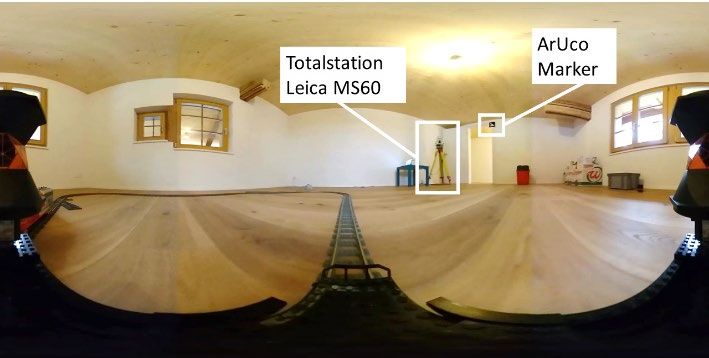
The International Archives of the Photogrammetry, Remote Sensing and Spatial Information Sciences, Volume XLIII-B1-2021
                                                XXIV ISPRS Congress (2021 edition)

Visual Gyroscope, but with a computation time of 1 second per           4. IMAGE-BASED ORIENTATION ESTIMATION
image this approach is also not operational for our application.
Finally, Visual Odometry approaches are used to determine the        Orientation determination can be divided into three parts:
camera pose (orientation and position). The indirect approach of     Relative orientation estimation, position determination and
Mur-Artal and Tardos (2017) is state-of-the-art, but panoramic       absolute orientation estimation (Figure 3). The relative
cameras cannot be used. Sumikura et al. (2019) have extended         orientation takes place in the local coordinate system odom
this approach so that 360° cameras can also be used. However,        frame, the position determination and the absolute orientation
all approaches work in a relative coordinate system or can re-       estimation in the global system map frame. Finally, a sensor
locate in an already acquired map.                                   fusion is applied to obtain an absolute pose in the map frame.

Image-based absolute orientation determination of a mobile
platform is an area that has not been extensively explored.
Approaches from Visual Localization, in which an image is
oriented with respect to reference images, are described in
Sattler et al. (2018). However, this requires a reference model
consisting of already oriented images. Another possibility
would be to calculate the orientation from the trajectory of an
absolute positioning method (e.g. tachymetry). However, only
the azimuth and the inclination in the direction of travel can be
determined, not the lateral inclination.                             Figure 3. Concept of the three parts of the absolute orientation
                                                                     estimation: relative orientation (left), position (centre) and
        3. MOBILE PLATFORM AND TEST SITE                             absolute orientation (right) with the respective reference frames

This work aims at image-based orientation determination for a        4.1 Relative Orientation Estimation
variety of mobile platforms: mobile robots or the tip of a robotic
arm, vehicle monitoring or mobile measurement platforms. For         The relative orientation calculation is performed using
feasibility reasons (including lab accessibility restrictions        OpenVSLAM (Sumikura et al., 2019). OpenVSLAM was
caused by the Covid19 pandemic), a highly dynamic Lego train         successfully implemented in the program flow and optimized
was used as a mobile sensor platform for this work at the home       for real-time computation. OpenVSLAM is ideally suited
office. This platform has the advantage of ensuring repeatability    because this implementation supports different camera systems
of manoeuvres. In addition, the sensors can be fixed and easily      (monocular, stereo, RGBD) and different camera models
arranged. A Ricoh Theta Z1 panoramic camera and a 360°               (perspective, fisheye, dual fisheye, catadioptric) with different
prism are mounted on the platform (Figure 1). A Leica MS60           imaging models (including equirectangular). In addition,
totalstation and a coded ArUco (Garrido-Jurado et al., 2014)         OpenVSLAM already provides a ROS implementation that
marker with a size of 19 x 19 cm are installed in the room           computes the relative orientation from a ROS camera stream.
(Figure 2).                                                          The trajectory with the orientations refers to the odom frame
                                                                     coordinate system with the coordinate origin at the initialization
                                                                     location.

                                                                     4.2 Position Determination

                                                                     The position of the mobile platform is continuously determined
                                                                     using a Leica MS60 multistation. For this purpose, an ROS
                                                                     node with time synchronization was developed at the Institute
                                                                     of Geomatics, which can control the MS60 and receive
                                                                     measured values. The multistation is stationed in space with
                                                                     respect to a defined coordinate system (map frame).
                                                                     Subsequently, the multistation continuously tracks the 360°
                                                                     prism, which is mounted on the mobile platform. The
Figure 2. Equirectangular camera image depicting totalstation        measurement rate is about 19 Hz and the expected 3D accuracy
and marker (right) together with 360° prism (at the left and right   is about 5 mm. As soon as the platform moves, a rough
image border)                                                        horizontal orientation (heading/yaw) can be calculated from the
                                                                     trajectory. This is calculated from the two positions at time t and
By kinematically tracking the 360° prism with the totalstation       t-1 and used as a rough control for the absolute orientation
Leica MS60, the position of the platform is determined with          calculation.
high precision at a clock rate of 19 Hz. The orientation
calculation is performed with the Ricoh Theta Z1 panoramic           4.3 Absolute Orientation Estimation
camera (30 FPS, video resolution 3840x1920 pixels). The
panoramic camera is factory calibrated and a built-in method         The main part of this work is the determination of the absolute
allows to convert the sensor images into a single                    orientation. This determination is necessary because a) the
equirectangular panoramic image. Unfortunately, it is currently      orientation determination by means of OpenVSLAM only
impossible to transmit the video stream of the camera in (near)      yields the relative orientation with respect to the initialization
real-time, therefore, the video stream was recorded, and all         orientation and b) the orientation just from position
further calculations were made in post processing.                   determination provides an insufficiently accurate orientation. To
                                                                     calculate the absolute orientation, at least one ArUco marker
                                                                     must be attached in space. The position of the marker is
                                                                     measured with the multistation. Since the relative orientation
                                                                     may exhibit drift, the absolute orientation estimation is executed

                                                This contribution has been peer-reviewed.
                 https://doi.org/10.5194/isprs-archives-XLIII-B1-2021-215-2021 | © Author(s) 2021. CC BY 4.0 License.               216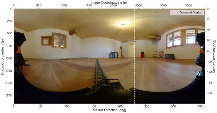
The International Archives of the Photogrammetry, Remote Sensing and Spatial Information Sciences, Volume XLIII-B1-2021
                                                XXIV ISPRS Congress (2021 edition)

continuously. The absolute orientation estimation is performed
as follows:

4.3.1 Initialisation Phase: With the first measurement, the
translation of the odom frame into the map frame can be
calculated. The origin of the odom frame is set to the prism
position. The estimation of the translation needs to occur while
the platform is not moving.

4.3.2 Check for recent Position: For every new camera
frame, the time difference between the camera frame and the
latest position estimation is estimated. If the difference is less
than one microsecond, the camera frame will be used for further      Figure 5. Horizontal and vertical direction of detected marker
computation.                                                         used for direction calculation in equirectangular camera frame

4.3.3 Marker Detection: In the case of a time-synced                 4.3.6 Calculation of possible Camera Locations: The
camera frame and prism position, an ArUco marker detection in        possible camera locations can be calculated using the horizontal
the current camera frame is performed. For the detection, the        direction of the marker, the horizontal distance between 360°
OpenCV       function    cv2.aruco.detectMarkers   (OpenCV:          prism and camera and the position of marker and 360° prism
Detection of ArUco Markers, n.d.) with subpixel refinement is        (Figure 6).
used. If a marker gets detected, the marker ID and the image
coordinates of the marker corners are returned.

                                                                     Figure 6. Calculation of possible camera locations: Current
Figure 4. Detected marker in cropped camera frame                    prism 3D position (black dot, position via tachymetry), marker
                                                                     3D position (blue dot), cosine solutions (blue, green) intersected
4.3.4 Marker Centre Calculation: Since the detected                  with leverarm camera->prism (red) gives possible camera
marker can be distorted, the marker centre is calculated by the      positions (black crosses). Most likely position (red) in direction
intersection of the two diagonals of the marker corners (Figure      of travel.
4).
                                                                     The possible camera locations are calculated with the cosine
4.3.5 Direction Calculation: From the coordinates of the             theorem, which returns four possible locations. The location,
marker centre and the image size, the horizontal and vertical        which is in the direction calculated from the prism tracking is
direction of the marker in respect to the camera can be              the most likely position and will be used.
calculated. If the camera model is equirectangular, this
calculation becomes simple, with other camera models or when         4.3.7 Odom Frame Adjustment: Finally, the orientation of
using an multi head system, the intrinsic and relative camera        the odom frame gets adjusted and the odometry trajectory is
calibration are needed (Figure 5).                                   absolutely oriented. During the initialization phase, the
                                                                     corrections are big, afterwards the corrections are only
                                                                     incremental and compensate only the drift of the odometry
                                                                     trajectory from the relative orientation estimation.

                                                This contribution has been peer-reviewed.
                 https://doi.org/10.5194/isprs-archives-XLIII-B1-2021-215-2021 | © Author(s) 2021. CC BY 4.0 License.              217
The International Archives of the Photogrammetry, Remote Sensing and Spatial Information Sciences, Volume XLIII-B1-2021
                                                XXIV ISPRS Congress (2021 edition)

4.4 Sensor Fusion                                                    However, the most continuous trajectory is obtained with the
                                                                     full resolution (3840x1920 pixels) and loop closure detection
To obtain the best possible estimate of the mobile platform's        disabled (Figure 9). With this configuration, the images can be
pose and to take advantage of redundancies in the determination      computed at just under 8 Hz. Since this configuration is not
of position and orientation, the position determinations by the      real-time capable, the relative orientation was calculated in
multistation and the absolute orientation are fused together.        advance for the further investigations.
Therefore, absolute orientation and position can be published at
the same rate as relative orientation determination. In addition,
other sensors such as odometers (wheel odometry) or IMU
could be included in the sensor fusion if they were available.
The sensor fusion is performed using the ROS package
robot_localization (Moore and Stouch, 2016). This package can
be used to configure a sensor fusion. The sensor fusion
calculates the robot pose at 30 Hz (same rate as camera frames).

            5. EXPERIMENTS AND RESULTS

5.1 Sensor Synchronisation                                           Figure 9. Horizontal drift: OpenVSLAM trajectory without
                                                                     loop closure for 13 laps (left) and evolvement of the horizontal
Due to the camera stream limitation, it was not possible to          drift (right)
acquire a synced dataset of camera stream and prism tracking.
Therefore, a sensor synchronisation needs to be conducted            5.3 Marker Detection
before the postprocessing. For the synchronisation, only the
time offset between the two datasets needs to be found. The          In the range study for the present combination of camera and
time offset can be determined via cross correlation of a common      ArUco markers, a marker was fixed in a large room and then a
phenomenon, in this case it is the heading of the mobile             picture was taken with a panoramic camera at different
platform. The heading from the relative orientation is compared      distances from the marker. The marker could be successfully
with the heading calculated from the prism tracking. The used        detected at a distance between 3 and 11 meters. From a distance
heading is the average between the heading towards the next          of 12 meters, the marker could no longer be detected in the
prism position and the previous position. Since the frequency of     camera image. The detected marker still has a size of about 9x9
the prism tracking is smaller than the frequency of the relative     pixels in the image at a distance of 11 meters with the panorama
orientation, the calculated prism headings are interpolated to the   camera used (Ricoh Theta Z1).
same frequency (Figure 7).
                                                                     5.4 Evaluation of the complete System

                                                                     To determine the accuracy of the absolute orientation, images
                                                                     were taken with the Lego Train platform in a room where four
                                                                     different markers (M1, M2, M3, M4) were placed at different
                                                                     locations (Figure 10).

Figure 7. Interpolation of the prism headings: original (red) and
interpolated (black)

Subsequently, the time offset between the measurements can be
calculated. The biggest correlation for the dataset used in the
evaluation (see Figure 8) occurred at an offset of 11 frames
(0.367 seconds). This offset was used for further processing.

Figure 8. Time offset between relative orientation estimation
(top) and prism tracking (bottom)

5.2 Relative Orientation Estimation
                                                                     Figure 10. Marker distribution (M1 – M4) on test site for
The relative orientation determination can be performed with
                                                                     evaluation
different parameterizations. To be able to perform the
determination in real-time, the resolution of the camera stream
                                                                     Subsequently, the absolute orientations were calculated four
must be reduced, the number of features to be detected must be
                                                                     times from the recordings. Each time, one of the four markers
reduced and the loop closure detection must be deactivated.

                                                This contribution has been peer-reviewed.
                 https://doi.org/10.5194/isprs-archives-XLIII-B1-2021-215-2021 | © Author(s) 2021. CC BY 4.0 License.            218
The International Archives of the Photogrammetry, Remote Sensing and Spatial Information Sciences, Volume XLIII-B1-2021
                                                XXIV ISPRS Congress (2021 edition)

was used for the absolute orientation correction. In this process,
the calculated poses from the sensor fusion were recorded and
subsequently compared with each other.
The RPE (relative pose error, relative pose deviation) (Sturm et
al., 2012) was used as a method for comparing every pose of the
trajectory calculated using the four different markers. The RPE
calculates the difference between two trajectories and is
commonly used to compare an estimated/calculated pose with
the true pose. The true pose is usually determined by another,
more accurate method, such as a motion capture system. Since
no such motion capture system was available for processing this
work, only the trajectories calculated with different markers
                                                                       Figure 13. Comparison of position of the marker detection on
were compared. On average, the orientation deviation is 1.17
                                                                       the camera sensor to odom frame adjustment
degrees with a mean standard deviation of 1.66 degrees.
                                                                                   6. CONCLUSION AND OUTLOOK
Figure 11 shows the change in horizontal orientation of the
calculated trajectories. On closer inspection, it is noticeable that   In this paper a new approach for high precision determination of
the orientation deviates constantly depending on the marker            absolute orientation was presented. The absolute orientation
used.                                                                  with an ArUco marker works well and it could be shown in a
                                                                       study with the Lego train platform that 50% of the
                                                                       determinations are more accurate than 0.66 degrees and the
                                                                       difference of the poses between the processed trajectories with
                                                                       different marker detection are on average 1.17 degrees. With
                                                                       this approach, the installation effort is very low: set up the total
                                                                       station, measure the markers, and the absolute orientation of the
                                                                       mobile platform can be determined. In order to increase the
                                                                       system accuracy, instead of using the factory calibration of the
                                                                       camera, a custom calibration would need to be performed and
                                                                       applied. Unfortunately, this was not possible in this work in the
                                                                       home office due to the special situation at the time of the
                                                                       investigations. In the future, multiple markers could be used to
Figure 11. Heading of absolute orientation during 10 laps              determine absolute orientation, thus all 6 degrees of freedom
                                                                       could be determined continuously. In addition, alternative
Figure 12 shows the individual orientation adjustments with the        markers could be searched for, which would increase the radius
respective marker used. There, too, at the beginning and the end       of action of the mobile platform.
(standstill of the platform) it is clearly visible that the that the
adjustments show a significant bias. Since the deviations are                                   REFERENCES
constant and also occur at standstill, the assumption is obvious
that the camera calibration still shows systematic errors.             Caron, G., Morbidi, F., 2018: Spherical Visual Gyroscope for
                                                                       Autonomous Robots Using the Mixture of Photometric
                                                                       Potentials. Proceedings - IEEE International Conference on
                                                                       Robotics and Automation, 820–827.
                                                                       https://doi.org/10.1109/ICRA.2018.8460761

                                                                       Garrido-Jurado, S., Muñoz-Salinas, R., Madrid-Cuevas, F. J.,
                                                                       Marín-Jiménez, M. J., 2014: Automatic generation and
                                                                       detection of highly reliable fiducial markers under occlusion.
                                                                       Pattern Recognition, 47(6), 2280–2292.
                                                                       https://doi.org/10.1016/j.patcog.2014.01.005

                                                                       Hartmann, W., Havlena, M., Schindler, K., 2015: Visual
                                                                       gyroscope for accurate orientation estimation. Proceedings -
Figure 12. Adjustments on odom frame horizontal orientation            2015 IEEE Winter Conference on Applications of Computer
over 10 laps                                                           Vision, WACV 2015, 286–293.
                                                                       https://doi.org/10.1109/WACV.2015.45
Further investigation into systematic errors were performed. A
comparison between the place of the marker detection in the            Irani, M., Anandan, P.; 2000: About direct methods. Lecture
camera frame and the resulting rotation of the odom frame              Notes in Computer Science (Including Subseries Lecture Notes
shows, that depending on where the marker gets detected in the         in Artificial Intelligence and Lecture Notes in Bioinformatics),
camera frame, the odom frame gets adjusted differently (Figure         1883, 267–277. https://doi.org/10.1007/3-540-44480-7_18
13).
                                                                       Moore, T., Stouch, D.; 2016: A generalized extended Kalman
                                                                       filter implementation for the robot operating system. Advances
                                                                       in Intelligent Systems and Computing, 302, 335–348.
                                                                       https://doi.org/10.1007/978-3-319-08338-4_25

                                                                       Morbidi, F., Caron, G., 2017: Phase Correlation for Dense

                                                This contribution has been peer-reviewed.
                 https://doi.org/10.5194/isprs-archives-XLIII-B1-2021-215-2021 | © Author(s) 2021. CC BY 4.0 License.                  219
The International Archives of the Photogrammetry, Remote Sensing and Spatial Information Sciences, Volume XLIII-B1-2021
                                                XXIV ISPRS Congress (2021 edition)

Visual Compass from Omnidirectional Camera-Robot Images.
IEEE Robotics and Automation Letters, 2(2), 688–695.
https://doi.org/10.1109/LRA.2017.2650150

Mur-Artal, R., Tardos, J. D., 2017: ORB-SLAM2: An Open-
Source SLAM System for Monocular, Stereo, and RGB-D
Cameras. IEEE Transactions on Robotics, 33(5), 1255–1262.
https://doi.org/10.1109/TRO.2017.2705103

OpenCV: Detection of ArUco Markers., n.d.:
https://docs.opencv.org/master/d5/dae/tutorial_aruco_detection.
html (21 January 2021)

Sattler, T., Maddern, W., Toft, C., Torii, A., Hammarstrand, L.,
Stenborg, E., Safari, D., Okutomi, M., Pollefeys, M., Sivic, J.,
Kahl, F., Pajdla, T., 2018: Benchmarking 6DOF Outdoor Visual
Localization in Changing Conditions. Proceedings of the IEEE
Computer Society Conference on Computer Vision and Pattern
Recognition, 8601–8610.
https://doi.org/10.1109/CVPR.2018.00897

Sturm, J., Engelhard, N., Endres, F., Burgard, W., Cremers, D.,
2012: A benchmark for the evaluation of RGB-D SLAM
systems. IEEE International Conference on Intelligent Robots
and Systems, September 2015, 573–580.
https://doi.org/10.1109/IROS.2012.6385773

Sumikura, S., Shibuya, M., Sakurada, K., 2019: OpenVSLAM:
A Versatile Visual SLAM Framework. Proceedings of the 27th
ACM International Conference on Multimedia, 2292--2295.
https://doi.org/10.1145/3343031.3350539

                                               This contribution has been peer-reviewed.
                https://doi.org/10.5194/isprs-archives-XLIII-B1-2021-215-2021 | © Author(s) 2021. CC BY 4.0 License.           220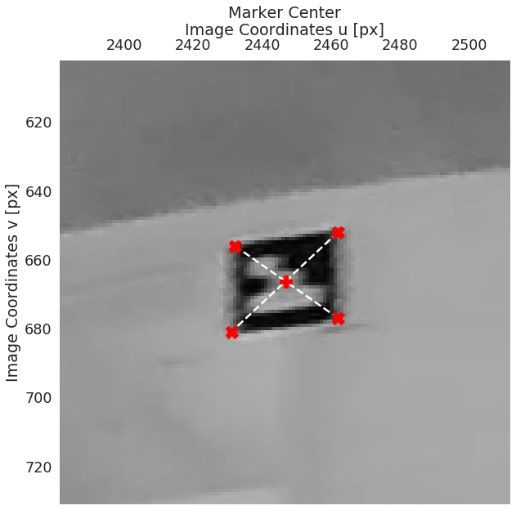


You can also read