Interconnect Technologies You Need on Your Aircraft NOW - APRIL 2019 - Glenair Electric
←
→
Page content transcription
If your browser does not render page correctly, please read the page content below

GLENAIR   •   APRIL   2019   •   VOLUME   23   •   NUMBER   2

               Interconnect Technologies
               You Need on Your Aircraft NOW
Electrical Wiring Interconnect System:
                              Zone-by-Zone Design Guide
A “Systems Approach” to Aircraft Interconnect Cabling
Commercial aircraft manufacturers treat large, interdependent equipment sets as systems: avionics, galleys, cabin
lighting, HVAC, IFE, navigation, and so on. The systems are designed with performance
benchmarks tied to the environmental stress factors of the different zones of the
aircraft where they are used. The cables and harnesses that interconnect these
equipment sets, the Electrical Wiring Interconnect System (EWIS), is also now treated
as a discrete system within the aircraft, subject to different requirements and
specifications depending on the zones where it is located. In the past, the EWIS
was treated more as an afterthought, with insufficient consideration given to
best-practice design and zone-by-zone performance standards. The FAA, with
the support of the principal aircraft manufacturers, has over the last several
decades taken steps to change how interconnect technology is specified and
managed. The key element of this effort was the move to treat wiring and
associated interconnect components as a discrete system in its own right. The
Electrical Wiring Interconnection System is now defined as: any wire, wiring device,
or combination, including termination devices, installed in any area of the airplane,
used to transmit electrical energy between two or more intended termination points.

EWIS Performance
Historically, wiring and interconnect components were installed in aircraft in a “fit and forget” manner—without
sufficient thought given to different aging and degradation impacts on a zone-by-zone basis. While the FAA has always
outlined the top-level variables in EWIS degradation including aging, physical properties, installation and environment,
and maintenance, cleaning and repair, it is only recently that these environmental stress factors have been exactingly
evaluated according to aircraft zones. Service history shows it is not just the manner by which EWIS is installed that
directly affects degradation, but more importantly material choices, environmental sealing components, EMC shielding
technologies and so on that are geared for the unique stress factors found throughout the aircraft. Today’s EWIS
                                        designers use DO-160 Environmental Conditions and Test Procedures for Airborne
                                          Equipment to ensure every element of the Electrical Wiring Interconnect
                                                                System meets or exceeds requirements for vibration,
                                                                   shock, ground survival temperature, pressure
                                                                     differential, operating temperature, and moisture
                                                                      in each specific zone of the aircraft.

                                                                     Designing, Installing
                                                                     and Repairing EWIS
                                                                    Many factors identified by the FAA must be
                                                                    considered when designing, installing or repairing
                                                                    an Electrical Wire Interconnect System, as follows:

2                                                                                                     QwikConnect • April 2019
GLENAIR

     Electrical Load Determination
     System designers must ensure that each aircraft electrical bus can safely support the load
     based on the electrical capacity of the aircraft’s electrical generators and distribution
     system. All electrical devices must be safely controlled or managed by the aircraft’s
     electrical system, and whenever a device is added, a load analysis should be performed to
     ensure that the new load on the bus can be powered adequately.

     Wire Selection: Size, Substrate, Plating, and Insulation
     Wires should be sized so that they have sufficient mechanical strength, do not exceed
     allowable voltage drop levels, are protected by circuit protection devices, and meet circuit
     current-carrying requirements. Small gauge wires should use high-strength alloy conductors
     and additional support at terminations (grommets, shrink sleeves, etc.) to minimize fatigue.
     Wires should be plated to defend against surface oxidation. Elevated temperature degradation of
     tin- and silver-plated copper conductors will occur if they are exposed to continuous high-temperature
     operation.
     While there is no “perfect” insulation system for aerospace wire and cable, the EWIS designer must consider the best
     balance of properties (electrical, mechanical, chemical, and thermal) for each application.

     Determining Current-Carrying Capacity
     EWIS designers must verify that the maximum ambient temperature wire bundles will be subjected to, plus the
     temperature rise due to wire current loads, does not exceed the maximum conductor temperature rating. In smaller
     harnesses, the allowable percentage of total current may be increased as the harness approaches the single wire
     configuration. Care should be taken to ensure that the continuous current value chosen for a particular
     system circuit does not create hot spots within any circuit element which could lead to
     premature failure.

                                         Causes of EWIS Degradation
     Vibration: High-vibration areas tend to accelerate degradation         Chemical contamination: Chemicals such as hydraulic fluid,
     over time, resulting in “chattering” contacts and other                fuel, waste system chemicals, cleaning agents, deicing fluids, and
     intermittent problems. It can also cause tie-wraps to damage           even soft drinks can contribute to EWIS degradation. EWIS in the
     insulation, and exacerbate insulation cracking.                        vicinity of these chemicals should be inspected for damage or
     Moisture: High-moisture zones accelerate corrosion of                  degradation. Hydraulic fluids, for example, are very damaging
     interconnect components. EWIS installed in clean, dry areas with       to connector grommet and wire bundle clamps, and can lead to
     moderate temperatures hold up well.                                    indirect damage such as arcing and chafing. EWIS components
     Maintenance and repair: Improper maintenance techniques                potentially exposed to hydraulic fluid should be given special
     can contribute to EWIS degradation—for example, leaving                attention during inspections.
     metal shavings or debris behind after a repair. Wire bundles and       Heat: High heat can accelerate degradation, insulation dryness,
     connectors should be protected during modification work, and           and cracking. Even low levels of heat can degrade EWIS over long
     all debris must be cleaned up after work is completed. Generally,
                                                                            periods of time. This type of degradation can be seen on engines,
     EWIS left undisturbed will have less degradation than reworked
                                                                            in galleys, and behind lights.
     EWIS. As EWIS become more brittle with age, this effect becomes
     more pronounced. Repairs that conform to manufacturer’s                Improper installation: Improper installation can accelerate
     recommended maintenance practices are generally considered             degradation. Improper routing, clamping, and terminating
     permanent and should not require rework if properly maintained.        during initial installation or during modifications can lead to
     Indirect damage: Events such as pneumatic duct ruptures can            EWIS damage. FAA policy states that installation and routing
     cause damage that, while not initially evident, can later cause EWIS   instructions should be completely defined in detail to allow
     problems. When such an event has occurred, surrounding EWIS            repeatability of installation, not leaving installation to the
     should be carefully inspected to ensure no damage is evident.          discretion of the installer.
QwikConnect • April 2019                                                                                                                      3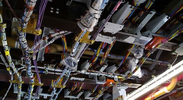
Wire Substitution for Repairs and Maintenance
                                         EWIS manufacturers are required to perform rigorous qualification testing
                                         of wires. The original aircraft manufacturer (OAM) may have special concerns
                                        regarding shielding and insulation for certain wiring that performs critical
                                        functions, or wiring chosen based on a set of unique circumstances. It is
                                       important to review the aircraft maintenance manual or contact the OAM when
                                      wire replacement is required.

                                   EWIS Routing
                                 In general, EWIS should be routed and positioned to avoid chafing against aircraft
                              structure or other components, to eliminate or minimize use as a handhold or support, to
                          minimize exposure to damage by maintenance crews or shifting cargo, and to avoid exposure
                    to corrosive fluids. Extra wire length should be supplied to allow for at least two re-terminations.
EWIS components must be protected in wheel wells and other areas where they may be exposed to damage from
impact of rocks, ice, mud, etc.
Where practical, EWIS should be routed above fluid lines. Wires and cables routed within 6 inches of any flammable
liquid, fuel, or oxygen line should be closely clamped and rigidly supported. The compression clamps should be spaced
so that if there is a wire break, the broken wire will not contact hydraulic lines, oxygen lines, pneumatic lines, or other
equipment whose subsequent failure caused by arcing could cause further damage.
For all types of wire breakouts—“Y,” “T,” and complex multi-branch—there should be sufficient slack in the breakout
wires to avoid strain. Care should be taken when plastic tie wraps are used so that the tie wrap head does not cause
chafing damage to the wire bundle at the breakout junction.
The EWIS design should preclude wire bundles from contacting the aircraft structure, using stand-offs to maintain
clearance. Employing tape or protective tubing as an alternative to stand-offs should be avoided.

Clamping and cable ties
Clamps and cable ties must be constructed of appropriate materials for their installation
environment. Clamps must be properly sized for their wire bundles, snug enough to
prevent free movement and chafing, and not used where their failure could result
in interference with crucial aircraft controls or movable equipment. Clamps must
be installed with their attachment hardware positioned above them so they are
unlikely to rotate as the result of wire bundle weight or wire bundle chafing. Wire
bundles need to be routed perpendicular to clamps. Appropriate slack needs to
be maintained between clamps to protect the wires from stress while keeping
the bundle free from contacting the structure. Also, sufficient slack should be left
between the last clamp and the termination or electrical equipment to prevent
strain at the terminal.

Wire Bend Radii
The minimum radii of bends in wire groups or bundles must not be less than 10 times
the outside diameter of the largest wire or cable, except that at the terminal strips where
wires break out at terminations or reverse direction in a bundle. The bend radius for delicate
thermocouple wire is 20 times the diameter, and for RF cables (e.g. coaxial and triaxial) is no less
than 6 times the outside diameter of the cable.

Unused Wires and Excess Wire
Ensure unused wires are individually dead-ended, tied into a bundle, and secured to a permanent structure. Each
wire should have strands cut even with the insulation and a pre-insulated closed end connector or a 1-inch piece of
insulating tubing placed over the wire with its end folded back and tied.
Coil and stow methods are often used to secure excess length of a wire bundle or to secure unconnected spare bundles.
The wire bundle must be secured to prevent excessive movement or contact with other equipment that could damage
the EWIS. Coil and stow in medium and high vibration areas requires additional tie straps, sleeving, and support.
4                                                                                                        QwikConnect • April 2019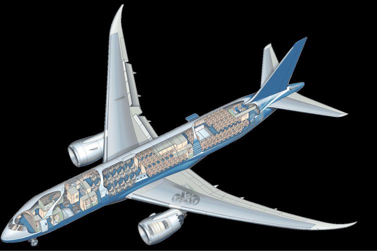
GLENAIR

     Wire Splicing
     Improperly crimped splices can cause increased resistance, leading to overheating. Splicing should be kept to a
     minimum and avoided in high-vibration areas. Splicing of power wires, co-axial cables, multiplex bus, and large gauge
     wire should be avoided. Self-insulated splice connectors and environmentally-sealed AS7928 conformant splices are
     preferred. Splices should be located to permit inspection, and splices in bundles should be staggered so as to minimize
     any increase in the size of the bundle.

     Grounding and Bonding
     One of the more important factors in the design and maintenance of aircraft electrical systems is proper bonding
     and grounding—the process of electrically connecting conductive objects to a conductive structure or return path to
     complete a circuit. Inadequate bonding or grounding can lead to unreliable operation of systems, damage to sensitive
     electronics, shock hazard, or lightning strike damage. The design of the ground return circuit should be given as much
     attention as the other leads of a circuit.
     Low impedance paths to aircraft structure are normally required for electronic equipment to provide radio
     frequency return circuits, and for most electrical equipment to facilitate EMI reduction. Component cases producing
     electromagnetic energy should be grounded to the structure.
     All conducting objects on the exterior of the airframe must be bonded through mechanical joints, conductive hinges, or
     bond straps capable of conducting static charges and lightning strikes.

     EWIS Identification
     The proper identification of EWIS components with their circuits and voltages is necessary to provide safe operation
     and ease of maintenance. Each wire and cable should be marked with a part number and CAGE code so that it can
     be identified as to its performance capabilities, preventing the inadvertent use of lower performance and unsuitable
     replacement wire. Unmarked cables are more likely to be reconnected improperly which could cause numerous
     problems.

     Best Practices for EWIS
     The number and complexity of EWIS has resulted in an increased use of electrical connectors for flexibility and modular
     replacement of electronic equipment. The proper choice and application of connectors is a significant part of the aircraft
     EWIS system. Connectors should be selected and installed to provide maximum safety and reliability to the aircraft.
     • The connector used for each application should be selected only after a
        careful determination of the electrical and environmental requirements.
        Consider the size, weight, tooling, logistic, maintenance support,
        and compatibility with standardization programs.
     • For ease of assembly and maintenance, connectors using
        crimped contacts are generally chosen for all applications
        except those requiring a hermetic seal.
     • Proper insertion and extraction tools should be used to
        install or remove wires from connectors.
     • Connectors susceptible to corrosion may be treated
        with a chemically inert waterproof jelly, or an
        environmentally-sealed connector may be used.
     • Moisture-proof connectors should be used in all zones
        of the aircraft, including the cabin. Service history
        indicates that most connector failures occur due to some
        form of moisture penetration. Even in the pressurized,
        environmentally-controlled zones of the cockpit and cabin,
        moisture can occur due to condensation.
     • Consideration should be given to the design of the pin
        arrangement to avoid situations where pin-to-pin shorts could
        result in multiple loss of functions and/or power supplies.
QwikConnect • April 2019                                                                                                      5
COMMERCIAL AIRCRAFT
Electrical Wiring
Interconnect Systems
Aircraft Zones and Glenair Signature
Series Interconnect Technologies
T  his interconnect design and application guide is broken down into traditional
   aircraft zones as defined in RTCA/ DO-160. Interconnect technology for individual
sections and equipment-sets within each zone is presented in enough detail to
enable EWIS designers to understand the broad range of options available and
make sound specifications within each area of responsibility. Leveraging the talents
of EWIS engineer Bob Johnson, Glenair has developed a number of Signature                    ZONE 7: EMPENNAGE AND
interconnect technologies for commercial aircraft, which are presented in the                VERTICAL STABILIZER TIP
context of each zone.                                                                               High Vibration
                                                                                              Extreme Temperature Range
                                                                                                    -55° to +200°C
                                       AIRCRAFT ZONES:                                             De-Icing Exposure
1. Fuselage                                                                                     Wide Pressure Changes
2. Instrument Panel Console and Equipment Rack
3. Nacelle and Pylon
4. Engine and Gear Box
5. Wing and Wheel Well
6. Landing Gear
7. Empennage and Vertical Stabilizer Tip
8. Cabin interior volume

To assist designers in the specification of appropriate interconnect components
for use in each zone, each spread in this document presents applicable “DO-160
Environmental Conditions and Test Procedures for Airborne Equipment,” and the
Glenair interconnect technologies that meet or exceed these requirements. As
application guidelines for key environmental stress factors including vibration,
shock, ground survival temperature, pressure differential, operating temperature,
and moisture can change with each zone, only those applicable specification
references are noted.

CATALOG VERSUS CUSTOM / TAILORED TECHNOLOGIES
This design guide primarily presents proven-performance electrical interconnect technologies that can be sourced
directly from catalog offerings. This includes the Bob Johnson signature series technologies which are highlighted for
each zone. Designers looking to resolve long-standing problems or improve performance in such areas as size, weight,
and power frequently turn to custom / tailored solutions. In both events, selections must be aligned with Federal Aviation
Administration 14 CFR 25.1701 which states that EWIS components must be of a kind and design appropriate to its
intended function and perform the function for which it was intended without degrading the airworthiness of the airplane.
Responsibility for these determinations resides with the aircraft manufacturer.
                                                                                                        QwikConnect • April 2019
GLENAIR

     DO-160, ENVIRONMENTAL CONDITIONS AND TEST
     PROCEDURES FOR AIRBORNE EQUIPMENT AND
                                                                                              ZONE 2: INSTRUMENT PANEL,
     AIRCRAFT ZONES                                                                         CONSOLE, AND EQUIPMENT RACK
     Effective EWIS design is best accomplished by aligning DO-160,                                       Pressurized
     Environmental Conditions and Test Procedures for Airborne                                 Fluids - Condensation, Humidity
     Equipment, with the empirical environmental performance levels                        Typical Temperature Range -65° to +95°C
     targeted for each zone, section, and equipment set on the aircraft.                     Moderate Dynamic Vibration Range
                                                                                              Flammability, Smoke, and Toxicity
                                                                                                         Requirements
                                       ZONE 1: FUSELAGE
                                             Pressurized
                                  Fluids - Condensation, Humidity
                              Typical Temperature Range -65° to +95°C
                                Moderate Dynamic Vibration Range
                           Flammability, Smoke, and Toxicity Requirements

                                                                                  ZONE 8: CABIN INTERIOR VOLUME
                                                                                                Pressurized
                                                                                     Fluids - Condensation, Humidity
                                                                                 Typical Temperature Range -65° to +95°C
                                                                                   Moderate Dynamic Vibration Range
                                                                                    Flammability, Smoke, and Toxicity
                                                                                               Requirements

     ZONE 6: LANDING GEAR                                                                ZONE 4: ENGINE AND GEAR BOX
           High Vibration                                                                  Dynamic Vibration Environment
      Wide Temperature Range                                                                Extreme Temperature Range
           -55° to +150°C                                                                          -65° to +200°
          Fluid Exposure                                                                              Firewall
      Wide Pressure Changes                                                                       Fuels and Fluids

                   ZONE 5: WING AND WHEEL WELL                              ZONE 3: NACELLE AND PYLON
                             High Vibration                                 Dynamic Vibration Environment
                       Extreme Temperature Range                             Extreme Temperature Range
                             -55° to +200°C                                         -65° to +200°
                             Fluid Exposure                                            Firewall
                         Wide Pressure Changes                                     Fuels and Fluids

     AIRCRAFT ZONES: MACRO ENVIRONMENTS
     Significant variability exists between the various macro environments of a modern commercial aircraft (dynamic
     stimulus, moisture, humidity, thermal extremes, and so on). Environmental stress factors place a demand on the electrical
     interconnect components that must perform for the expected life of 20 years. Macro environments range from the cabin
     interior—where the challenge is mainly moisture / humidity—to extreme unpressurized zones such as wing and wheel
     wells where extreme dynamic stimuli combined with thermal extremes can rapidly degrade the performance and life
     expectancy of interconnect technologies.

QwikConnect • April 2019                                                                                                         7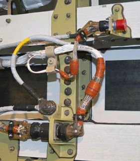
Qualified Glenair Interconnect
                                             Technologies for Aircraft Electrical
                                             Wiring Interconnect Systems
                                             Organized by type with zone designators
ELECTRICAL CONTACTS / SEALING CONTACTS • Suitable for use in Aircraft Zones 1, 2, 3, 4, 5, 6, 7, and 8

    Standard and high-          Extended-duty               High-speed, RF, and          Lightweight sealing plugs
       density signal       signal (up to 1500 cycles)      El Ochito® contacts         and dummy sealing contacts

ULTRAMINIATURE CIRCULARS • Suitable for use in Aircraft Zones 1, 2, 3, 4, 5, 6, 7, and 8

    Series 806 Mil-Aero: small form-factor                 Series 806 Mil-Aero                      Series 806 Mil-Aero
        equivalent for MIL-DTL-38999                     glass-sealed hermetics                  CODE RED-sealed hermetics

MIL-AERO CIRCULARS • Suitable for use in Aircraft Zones 1, 2, 3, 4, 5, 6, 7, and 8

        QPL MIL-DTL-38999 Series III            SuperNine® MIL-DTL-38999 Series III +       SuperNine® MIL-DTL-38999 Series III +
       Suitable for Zones 1 and 2 only             Better than QPL™ performance             glass- and CODE RED-sealed hermetics

HIGH-SPEED DATALINK CONNECTORS • see below for zone designators

      SuperSeal™ MIL-DTL-38999 RJ45              SuperSeal™ MIL-DTL-38999 USB 2.0             GateLink Pro high-speed data uplink
       Suitable for Zones 1, 2, and 8               Suitable for Zones 1, 2, and 8                    Suitable for Zone 2
8                                                                                                                 QwikConnect • April 2019
FIBER OPTICS • Suitable for use in Aircraft Zones 1, 2, 3, 4, 5, 6, 7, and 8

      SuperNine® MIL-DTL-38999 Series III type                 Series 806 Mil-Aero                     Qualified fiber optic termini
            tight-tolerance fiber optics                    high-density fiber optics

     POWER CONNECTORS AND PRESSURE BOUNDARY FEEDTHRUS • see below for zone designators

     PowerLoad™ power distribution connectors           PowerLoad™ bulkhead feedthru            Pressure boundary and firewall feedthrus
         Suitable for Zones 1, 2, 3, 4, and 7          Suitable for Zones 1, 2, 3, 4, and 7              Suitable for Zones 1 – 7

     EMI/RFI BRAIDED SHIELDING AND PROTECTIVE COVERING • Suitable for use in Aircraft Zones 1 – 8

       Band-Master ATS® advanced            ArmorLite microfilament            Lightweight, flexible           MasterWrap side-entry
        shield termination system              EMI/RFI shielding              ground straps and HSTs           wraparound shielding

     CONNECTOR BACKSHELLS AND ACCESSORIES • Suitable for use in Aircraft Zones 1 – 8

           ProSeal spring-action                Environmental                    Swing-Arm FLEX              Swing-Arm standard and
             protective covers                 protective covers               composite backshells      wide-mouth composite backshells

     SPECIAL-PURPOSE EWIS TECHNOLOGIES • see below for zone designators

       Advanced rectangular aviation         Receptacle / bulkhead         SpliceSaver time- and labor- Polymer- and metal-core conduit
       backshells (ARINC 600 shown)           connector nut plates        saving wire splice replacement      wire protection systems
      Suitable for Zones 1, 2, 5, 6, 7, 8   Suitable for Zones 1 – 8      Suitable for Zones 1, 2, 7, and 8 Suitable for Zones 5, 6, and 8

QwikConnect • April 2019                                                                                                                   9
ZONE 1
Fuselage Mid-Wing
Forward barrel section plus
center section and aft-of-wing
barrel section (pressurized
passenger / crew cabin)
T he main passenger cabin, crew and galley areas are housed in the fuselage
mid-wing. This pressurized zone is characterized by moderate environmental
stress factors such as fluid condensation, humidity, temperatures in the -65° to
Glenair SpliceSaver™
Crimp wire termination
+95°C range, and moderate dynamic vibration. The electrical wiring interconnect solution saves time and
system utilizes mostly conventional interconnect technology, with an emphasis on labor over manual DO150
general weight reduction, reliability, and speed-of-assembly. Production breaks splicing
are a significant challenge for the EWIS engineer, with cost control of interconnect Ideally suited for crown
interfaces a principal design requirement. The pressurized interface between the and floor wiring in Zone 1
mid-wing fuselage and the wings requires careful attention in the specification and Three versions: single-
use of pressure bulkhead feedthrus. piece, Spiralock®, and
bussed
Zone 1 Application Guidelines
Environmental Stress Factors Applicable RTCA/DO-160 Requirements
Features Stinger™ crimp
Vibration DO-160 Category S and H (Table 8-1)
contact technology with
Shock DO-160 Category A, Test Procedure 1
integrated retention
Ground Survival Temperature -65° to 95°C; DO-160 Category A3 (Table 4-1)
mechanism
Pressure Differential Sea level to 10kft; DO-160 Category A3 (Table 4-1) Small form-factor and
-55° to 85°C; DO-160 category A3 (Table 4-1) with Temperature lightweight composite
Operating Temperature
change rate per DO-160 Category A (10 C min per minute) Supports 1–3 wire
Moisture Exposure to humidity and condensation; DO-160 Category B terminations
10ZONE 1 GLENAIR
Fuselage Mid-Wing
Glenair standard and signature
interconnect technologies
Crown Wiring
SATCOM / Ku Band Antennas,
IFE, Lighting, Cabin Audio
System, Oxygen System,
Redundant Electrical Systems
Production Break
Aft Pressure Bulkhead
Feedthru Connectors, Pressure
Seal Bulkhead Feedthrus
Below Passenger Floor Wiring
Left and Right Main Longitudinal Wiring Runs,
Cargo Hold Wiring, Flight Control Wiring,
Generator and APU Power Feeders
Electrical Feedthrus
to Main Landing Gear
Electrical Feedthrus
and Pressure Seals
Wing and Engine Control
Wiring / Sensors
Qualified Glenair Technologies for Zone 1: Fuselage Mid-Wing
• SuperNine® MIL-DTL-38999 Series III + • Advanced rectangular aviation backshells
• SuperSeal™ RJ45 and USB 2.0 • Series 806 Mil-Aero nut plates
• MIL-DTL-38999 Series III Fiber Optics • Band-Master ATS® shield termination system
• Series 806 Mil-Aero High-Performance Ultraminiature • ArmorLite™ lightweight microfilament EMI/RFI braid
• Series 806 Mil-Aero Fiber Optics • ArmorLite™ ground straps
• AS39029 signal / high-speed contacts / El Ochito® • MasterWrap™ side-entry EMI/RFI shielding
• DCSP Dummy Contact Sealing Plugs • SpliceSaver™ connectors
• ProSeal™ spring-action protective covers • PowerLoad™ connectors and bulkhead feedthrus
• Connector protective covers • Pressure seal bulkhead fittings
• Swing-Arm FLEX® composite backshells • Hermetic connectors
11LABOR-SAVING
EWIS SPLICE Crimp wire termination
CONNECTOR solution saves time and labor
over manual DO150 splicing
Glenair SpliceSaver™ reduces manual wire
splice and terminal block operations
S pliceSaver™ is an innovative interconnect technology developed by Glenair for
use in aircraft wiring operations that rely on heat shrink splicing of aircraft signal,
sensor, and data transmission wiring. Single-piece SpliceSaver designs allow remote
Lightweight construction
Conductive (plated) or
non-conductive versions
harness assembly facilities to pre-terminate each line with a crimp-and-poke contact.
During aircraft wire harness installation, cabling is routed to interconnection points Crimp contact technology:
and the contact-equipped wires are quickly and easily installed into the lightweight front release/rear removal
single-piece SpliceSaver connector. Two-piece Spiralock® SpliceSaver designs enable Three to nineteen
the harness facility to terminate wires to the small form-factor, lightweight “connector” circuits per unit
for subsequent mating on the aircraft. A special bussed version is also available. All Environmentally sealed
SpliceSaver styles feature integrated banding platforms for the termination of EMI
Full-mate indicator
shielding utilizing qualified banding technology—one-piece design features three
platforms for termination at both ends and in the center. Compared to legacy terminal Replaces labor-intensive
blocks and wire splice technology, SpliceSaver offers faster, cleaner, and more reliable terminal blocks and
routing and termination of discrete wiring. splices
12ZONE 1 FEATURED TECHNOLOGY GLENAIR
SpliceSaver™ Fast and reliable replacement
for wire splice and terminal block technologies
SPLICESAVER AVAILABLE CONFIGURATIONS—FEATURES AND SPECIFICATIONS
Triple ripple grommet
wire seal for sealing at
high altitude
Machined contact
utilizes mil-spec crimp
tooling
Contacts are removable
allowing corrections to
circuits during testing if
required
Single-Piece
SpliceSaver™
Specifications
Altitude immersion:
75,000 ft.
DWV rating at altitude:
>800 V
Dielectric Withstanding
Voltage Ratings:
22AWG = 5 amps/contact
20AWG = 7.5 amps/contact
Material and finish options
(for compatibility with available
EMI/RFI braid materials):
Cadmium-plated aluminum
Nickel-plated aluminum
Nickel-plated brass
Spiralock® Threaded
SpliceSaver™
Weight Analysis
Receptacle connector:
1.6 grams including contacts
and seals
Plug connector:
1.66 grams including contacts
and seals
Total connector mass:
5.66 grams (all contact locations
installed)
Accessories: Add the variable
mass of two or three nano
bands trimmed to length of
grooves in the split sleeve
Bussed
13ZONE 2
Instrument Panel
Console and
Equipment Rack
Within the forward fuselage
T he instrument panel console and equipment rack zone of the aircraft, Zone 2, is
housed within the forward section of the fuselage. Zone 2 has the most diverse
range of interconnect technologies found in the aircraft, meeting a diverse set
GateLink Pro™
High-speed data uplink
of application and performance requirements. This section includes the flight connector for gate-to-
deck with its extensive set of avionic displays, control panels, communications aircraft applications
equipment, data uplink and downlink interfaces, antennae, and so on. These Ideally suited for Zone 2
equipment sets interface with the avionics and flight management computers
Durable pogo pin contact
located in the lower part of the forward fuselage in the equipment bay. The
system rated to tens of
equipment bay also hosts power panels and power conversion panels located
thousands of mating
adjacent to the equipment racks. This section of the aircraft may also contain a
cycles
galley, depending on airline configuration.
Sealed receptacle
available with ProSeal™
Zone 2 Application Guidelines
spring-action protective
Environmental Stress Factors Applicable RTCA/DO-160 Requirements
covers
Vibration DO-160 Category S and H (Table 8-1)
Shock DO-160 Category A, Test Procedure 1
Rugged overmolded plug
Ground Survival Temperature -65° to 95°C; DO-160 Category A3 (Table 4-1)
cable (turnkey)
Pressure Differential Sea level to 10kft; DO-160 Category A3 (Table 4-1) Environmentally sealed
-55° to 85°C; DO-160 category A3 (Table 4-1) with Temperature breakaway design
Operating Temperature
change rate per DO-160 Category A (10 C min per minute) Proven commercial
Moisture Exposure to humidity and condensation; DO-160 Category B airframe performance
14 QwikConnect • April 2019ZONE 2 GLENAIR
Instrument Panel Console / Equipment Rack
Glenair standard and signature
interconnect technologies
Flight Deck Avionics
Gatelink
Production Break
Equipment Bay Racks
Forward Bulkhead
Pressure Seal Bulkhead
Connectors and Feedthrus
Qualified Glenair Technologies for Zone 2: Instrument Panel Console and Equipment Rack
• MIL-DTL-38999 Series III QPL • Swing-Arm FLEX® composite backshells
• SuperSeal™ RJ45 and USB 2.0 • Advanced rectangular aviation backshells
• MIL-DTL-38999 Series III Fiber Optics • Band-Master ATS® shield termination system
• Series 806 Mil-Aero High-Performance Ultraminiature • ArmorLite™ lightweight microfilament EMI/RFI braid
• Series 806 Mil-Aero Fiber Optics • ArmorLite™ ground straps
• Series 79 ultraminiature crimp rectangulars • MasterWrap™ side-entry EMI/RFI shielding
• AS39029 electrical contacts • SpliceSaver™ connectors
• DCSP Dummy Contact Sealing Plugs • PowerLoad™ connectors and bulkhead feedthrus
• ProSeal™ spring-action protective covers • Pressure seal bulkhead fittings
• Connector protective covers • Hermetic connectors
QwikConnect • April 2019 15HIGH-SPEED
QUICK-DISCONNECT
GateLink Pro™
DATA UPLINK High-Speed Data
Uplink Connector
Durable pogo pin
Environmentally-sealed contact system rated
breakaway design for high-speed to tens of thousands
mating cycles
data transfer between terminal gate Sealed receptacle
and aircraft available with ProSeal
spring-action protective
G atelink Pro™ connectors are exactingly designed to meet the needs of airport cover
terminal-to-aircraft data uplinks. The IP68 sealed receptacle connector on the Straight or right-
aircraft is designed for low profile environmental performance (available ProSeal™ angle AutoShrink wire
protective cover adds additional environmental protection). Plug connectors are protection boots or
ruggedized for rough handling with pogo pin contacts and retention springs recessed rugged overmolded
deep into the plug to prevent damage. Designed for fast and reliable high-speed plug assemblies for
Ethernet data transfer up to 1Gb / second. Turnkey overmolded cable assemblies as reliable environmental
well as discrete connectors and environmental shrink boots are available. protection
16 QwikConnect • April 2019ZONE 2 FEATURED TECHNOLOGY GLENAIR
GateLink Pro™
IP68 sealed high-speed data uplink connector
GATELINK PRO APPLICATIONS AND SOLUTIONS
Wired datalink interconnect access to the aircraft from the airline terminal gate supports various information domains
and data types including aircraft traffic control, airline information services, passenger entertainment, weather, and so on.
Airline operating center applications (flight plans, schedules, advisories) are quickly and reliably uploaded to the aircraft
during turnarounds at the gate. Mechanical and environmental damage to the datalink interface is a common problem
solved by GateLink Pro.
Overmolded environmental plug. IP68 sealed receptacle. CAD drawing Mated GateLink Pro™ plug and
CAD drawing shows polarized shape shows integrated ProSeal™ protective receptacle. CAD drawing shows
of mating interface as well as internal cover and Autoshrink™ environmental shielded twisted pair cabling and
sealing and retention spring. sealing / strain relief boot. overmold cross-section of available
turnkey cable assembly
GATELINK PRO SPECIFICATIONS GATELINK PRO AVAILABLE ACCESSORIES
Voltage rating 500 VAC
Anti-vibration and shock spring-action solution •
Current rating 5 amps Self-aligning environmental seals
Contact resistance 20 milliohms maximum
Plug-to-receptacleZONE 3
Nacelle and Pylon
Immediate adjacency to
engine and gear box plus wing
and wheel well
Firewall and Pressure
T his zone of the aircraft experiences high vibration, heat, frequent maintenance
cycles, and susceptibility to chemical contamination. There are critical variable
temperature zones within the engine cowling. Typically, the region around the fan
Boundary Feed-Thrus
High-grade engineering
is cooler, with temperatures in the range of 85°– 95°C. Aft of the fan, temperatures thermoplastic or machined
increase dramatically. Design coordination with the aircraft manufacturer is metal
required for all EWIS technologies routed in and out of the nacelle and via the pylon. Solid and split-shell
versions
Zone 3 Application Guidelines Ideally suited for pressure,
Environmental Stress Factors Applicable RTCA/DO-160 Requirements vapor, and firewall
Vibration DO-160 Category S and H (Table 8-1) bulkheads throughout the
Shock DO-160 Category D, Test Procedure 1 aircraft including Zone 3
Ground Survival Temperature -65° to 200°C; DO-160 Category D3 O-ring sealed panel and
Pressure Differential Sea level to 50kft; DO-160 Category D3 box mounting interface
Operating Temperature -55° to 200°C; DO-160 category D3 Conductive and non-
Moisture Exposure to humidity and condensation; DO-160 Category B conductive finish options
18 QwikConnect • April 2019ZONE 3 GLENAIR
Nacelle and Pylon
Glenair standard and signature
interconnect technologies
Engine Firewall
High-Temperature
Bulkhead Connectors
and Pressure Boundary
Feedthrus
Nacelle
Thrust Reversers
Pylon
Vapor Seal
Electrical Connectors
Nacelle
Qualified Glenair Technologies for Zone 3: Nacelle and Pylon
• SuperNine® MIL-DTL-38999 Series III + • Swing-Arm composite and SS backshells
• MIL-DTL-38999 Series III Fiber Optics • Band-Master ATS® shield termination system
• Series 806 Mil-Aero Fiber Optics • ArmorLite™ lightweight microfilament EMI/RFI braid
• AS39029 electrical contacts • ArmorLite™ ground straps
• DCSP Dummy Contact Sealing Plugs • PowerLoad™ connectors and bulkhead feedthrus
• ProSeal™ spring-action protective covers • Firewall / pressure-seal feed-thrus
• Connector protective covers • Hermetic connectors
QwikConnect • April 2019 19FIREWALL AND
PRESSURE SEAL
FEED-THRU Versatile cable feed-thrus
for pressure, vapor, and
firewall applications
Universal shell size
FAA qualified pressure-boundary feed-thrus for with over 40 insert
high temperature and vapor seal applications arrangements
Full wire size
including jet engine firewalls accommodation range up
to 1" (25.4 mm)
G lenair is the go-to design partner for innovative solutions to electrical wire
interconnect system problems in airframe applications. Our backshell and
connector accessory design engineers are responsible for more
Stainless steel (Z1)
material and finish for
firewall applications
problem-solving innovation in our industry than every other
connector accessory supplier combined. Take our new Lightweight composite
firewall and pressure boundary feed-thru fittings, for material and finish (XB) for
example. Available in both one-piece and split-shell pressure and vapor seal
designs, these FAA-qualified cable feed-thrus provide applications
fast, trouble-free installation and life-of-system Catalog solutions as well
performance. Solid and split insulators add additional as fast turnaround on
flexibility in installation. All designs supplied for “D” made-to-order
panel cutout profiles with jam nut attachments and configurations, typically
O-rings for reliable fitting-to -bulkhead sealing. only two to three weeks
20 QwikConnect • April 2019ZONE 3 FEATURED TECHNOLOGY GLENAIR
Firewall / Pressure Seal Feed-Thrus
Solid and split-shell designs for high-temperature
and vapor seal applications
PRESSURE BOUNDARY, FIREWALL, AND SPLIT-SHELL FEED-THRUS
High-grade engineering thermoplastic
or machined metal
Wide range of pressure-boundary feed-
thru layouts with accommodation for
1 – 6 cables
Split-shell jam nut versions with EMI/RFI
shield termination porch
O-ring sealed panel and box mounting
Pressure boundary EMI/RFI split-shell interface
composite feed-thru metal feed-thru
Firewall pressure
boundary feed-thru
INSERT ARRANGEMENTS: CONSULT FACTORY FOR BEST AVAILABILITY ON TOOLED DESIGNS
øH øJ
øH øK øH
øJ øH
øJ
øM øL
øH øM øL
øJ
øJ øH
øJ øH øK øH øK
øJ øN øK
DASH 01 DASH 02 DASH 03 DASH 04 DASH 05 DASH 06 DASH 07 DASH 08
øH øJ øH øH øH
øH øH øH
øL øM
øM øL øK
øL
øJ
øH
øJ øK øK øK øJ
øJ øK øJ
DASH 09 DASH 10 øN DASH 11 DASH 12 DASH 13 DASH 14 DASH 15 DASH 16
øH øL øK
øH øH øH øH øH øH
øK øN
øK øH
øJ øL
øK øJ
øK
øK øM
øJ øJ øJ
øL øJ øJ øL
øK
DASH 17 DASH 18 DASH 19 DASH 20 DASH 21 DASH 22 DASH 23 DASH 24
øH øH øM øN
øH øH øH øH øH
øL øH
øL
øL øL
øK øK
øK
øJ øJ øJ øJ øJ øK
DASH 25 DASH 26 DASH 27 DASH 28 DASH 29 DASH 30 DASH 31 DASH 32 øJ
øH øH øR øM øH øH
øM øH
øK øK øL øH øK
øL øK øK
øH øH
øN øJ øJ
øJ
øL øJ øJ øS øL øJ øL øJ
DASH 33 DASH 34 øK DASH 35 DASH 36 DASH 37 DASH 38 DASH 39 DASH 40
øH øR øM
øM øH
øL
øK øL Insert arrangements shown
øH Available insulator types:
for hole location only. Size is
Split (left) and
not to scale. Consult factory
øN Solid (right)
øK
øJ for dimensional details and
øJ
øL
DASH 41 DASH 42
øJ
øK DASH 43
øS order information.
QwikConnect • April 2019 21Find the
missing 60
number
6 10 This five-letter word
becomes shorter when
30 ? you add two letters
to it.
5 9 What is the word?
45
+ =5 Find the mistake…
BBBB DDDD FFFF
+ =8 HHHH JJJJ LLLL
NNNN PPPP RRRR
+ =7 TTTT UUUU
XXXX ZZZZ
what are the number values for each shape?
WHAT ARE THE NUMBERS Which of the numbers are reversed?
5
OF THE PARKING SPACES
7
4
WITH AIRPLANES IN THEM?
2
7
5
68 88 98
2
4
4
22 QwikConnect • April 2019GLENAIR
what’s the largest three-digit number you can make
If...
123 = 18
233 = 24
132 = 12
532 = 20
by moving ONLY TWO
dummy contact sealing plugs? then 142 = ?
Which
tank will
fill up
1
first? 5
4 2
6
3
Solve the puzzle.
A, B, C, or D?
?
One of the spirals is made from one continuous rope,
joined at the ends.
The other is made from two separate pieces.
Which is which?
A B C D
QwikConnect • April 2019 23ZONE 4
Engine and
Gear Box
Adjacent to and interconnected
with aircraft via engine pylon
and the wing/body fairing
E WIS components exposed to high heat can experience accelerated degradation,
insulation dryness, and cracking. Direct contact with a high-heat source can
quickly damage insulation. Even lower levels of engine and gearbox heat can
PowerLoad™ Connectors
degrade the EWIS over time. Standard-construction cable harnesses used for High-vibe, high-temp,
interconnection of FADEC equipment or in areas of Zone 5 not in direct contact high-density power
with the engine may incorporate material types capable of withstanding operating connector series
temperatures up to 200°C. Aircraft manufacturers prefer stainless steel connectors Ideally suited for backup
and accessories, and cabling shielded with temperature-resistant metallic braid. generators in Zone 4 as
EWIS cabling transitioning from the engine and gearbox into the adjacent nacelle well as power transmission
and pylon zone require pressure and temperature boundary sealing. throughout the aircraft
Low-resistance contact
Zone 4 Application Guidelines delivers lower temperature
Environmental Stress Factors Applicable RTCA/DO-160 Requirements rise under load
Vibration DO-160 Category S and H (Table 8-1) Removable wire sealing
Shock DO-160 Category D, Test Procedure 1 grommet and wire
Ground Survival Temperature -65° to 200°C; DO-160 Category D3 separator for easy rear
Pressure Differential Sea level to 50kft; DO-160 Category D3 release of contacts and
Operating Temperature -55° to 200°C; DO-160 category D3 improved sealing of tape-
Moisture Exposure to humidity and condensation; DO-160 Category B wrapped wire
24 QwikConnect • April 2019ZONE 4 GLENAIR
Engine and Gear Box
Glenair standard and signature
interconnect technologies
Engine and Gear Box
Generator /
Starter
Electrical Engine Back-Up Generator
Control Unit
Engine and Gear Box
Qualified Glenair Technologies for Zone 4: Engine and Gear Box
• SuperNine® MIL-DTL-38999 Series III + • Band-Master ATS® shield termination system
• SuperNine® MIL-DTL-38999 Series III + Fiber Optics • ArmorLite™ lightweight microfilament EMI/RFI braid
• Series 806 Mil-Aero ultraminiature • ArmorLite™ ground straps
• AS39029 electrical contacts • PowerLoad™ connectors and bulkhead feedthrus
• DCSP Dummy Contact Sealing Plugs • Pressure seal bulkhead fittings
• ProSeal™ spring-action protective covers • Hermetic connectors
• Connector protective covers • Indirect lightning strike HST Sleeves
• Swing-Arm composite and SS backshells • AutoShrink™ cold-action shrink tubing and boots
QwikConnect • April 2019 25RUGGEDIZED
POWER Backup and integrated
CONNECTOR drive generator connectors
for power distribution
applications
P owerLoad™ is a high-vibration, high-temperature resistant connector series
designed for high altitude aircraft power distribution applications. An innovative
combination of low-resistance contacts and a one-piece composite thermoplastic
PowerLoad 28-6 layout
connector is rated at 500
volts at 50,000 ft. with a
insulator with aggressive contact cavity isolation results in a reliable high-current current of 45 amps per
solution that optimizes wire-to-contact termination and weight reduction in power contact with 3 phase
distribution cables. Designed for use in integrated drive generator and backup power in parallel at a
generator applications, PowerLoad is available in three- and six-contact layouts frequency of 3600 hertz
for both multiphase and high-frequency power systems. Removable wire-sealing Available configurations
grommet and wire separator allow for easy rear release of contacts and improved include a high-vibration
sealing of tape-wrapped wire. self-locking coupling
nut plug, panel-mount
receptacle with stub-
ACME mating threads,
and bulkhead feed-thru
for firewall applications
Aluminum class
connectors are rated
to 200°C operating
temperature; passivated
stainless steel designs
rated to 230°C
26 QwikConnect • April 2019ZONE 4 FEATURED TECHNOLOGY GLENAIR
PowerLoad™ Series
Aircraft power distribution connectors
AVAILABLE INSERT
POWERLOAD™ AVAILABLE CONFIGURATIONS
ARRANGEMENTS
Six size #8 contacts
Three size #2 contacts
Three size #1/0
contacts
Panel-mount receptacle with Cable plug with high-vibration Bulkhead feed-thru for
integrated wire sealing backshell coupler and ground spring firewall applications
POWERLOAD™ EXPLODED VIEWS
WIRE SEPARATOR
Plug
REMOVABLE
WIRE SEALING GROMMET
BACKSHELL ADAPTER AND
STRAIN RELIEF ASSEMBLIES
(45 DEGREE SHOWN)
HIGH-PERFORMANCE
260°C-RATED CONTACTS
INNOVATIVE HIGH-VIBRATION
INSERT DESIGN WITH SELF-LOCKING COUPLER
CAVITY ISOLATION WITH HIGH-TEMP EMI SPRING
WIRE SEPARATOR
REMOVABLE
Receptacle WIRE SEALING GROMMET
RAPID-ADVANCE STUB ACME
MATING THREADS
BACKSHELL ADAPTER AND
STRAIN RELIEF ASSEMBLIES
(STRAIGHT SHOWN)
LOW RESISTANCE
260°C-RATED CONTACTS
WITH THICK GOLD PLATING
LONG RECEPTACLE NOSE FOR SEALED
SHELL-TO-SHELL BOTTOMING IN MATED CONDITION
QwikConnect • April 2019 27ZONE 5
Wing and
Wheel Well
An unpressurized, harsh
environmental zone Series 806 Mil-Aero
W ing leading and trailing edges are harsh environments for EWIS installations.
EWIS wire harnesses in this zone are exposed on some aircraft models whenever
the flaps or slats are extended. Other potential sources of mechanical damage
Series 806 Mil-Aero:
Advanced-performance
ultraminiature circular
include slat torque shafts and bleed air ducts. connector
Wheel wells are also subject to severe external environmental stress factors Ideally suited for all
including impact damage from rocks, ice, and mud, as well as from vibration and unpressurized aircraft
chemical contamination. Adequate protection of EWIS cabling in these areas zones including Zone 5
includes shielding, jacketing, and in some applications, enclosure in metal-core One-to-one equivalent
or polymer-core conduit. performance to MIL-
DTL-38999 Series III,
Zone 5 Application Guidelines including high-altitude
Environmental Stress Factors Applicable RTCA/DO-160 Requirements immersion and DWV
Vibration DO-160 Category S and H (Table 8-1) Outstanding anti-
Shock DO-160 Category D, Test Procedure 1 decoupling performance,
Ground Survival Temperature -65° to 200°C; DO-160 Category D3 even in small shell sizes
Pressure Differential Sea level to 50kft; DO-160 Category D3 Significant size and weight
Operating Temperature -55° to 200°C; DO-160 category D3 savings compared to MIL-
Moisture Exposure to humidity and condensation; DO-160 Category B DTL-38999 Series III
28 QwikConnect • April 2019ZONE 5 GLENAIR
Wing and Wheel Well
Glenair standard and signature
interconnect technologies
Wing
Flight
Control Surfaces
Electrical Interface
Wiring
Wing Tip Lighting
Side-of-Body Wing, Wheel Well
Electrical Feedthrus
and Pressure Seals
Wing and Engine Control
Wiring / Sensors
Qualified Glenair Technologies for Zone 5: Wing and Wheel Well
• SuperNine® MIL-DTL-38999 Series III + • Band-Master ATS® shield termination system
• SuperNine® MIL-DTL-38999 Series III + Fiber Optics • ArmorLite™ lightweight microfilament EMI/RFI braid
• Series 806 Mil-Aero High-Performance Ultraminiature • ArmorLite™ ground straps
• AS39029 electrical contacts • Pressure seal bulkhead fittings
• DCSP Dummy Contact Sealing Plugs • Hermetic connectors
• ProSeal™ spring-action protective covers • Indirect lightning strike HST Sleeves
• Swing-Arm FLEX® composite backshells • Polymer and Metal-Core Conduit
• Advanced rectangular aviation backshells
QwikConnect • April 2019 29ULTRAMINIATURE
AVIATION SERIES Advanced performance,
CONNECTOR 806 reduced size and weight
connector series IAW
MIL-AERO MIL-DTL-38999
S eries 806 offers significant size and weight savings while meeting key
performance benchmarks for a broad range of applications such as commercial
and military aerospace, robotics, transportation, and more. Designed for general
Next-generation small
form factor aerospace-
grade circular connector
use in harsh vibration, shock, and environmental settings—as well as high-altitude, Designed for harsh
unpressurized aircraft zones with aggressive voltage ratings and altitude immersion application zones
standards—the Series 806 Mil-Aero features numerous design innovations including including aircraft wings
durable mechanical insert retention, radial seals and triple-ripple grommet seals.
Its reduced thread pitch and re-engineered ratchet prevent decoupling problems,
Upgraded environmental,
particularly in small shell sizes, solving one of the major problems of shell size 9
electrical and mechanical
and 11 MIL-DTL-38999 Series III connectors.
performance
Integrated anti-
SAVE SIZE AND WEIGHT WITH SERIES 806 CONNECTORS decoupling technology
Higher density 20HD
and 22HD contact
Series 806 Mil-Aero MIL-DTL-38999 arrangements
Smallest Size Smallest Size
.500 In. Mating Threads .625 In. Mating Threads Hermetic, vapor seal, and
3 #20 Contacts or 7 #22 3 #20 Contacts or 6 #22 EMI/RFI filter versions
contacts contacts
+200°C temperature rating
30 QwikConnect • April 2019ZONE 5 FEATURED TECHNOLOGY GLENAIR
Series 806 Mil-Aero
Ultraminiature Circular Connectors
For harsh unpressurized zone applications
SERIES 806 MIL-AERO: FEATURES / SPECIFICATIONS SERIES 806 MIL-AERO PLUG
High-density #20HD and #22HD
Coupling Nut Retainer Ring
Stainless steel
arrangements for reduced size and weight
Coupling Nut
Supported wire sizes:
Aluminum alloy
#20HD contacts 20–24 AWG Insert Retention Ring
#22HD contacts 22–28AWG Stainless steel
Wire Seal
Dielectric withstanding voltage
fluorosilicone rubber
#20HD layouts: 1800 Vac Insulators
#22HD layouts: 1300 Vac Glass-filled rigid dielectric
Reduced pitch triple-start modified anti-
Contacts
Anti- Gold-plated copper
decoupling stub ACME mating threads Decoupling Plug Barrel
+200°C operating temperature
Spring High strength
Stainless steel alloy
“Triple ripple” wire sealing grommet
Interfacial Seal
(75,000 ft. rated) fluorosilicone rubber
Snap in, rear release crimp contacts
EMI Ground Spring
Nickel-plated BeCu
Metal contact retention clips
Integral Nano-Band shield termination
platform SERIES 806 MIL-AERO RECEPTACLE
EMI shielding effectiveness per D38999M
Insert Retention Ring
Stainless steel
para. 4.5.28 (65 dB min. leakage attenuation Wire Seal
@ 10GHz) fluorosilicone rubber
10,000 amp indirect lightning strike
Insulators
Glass-filled rigid dielectric
MIL-S-901 Grade A high impact shock
Jam Nut
Aluminum alloy
Shell /
AVAILABLE LIGHTWEIGHT ALUMINUM Mating
“CODE RED” HERMETICS Interface
Aluminum,
Panel O-ring
CODE RED is a lightweight encapsulant sealing and Fluorosilicone
modified
application process with 50% package-weight savings triple-start
Shell Body
compared to glass-to-metal seal Kovar/stainless steel Aluminum alloy
solutions. Non-outgassing
CODE RED (IAW NASA/
ESA) provides durable
hermetic and vapor
sealing with better
than 1X10⁻⁷ leak rate
SMALLER AND LIGHTER WITH EQUAL D38999
performance. Gold-
plated copper contacts PERFORMANCE?
deliver outstanding High-Density “Top Hat” Triple Ripple
low-resistance current Layouts Insulator Wire Seal
carrying capacity. Twice as many contacts High voltage rating, Reliable 75,000 ft.
in a smaller package foolproof alignment altitude immersion
QwikConnect • April 2019 31ZONE 6
Landing Gear
An unpressurized, harsh
environment zone
C ommercial airplanes use a nose landing gear and two main landing gears. The
nose gear has the steering function, and typically a junction box located midway
down the landing gear itself. The main landing gear has an extensive amount of
wiring that interfaces with wheel speed sensors, antilock braking equipment,
and electric brake systems. The area is exposed to severe external environmental
Turnkey Wire Protection
conditions in addition to vibration and chemical contamination. EWIS harnesses
interconnecting the landing gear are hardened against impact from rocks, ice, Assemblies for Wheel Sensor
and mud, and may be housed within special metal-core or polymer core conduit. and Braking Systems
FAA qualified flexible
Zone 6 Application Guidelines polymer and metal-core
Environmental Stress Factors Applicable RTCA/DO-160 Requirements conduit materials
Vibration DO-160 Category S and H (Table 8-1) Ideally suited for rugged
Shock DO-160 Category D, Test Procedure 1* aircraft zones including
Ground Survival Temperature -65° to 150°C; DO-160 Category D3 Zone 2
Pressure Differential Sea level to 50kft; DO-160 Category D3
Impact-resistant and
Operating Temperature -55° to 150°C; DO-160 category D3
immune to chemical
Exposure to humidity and condensation; driving rain, de-icer,
Moisture hydraulic fluids, fuel; EIA-364-10 with the fluids defined in DO-160 contamination
Table 11-1 Integrated overbraiding
*note: landing gear environment must be coordinated with airplane manufacturer for specific dynamic for added strength and
environment definition EMI/RFI immunity
32 QwikConnect • April 2019ZONE 6 GLENAIR
Landing Gear
Glenair standard and signature
interconnect technologies
Main Landing Gear
Electric Brakes, Wheel
Speed Sensors / Antilock
Wired metal and polymer-core
Nose Landing Gear conduit assemblies
Electrical Feedthrus and
Pressure Seals
Qualified Glenair Technologies for Zone 6: Landing Gear
• SuperNine® MIL-DTL-38999 Series III + • Band-Master ATS® shield termination system
• SuperNine® MIL-DTL-38999 Series III + Fiber Optics • ArmorLite™ lightweight microfilament EMI/RFI braid
• AS39029 electrical contacts • ArmorLite™ ground straps
• DCSP Dummy Contact Sealing Plugs • Pressure seal bulkhead fittings
• ProSeal™ spring-action protective covers • Hermetic connectors
• Swing-Arm composite and SS backshells • Metal- and Polymer-Core Conduit assemblies
• Advanced rectangular aviation backshells • Indirect lightning strike HST Sleeves
QwikConnect • April 2019 33You can also read