A powder-metallurgy-based strategy toward three-dimensional graphene-like network for reinforcing copper matrix composites - Nature
←
→
Page content transcription
If your browser does not render page correctly, please read the page content below
ARTICLE
                  https://doi.org/10.1038/s41467-020-16490-4                 OPEN

                  A powder-metallurgy-based strategy toward three-
                  dimensional graphene-like network for reinforcing
                  copper matrix composites
                  Xiang Zhang          1,2,
                                          Yixin Xu 3, Miaocao Wang3, Enzuo Liu1,4, Naiqin Zhao1,4,5, Chunsheng Shi                                           1,   Dong Lin6,
                  Fulong Zhu         3 ✉ & Chunnian He 1,2,4,5 ✉
1234567890():,;

                  Three-dimensional graphene network is a promising structure for improving both the
                  mechanical properties and functional capabilities of reinforced polymer and ceramic matrix
                  composites. However, direct application in a metal matrix remains difficult due to the reason
                  that wetting is usually unfavorable in the carbon/metal system. Here we report a powder-
                  metallurgy based strategy to construct a three-dimensional continuous graphene network
                  architecture in a copper matrix through thermal-stress-induced welding between graphene-
                  like nanosheets grown on the surface of copper powders. The interpenetrating structural
                  feature of the as-obtained composites not only promotes the interfacial shear stress to a high
                  level and thus results in significantly enhanced load transfer strengthening and crack-bridging
                  toughening simultaneously, but also constructs additional three-dimensional hyperchannels
                  for electrical and thermal conductivity. Our approach offers a general way for manufacturing
                  metal matrix composites with high overall performance.

                  1 School of Materials Science and Engineering and Tianjin Key Laboratory of Composite and Functional Materials, Tianjin University, Tianjin 300072, P. R.
                  China. 2 Joint School of National University of Singapore and Tianjin University, International Campus of Tianjin University, Binhai New City, Fuzhou 350207,
                  P. R. China. 3 School of Mechanical Science and Engineering, Huazhong University of Science and Technology, Wuhan, Hubei Province 430074, P. R. China.
                  4 Collaborative Innovation Center of Chemical Science and Engineering (Tianjin), Tianjin 300072, P. R. China. 5 Key Laboratory of Advanced Ceramics and

                  Machining Technology, Ministry of Education, Tianjin University, Tianjin 300072, P. R. China. 6 Department of Industrial and Manufacturing Systems
                  Engineering, Kansas State University, Manhattan, KS 66506, USA. ✉email: zhufulong@hust.edu.cn; cnhe08@tju.edu.cn

                  NATURE COMMUNICATIONS | (2020)11:2775 | https://doi.org/10.1038/s41467-020-16490-4 | www.nature.com/naturecommunications                                   1
ARTICLE                                                                 NATURE COMMUNICATIONS | https://doi.org/10.1038/s41467-020-16490-4

D
        riven by the worldwide needs in the key areas of energy,             by the weight of metal. Alternatively, on the foundation of powder
        transportation, aerospace, and security, the demand for              processing, Strategy II offers an opportunity for fabricating gra-
        new structural materials with high performance has                   phene reinforced MMCs with special structure and properties that
increased greatly to attain a much wider variety of properties.              cannot be achieved by ordinary melting-related techniques.
These materials will not only be designed into specialization for            Nevertheless, for reduced graphene oxide (RGO) nanosheets,
lighter weight, stronger, and tougher mechanical properties but              which are the most common 2D graphene derivatives used as
also demonstrate additional functional roles, including conduct-             reinforcement, it is supposed that they have no way to directly
ing electricity, conducting heat, storing energy, or sensing exter-          bond together to form an integrated 3D network structure due to
nal stimuli. In fact, researchers have never given up the efforts in         the limitation of the intermediate-temperature region for densi-
searching for new materials to advance the technological                     fication (500 °C–1000 °C). For the one thing, the temperature is far
development.                                                                 above the level that RGO nanosheets could be assembled by the
   Owing to its unique and fascinating properties such as superior           Van Der Waals force and electrostatic repulsion benefited from
strength and elastic modulus, giant electron mobility, high thermal          the functional groups on their surface20. For another, the tem-
conductivity, excellent mechanical flexibility, and large specific             perature is much lower than the level that the overlapped
surface area, graphene (Gr), a two-dimensional and conjugated                nanosheets fuse together through the high-temperature defect
honeycomb carbon structure, has been extensively exploited to                healing and carbon atomic rearrangement21,22. So the obstacle lies
integrate in ceramic, polymer or metallic matrices for achieving             in how to effectively bond 2D-graphene into a continuous net-
novel composites with outstanding mechanical, electrical, and/or             work topological architecture in order to take full advantage of the
thermal properties1–3. However, a huge challenge still lies in               outstanding mechanical and physical properties of 3D-graphene.
taking advantage of the extraordinary properties of 2D graphene              To date, the strategies to successfully fabricate continuous 3D-
in the composites because of the easy stacking and the resultant             graphene/metal composites remain rare. It is imperative to
agglomeration problems of graphene nanosheets (GNSs) as well as              develop an advanced synthesis method to solve these problems.
high contact resistance between GNSs in the matrixes4,5, thereby                Herein, we develop a powder-metallurgy based strategy for
resulting in only moderate enhancement efficiency in the                      fabricating 3D graphene-like nanosheet network/copper (3D-
mechanical, electrical, and/or thermal properties of the graphene-           GLNN/Cu) composites for high-performance advanced structural
based composites6. As work proceeds, it is becoming increasingly             materials, which involves the ambient-pressure rapid thermal
clear that, to fully exert its outstanding in-plane properties of            annealing (RTA) growth of graphene-like nanosheets (GLNs) on
graphene for macroscopic applications, the advanced architecture             Cu powder and the subsequent reactive hot-pressing processes.
design of the graphene composites at multiple length scales from             During the hot-pressing process, GLNs grown on the Cu powders
the atomic to the macro level is of the first priority to be required.        are directly welded and thus construct a 3D interconnected gra-
Compared to 2D-graphene, 3D-graphene architecture in the form                phene network in the composites due to the coefficient of thermal
of aerogels/sponges7,8 and foams9,10 with stable backbone exhibits           expansion (CTE)-mismatch related thermal stress between GLNs
advantages in relieving the severe aggregation problems, so that it          and Cu. In the constructed composites, the highly interconnected
not only provides interlocking structure for stress transfer, but also       feature of 3D-GLNN could not only endow it with a much larger
serves as a 3D hyperchannel with extremely low inter-sheet                   interfacial shear stress than 2D isolated graphene in the compo-
junction contact resistance for electrons and phonons                        sites for achieving a much better load transfer strengthening
conduction5,10. Various types of fabrication methods have been               capability and a remarkably higher strengthening efficiency, but
developed to synthesize 3D graphene network reinforced polymer               also greatly reduce the electrons scattering in the interfacial areas
or ceramic matrix bulk composites with excellent mechanical                  and construct extensive conducting highways throughout the
properties, and/or high electrical/thermal conductivity. Generally           matrix for electrons transportation. As a result, the 3D-GLNN/Cu
speaking, these preparation routes could be summed up into two               composite demonstrates superior mechanical properties, electrical
typical strategies: skeleton preconstruction-backfilling (strategy I)         and thermal conductivity simultaneously, which has the potential
and graphene encapsulation-powder consolidation (strategy II). In            to satisfy many special applications such as lightweight macro-
skeleton preconstruction-backfilling, the freestanding 3D gra-                scopic conductors and heat-sinks in electronics. Moreover, this
phene scaffolds are first prepared by self-assembling 2D-GNSs                 feasible and scalable bottom-up concept to welding graphene into
through freeze-drying or direct growth on the 3D templates by                a continuous network architecture during powder consolidation
CVD method, followed by liquid-state precursor infiltration and               can enable new paths to design 3D network structure constructed
matrix forming process5,7,8. In graphene encapsulation-powder                by 2D building blocks in the metal matrix composites without the
consolidation, the matrix powders are first encapsulated with                 ubiquitous restrictions of currently-used melting-related proces-
GNSs on the surface and then consolidated into bulk composites,              sing methods.
during which process the 3D graphene network takes shape by
connection of the overlapped GNSs11–14. However, engineering of
3D graphene reinforced metal matrix composites (MMCs) still                  Results
remain a great challenge. Taking Cu as an example, the strategy I            Fabrication of 3D graphene-like network in copper. The first
was scarcely reported due to the technological difficulties of pre-           task to achieve a continuous 3D-GLNN in the Cu matrix com-
paration. The equilibrium contact angle of Cu on graphene                    posites is to solve the problem of uniform coating of GLNs on the
(graphite) was measured as about 140° 15, suggesting a non-                  surface of Cu powders which act as building blocks for con-
wetting feature of Cu/graphene interface according to the Young-             structing network architecture. In our strategy, we proposed an in-
Dupré equation16. Besides, the high processing temperature which             situ growth route, which starts from controllable synthesis of
exceeds the melting point of Cu (1083 °C) could introduce massive            GLNs on Cu powders by using an ambient-pressure RTA method.
structural defects to the 3D graphene preform17,18. Furthermore,             Thereby, the overall fabrication process of 3D-GLNN/Cu com-
the porous network feature endows graphene with a relatively                 posites could be primarily divided into three steps (Fig. 1). For the
small Young’s modulus of less than 100 MPa, only one of ten                  first step, a uniform coating of GLNs was in-situ grown on the Cu
thousandth the figure of its 2D building blocks19. It indicates that          powder surface by a typical RTA process at 800 °C, at which
during the metal infiltration, the 3D graphene preform could                  temperature the sintering between Cu powders just started and a
collapse and fail to withstand the axial compressive force caused            loosely-packed-sphere structure could maintain well (Fig. 2a).

2                NATURE COMMUNICATIONS | (2020)11:2775 | https://doi.org/10.1038/s41467-020-16490-4 | www.nature.com/naturecommunications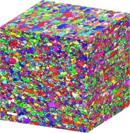
NATURE COMMUNICATIONS | https://doi.org/10.1038/s41467-020-16490-4                                                                         ARTICLE

               a                                            b                       c                            d
                                    Mixing & drying               RTA                   Hot-pressing                 Hot-rolling

                                                  H2O-EtOH
                                                 mixed solution

                Cu powders

                                                      Ar, H2

                   Sucrose

                                       Sucrose/Cu                  GLNs/Cu                    3D-GLNN/Cu-HP                3D-GLNN/Cu-HR

Fig. 1 Schematic illustration of overall fabrication processes. a The Cu powders were first coated with sucrose as a hybrid precursor. b The hybrid
precursor was then subjected to RTA process for growing GLNs. c The GLNs were interconnected into a continuous network structure in the Cu matrix by
using hot-pressing. d The fully-densified 3D-GLNN/Cu bulk composites were fabricated by hot-rolling.

Otherwise, if the RTA temperature rose to 900 °C, the Cu powders                difference attracted us to proceed to explore the formation
were severely sintered together and lost the powder character,                  mechanism of our continuous 3D-GLNN in the metal matrix.
which would be detrimental to the formation of GLNs (Supple-
mentary Fig. 1). Thanks to the ultrathin and intact layer of the
impregnated sucrose as the carbon source, the RTA-resulting                     Formation mechanism of 3D network structure. A fundamental
GLNs were identified with a uniform coating structure around Cu                  understanding of the formation mechanism of continuous 3D-
powders (Fig. 2b). The template-dependent morphology of GLNs                    GLNN in Cu is of vital importance to this ground-breaking
could be clearly spotted after etching Cu powders by FeCl3/HCl                  synthesis strategy. Results from initial experiments indicate that
solution (Fig. 2c). From the magnified image of the edge area in                 the formation of 3D-GLNN should be related to a special sheet
Fig. 2d and Supplementary Fig. 2, the GLNs demonstrate a few-                   welding mechanisms. To this end, we have carried out both
layered graphene-like feature, resulting in an ultralow loading                 experimental verification and modeling to identify the GLNs
content of GLNs of 0.096 wt. % (or 0.387 vol. %) in the GLNs/Cu                 welding phenomena as well as construct 3D-GLNN/Cu with
composite powders on the basis of C-S analysis. In the second                   optimized network architecture.
step, the continuous network of 3D-GLNN was in-situ con-                           During the hot-pressing process, parameters such as pressure,
structed during the hot-pressing process and the Cu matrix                      holding temperature would have great influence on the formation
composite was sintered and densified simultaneously. As shown in                 of the continuous network of 3D-GLNN. On one hand, the
Fig. 2e, it is apparent that an intact network structure of 3D-                 sufficient pressure and holding temperature could ensure the full
GLNN exposed after etching the superficial Cu matrix. The                        sintering of Cu powders in the Cu–Cu contact area. On the other
average pore size (0.5–2 μm) of the carbon skeleton matches well                hand, the densification achieved by the high pressure and high
with the particle size of Cu powder template. Furthermore,                      temperature could facilitate an intimate contact between the 3D-
Transmission electron microscope (TEM) image of Fig. 2f verifies                 GLNN and the adjacent Cu. In order to disclose this speculation,
that the carbon skeleton is a porous network structure constructed              a series of contrast experiments were conducted in which various
by the interconnected GLNs on the basal plane and forms Y-type                  samples with different synthesis parameters designated as “RTA
junction. The distinctive welding feature could be spotted in                   temperature-holding temperature-pressure” were prepared and
Fig. 2g from the cross-section view. Two adjacent GLNs with                     characterized. As shown in Fig. 3a, the results indicated that the
different lattice orientation, namely A and B, converged into one               800-800-50 sample possessed the most regular and homogenous
singe multi-layer GLNs (A + B) with uniform lattice orientation.                3D-GLNN structure. The magnified SEM image gave a strong
Taking advantage of the contrast difference between GLNs and                    evidence that the two GLNs were converged into a whole in the
copper in the second electron mode of SEM, a focused ion beam                   overlapping area. The continuous feature of 3D-GLNN was
(FIB) 3D reconstruction technique was performed and testified the                also confirmed from the Raman mapping image in Fig. 3g.
indeed formation of continuous 3D network architecture of GLNs                  Without exerting pressure, the loosely-packed GLNs/Cu sample
in the Cu matrix composites (Fig. 2h and Supplementary Movie 1                  (800-800-0) could not be sintered efficiently and only resulted in
and 2). In the final step, the hot-pressed 3D-GLNN/Cu bulk was                   a collapsed and layer-stacking structure of GLNs exposed on the
treated with a multi-step hot-rolling process for further densifi-               etched surface (Fig. 3b). The holding temperature is another
cation. The continuous network of 3D-GLNN remained intact                       sensitive parameter that dominates the sintering process by its
even after a severe rolling deformation of 70% reduction in                     influence on the diffusivity and plastic flow of Cu matrix. The low
thickness, verified by SEM images of the etched surface mor-                     holding temperature could not offer enough driving force for Cu
phology (Fig. 2i and j) and 3D reconstruction results (Fig. 2k and              powder to overcome the obstacles for sintering. Therefore, the
Supplementary Movie 3 and 4). It is known that for the                          800-400-50 sample which was hot-pressed under 400 °C had a
commonly-used 2D graphene derivatives RGO nanosheets, resi-                     poor densification and it only led to an irregular 3D-GLNN
dual oxygen-containing functional groups were inevitably pre-                   structure in copper (Fig. 3c). Further to say, the magnified SEM
served on the surface which make them undergo irreversible                      image suggests that only a small part of the overlapping area were
aggregation problems in mixing with Cu powders. As a result,                    welded together between layer A and B, thus it merely formed an
even under a similar sequence of preparation steps, it led to a non-            X-type contact in the junction area. From the point view of
uniform distribution of isolated RGO nanosheets with totally                    chemical structure, XPS is suitable for identifying the sp3 to sp2
different microstructure (Supplementary Note 1). The dramatic                   ratio and chemical bonds changes in the 3D-GLNN exposed on

NATURE COMMUNICATIONS | (2020)11:2775 | https://doi.org/10.1038/s41467-020-16490-4 | www.nature.com/naturecommunications                          3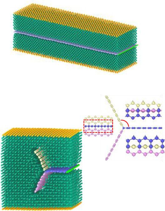
ARTICLE                                                                  NATURE COMMUNICATIONS | https://doi.org/10.1038/s41467-020-16490-4

       a                                              b                                              c                               d

                                                                       GLNs

                                                                                                                                     2-3 Ls

       e                                              f                              g               h

                                                                                      A

                                                                                              B

                                                                                            A+B

       i                                              j                                              k

                                      TD                                             ND

                                               RD                                             RD

Fig. 2 Characterizations of composite powders and bulk materials. a, b SEM image of the as-grown GLNs/Cu composite powders with a loosely-packed-
sphere structure (a) and the typical morphology of uniform GLNs coating structure around Cu powders (b) synthesized at 800 °C. Scale bar, 5 μm (a);
200 nm (b). c, d TEM image of GLNs after etching Cu powders (c) and the corresponding high-resolution TEM (HRTEM) image of the edge area (d), in
which the thickness of GLNs was determined as 2–3 layers. Scale bar, 200 nm (c); 2 nm (d). e, f SEM image (e) and TEM (f) image of 3D-GLNN after Cu
etching in the hot-pressed 3D-GLNN/Cu composites. Scale bar, 5 μm (e); 200 nm (f). g HRTEM image of the Y-type interconnection area of 3D-GLNN,
where the layer A and layer B merged into layer A + B. Scale bar, 5 nm. h, k Snapshot of FIB-3D reconstruction results of 3D-GLNN in the h hot-pressed
3D-GLNN/Cu (model size:3.85 × 2.14 × 2.00 μm) and k hot-rolled 3D-GLNN/Cu (model size:3.51 × 2.10 × 2.08 μm). i, j SEM images of 3D-GLNN after Cu
etching in the hot-rolled 3D-GLNN/Cu from i TD-RD plane and j ND-RD plane. Scale bar, 5 μm (i, j).

the surface of bulk materials. Generally, the deconvoluted C1s                existed between two adjacent layers in 400-800-50 samples. It is
peaks of GLNs could be fitted into four peaks: sp2 (284.6 eV), sp3             no doubt that this phenomenon suggested that the welding was
(285.1 eV), C–O (286.1 eV) and C=O (288.3 eV)23. The ratio of                 localized in a small part of the composites. By comparing the XPS
the composing bond types were calculated from the integrated                  result in Fig. 3e and Supplementary Fig. 4, the psp3 =psp2 ratio of
area of the fitted peaks (Supplementary Table 1). The significantly             GLNs in 400-RTA significantly decreased after hot-pressing.
increased psp3 =psp2 ratios of 800-800-0 (0.83) and 800-400-50                Meanwhile, the Raman results in Fig. 3f indicated that the
(14.3) compared to that of the RTA-800 composite powders                      structural disorder of carbon species, which could be determined
(0.19) indicated that the insufficient hot-pressing conditions                 by the ratio (ID/IG) between D band (1350 cm−1) and G band
caused structure damage to GLNs. To figure out whether the                     (1580 cm−1)24, also decreased after hot-pressing for 400-RTA
crystallinity of the in-situ grown carbon materials contributes to            composite powders. This could be strong evidence that structure
the formation of 3D-GLNN structure, we moved on to prepare                    healing occurs during the formation process of 3D-GLNN. And
bulk composites with low-temperature (400 °C) RTA-obtained                    not coincidentally, the Raman analysis result also demonstrated a
powders for comparison. The lower annealing temperature in                    similar structural healing during hot-pressing of RGO/Cu
RTA process led to an incomplete decomposition of sucrose and                 composite as the ID/IG ratio of the bulk decreased compared
thus a high ratio of amorphous carbon and residual oxygen                     that of RGO/Cu powders (Supplementary Fig. 5). According to
functional groups on the surface (Supplementary Fig. 4). From                 the analysis above, it is reasonable to suggest that the insufficient
Fig. 3d, it is interesting to note that the 400-800-50 sample                 driving force during hot-pressing in 800-800-0 and 800-400-50
exhibited a network structure analogy to that of 800-800-50                   samples could not overcome the obstacles for Cu densification,
sample. However, difference could be spotted in the magnified                  which hindered the structure healing process and failed to
image of the selected areas that the X-type contact junction                  construct an intimated bonding between adjacent GLNs. Instead,

4                 NATURE COMMUNICATIONS | (2020)11:2775 | https://doi.org/10.1038/s41467-020-16490-4 | www.nature.com/naturecommunications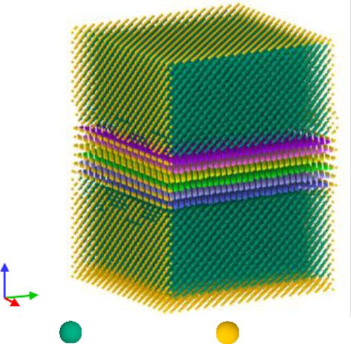
NATURE COMMUNICATIONS | https://doi.org/10.1038/s41467-020-16490-4 ARTICLE
a e f
Layer A 800-RTA
C1
Welding area
400-RTA
C4 C3 C2
Layer B 800-RTA
Intensity (a.u.)
800-800-50
800-800-50 C1
b 800-800-50
C4 C3 C2
Layer 800-800-0
Stacking
800-800-0
Intensity (a.u.)
800-400-50
C2
800-800-0 C1
C4 C3 400-800-50
c
800-400-50 500 1000 1500 2000 2500 3000
Layer A Layer B C3
C2 Raman shift (cm–1)
Welding area C4
C1 g 1.4E4
800-400-50
400-800-50
d Welding area
C1
C2
Layer B C4 C3
Layer A
292 290 288 286 284 282 280
400-800-50 Binding energy (eV)
0.4E4
Fig. 3 Sructure evolution during hot-pressing. a–d SEM images of the reinforcement morphology after etching the surface Cu layer in a 800-800-50,
b 800-800-0, c 800-400-50 and d 400-800-50. Scale bar, 1 μm for the left panel and 200 nm for the right panel (a–d). e, f Deconvoluted XPS C1s
spectrum and (f) Raman spectra of 3D-GLNN in the composite powders (400-RTA and 800-RTA) and bulks (800-800-50, 800-800-0, 800-400-50 and
400-800-50). g Surface Raman map of 800-800-50, the peak density of the 3D-GLNN G band (1580 cm−1) is imaged in red. Scale bar, 2 μm (g).
the sp2 structure of GLNs could be subjected to unexpected model as an example, the instantaneous peak thermal stress on the
damage due to the mechanical force or gas impurities absorbed in interface could exceeds 10 TPa for an 800 °C temperature gradient.
the gaps of Cu powders. In addition, by comparing the results It is no doubt that the enormous thermal stress which is dozens of
using Cu powders in different shapes and sizes (Supplementary times higher than the external press applied could cause a big
Figs. 6 and 7, and Supplementary Note 2), the successful impact on the embedded GNSs. In order to gain insights into the
construction of 3D-GLNN/Cu requires the Cu powders to be in effect of Cu matrix on the welding process of GLN layers, it is
regular spherical shape and have relatively small size to facilitate particularly insightful to examine the evolution of the micro-
partial sintering between Cu powders during GLNs synthesis and structure of GLNs embedded in the copper matrix. The molecular
thus form the interpenetrating graphene-like network structure dynamics (MD) simulations were conducted based on a simplified
afterward. structural model consisted of two 3-layer graphene/copper matrix
The matrix effect could be another important factor for the (3LGs/Cu) countering parts with face-to-face contact, as depicted in
formation of an interconnected graphene network architecture. Fig. 4a. The initial space between the two top graphene layers was
The high CTEs of metallic materials endow them with high set as 3.35 Å to mimick the contact feature in the hot-pressing
thermal-elastic properties, which dramatically influence the synth- process under sufficient pressure and temperature. To approach the
esis and phase transformation process25. It is well recognized that real structure of GLNs in the experiments, the graphene layers were
the huge gap of CTEs between the matrix and the reinforcement designed into an imperfect structure with a defect concentration of
could cause high internal stress in the composites during the rapid 0.5 at. % by artificial creating single-atom vacancies on the surface
cooling after hot processing. As previously confirmed, it may result (Supplementary Fig. 9a). Besides, to facilitate the observation of the
in massive geometric necessary dislocations (GNDs) accumulated interaction between Cu and graphene on the interface, we fixed
on the interface and thus strengthen the materials26. However, rare the borders of the model in the Z and Y direction and imposed the
studies have been focused on the interaction between reinforce- periodic boundary condition in the X direction. The structure of the
ment and the matrix considering the thermal stress effect during model relaxed to thermal equilibrium under NVT ensemble at
the high-temperature processing. Based on the thermal-elastic 1293 K was verified with good stability. The simulation results
mechanism, the peak thermal stress (σth) of the 2D film-substrate under different loading temperature at 493 K, 693 K, 893 K, and
model could be calculated as,27 1093 K were demonstrated in Fig. 4b. A downward trend of the
Ec distance between graphene layers could be observed with
σ th ¼ ðα αc ÞðT T0 Þ ð1Þ the increase of the loading temperature, which is caused by the
1υ s expansion-induced thermal stress of Cu matrix. To visualize the
where Ec and υ are the elastic modulus and the Poisson ratio of the bonding conditions at different temperatures, a lower-limit length
film, respectively. αs and αc each represents the CTE of the substrate of the formation of covalent-like bonds were set as 2.80 Å. It is well-
and film. T–T0 is the temperature gradient. Taking Cu–Gr/Gr–Cu known that the interlayer binding energy increased as the distance
NATURE COMMUNICATIONS | (2020)11:2775 | https://doi.org/10.1038/s41467-020-16490-4 | www.nature.com/naturecommunications 5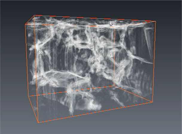
ARTICLE NATURE COMMUNICATIONS | https://doi.org/10.1038/s41467-020-16490-4
a b TPa
90 90 90 90 0.00
80 80 80 80 –0.19
70 70 70 70 –0.38
60 60 60 60 –0.56
3LGs/Cu
Z (Å)
Z (Å)
Z (Å)
Z (Å)
50 50 50 50
–0.75
40 40 40 40
–0.94
30 30 30 30
6LGs 20 20 20 20 –1.13
10 10 10 10 –1.31
493 K 693 K 1093 K
3LGs/Cu 0 0 0 893 K
0 –1.50
10 20 30 40 50 60 70 10 20 30 40 50 60 70 10 20 30 40 50 60 70 10 20 30 40 50 60 70
z Y (Å) Y (Å) Y (Å) Y (Å)
y
x
Copper atoms Fixed atoms
c d e 125
293 K
104 293 K
104 6LGs/Cu
693 K 693 K
6LGs
893 K 893 K
100
3 3 1093 K
10 1093 K 10
1293 K
Stress (MPa)
1293 K
1LG pull-out from 6LGs/Cu
Counts
Counts
75
102 102
50 1LG pull-out from 6LGs
101 101
25
100 100
2.40 2.60 2.80 3.00 3.20 3.40 2.40 2.60 2.80 3.00 3.20 3.40 200 400 600 800 1000 1200 1400
Bond length (Å) Bond length (Å) Temperature (K)
Fig. 4 MD simulations of welding between graphene-like nanosheets. a Atomic configuration of two face-to-face contact 3LGs/Cu (6LGs/Cu).
b Simulation results illustrating the color Z-direction stress maps of Y–Z single-layer slice in the middle of 6LGs/Cu and the formation of covalent-like
bonds between graphene layers at 493 K, 693 K, 897 K, and 1093 K. c, d The bonding length statistics at different simulated temperatures of (c) 6LGs and
(d) 6LGs/Cu models. e The 1LG pull-out stress versus temperature plots for 6LGs and 6LGs/Cu. Source data are provided as a Source data file.
between graphene layers decreased to a certain level28. As revealed temperatures were plotted in Fig. 4e. It is demonstrated that the
from the result, intuitively the number of carbon atoms connected pull-out strength increased with the loading temperature rising
by the covalent-like π−π bonding between adjacent layers increased above 693 K, demonstrating an enhanced adhesion strength
with the rising temperature in 6LGs/Cu, suggesting an enhanced between graphene layers. The pull-out stress between models with
welding feature between graphene layers (Fig. 4b). Quantitatively, or without copper were further compared. It proved that under the
the number of inter-layer bonds with bond length of 2.5–3.4 Å were low temperature of 293 K and 693 K, the ultimate strength of the
counted for both 6LGs/Cu and 6LGs without Cu matrix. A models were almost equal due to the inappreciable contribution of
significant increase in the total numbers of inter-layer bonds below thermal stress to the adhesion between adjacent graphene layers.
3.4 Å as well as the number of short-distance bonds could be found While the pull-out strength exhibited much higher values for the
in 6LGs/Cu compared with those of 6LGs, respectively (Fig. 4c and models with Cu than those without Cu at a higher temperature of
d). What’s more, the detailed microstructure evolution proved that 1093 K and 1293 K. Therefore, the above results validate that the
during the simulation a structural rearrangement occurred for the thermal stress during hot-pressing undoubtedly has a significant
atoms near the defects in the graphene layers (Supplementary effect on the welding between the graphene layers.
Fig. 10). In the previous study reported by Liu et al.29, the welding Based on the analysis above, the formation of 3D-GLNN is
between graphene layers required a high driving force provided by made possible by synergy between appropriate hot-pressing
the high loading temperature of more than 1200 °C. While in this parameters and the Cu matrix effect. A sufficiently high level of
study, the thermal stress caused by the large gaps of CTEs between hot-pressing pressure and holding temperature guarantee that the
Cu and graphene promoted the compaction of graphene layers and in-situ grown GLNs are embedded in the grain boundaries of
resulted in the covalent-like π−π bonding of interlayer carbon densified Cu matrix and reach an effective distance for
atoms at a relatively lower temperature. The thermal stress on the interaction. Thus, 3D-GLNN forms by the thermal-stress induced
graphene-Cu interface increased linearly with the rise of tempera- sheet welding between GLNs at high temperatures.
ture, and thus it resulted in the rising numbers of covalently-
bonded carbon atoms (Supplementary Fig. 8). Without Cu, few
carbon atoms with covalent-like bonds could be observed even Composite microstructure characterization. The continuous 3D
under a high loading temperature of 1293 K. It should be pointed graphene network architecture has a significant impact on the
out that, negligible difference was observed between the inter-layer multi-scale microstructure of the copper matrix. Macroscopically,
bonding conditions of different defect concentration levels (0.5 at.%, the average copper grain size was limited to a small value of 1.9
1.0 at.%, and 2.0 at.%) in 6LGs/Cu model (Supplementary Fig. 9b), μm (Supplementary Fig. 11d) due to the grain constraint of 3D-
which implies that the bonding trend is not drive by defects at a GLNN after hot-pressing, while conspicuous grain growth effect
relatively low defect level. Next, we performed graphene pull-out (average grain size of 18.2 μm) was identified in the pure Cu
simulations to compare the adhesion strength between graphene matrix (Supplementary Fig. 11a–c). The grain structure main-
layers of the aforementioned models relaxed under different loading tained well with no obvious texture after multi-step hot-rolling as
temperatures. The average pull-out stress-displacement at different confirmed by the Electron back-scattered diffraction (EBSD)
6 NATURE COMMUNICATIONS | (2020)11:2775 | https://doi.org/10.1038/s41467-020-16490-4 | www.nature.com/naturecommunications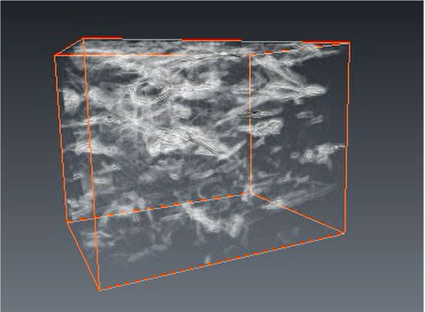
NATURE COMMUNICATIONS | https://doi.org/10.1038/s41467-020-16490-4 ARTICLE
a b c d
Ns
r GL
Cu
Cu
e
tilay
Cu
Mu l
ND
RD TD
e 350 f g
3D-GLNN/Cu composite Pure Cu
319 RGO/Cu
300 80.4
292 35 3D-GLNN/Cu
100 G-network
Strenthening efficiency
250 240
RGO/Cu composite 25 65.2
Stress (MPa)
200 188
202
150 Pure Cu
117 CNT-lamellar
13
100 G-lamellar
30.3
10
50 G-homogenous
CNT-homogenous
0
Yield strength Tensile strength Elongation Toughness
0.00 0.05 0.10 0.15 0.20 0.25 0.30 0.35 0.40 (MPa) (MPa) (%) (MJ m–3)
0 20 40 60 80 100 120
Strain (mm/mm) Retension of elongation (%)
h i j
450
Pure Cu
TC enhancement efficiency, η (%)
Thermal conductivity (W m–1K–1)
Thermal conductivity (W m–1K–1)
440 RGO/Cu
25
3D-GLNs/Cu G-network
420 413 e–
400 407 20 e–
e–
400 394 e–
378377
15 G-aligned e–
380 375
350 G-homogenous 3D-GLNN
362
360 10
348 349 CNT-aligned e- Cu
300 Pure Cu 340 5
324322 325 G-laminate
RGO/Cu
320 GR-aligned
3D-GLNN/Cu 0
CNT-homogenous
250 300
0 100 200 300 400 25°C, # 25°C, ⊥ 300°C, # 300°C, ⊥ 0 10 20 30 40 50 60
Temperature (°C) Reinforcement content (vol. %)
Fig. 5 Typical microstructures and performance. a EBSD micrographs of hot-rolled 3D-GLNN/Cu from three orthogonal directions. Scale bar, 5 μm.
b Bright-field TEM image of the 3D-GLNN/Cu composites. Scale bar, 500 nm. c, d Bright-field scanning transmission electron microscope (STEM) image of
the 3D-GLNN/Cu composites (c) and the corresponding HRTEM image taken near the grain boundaries of the composite (d). Scale bar, 200 nm (c); 5 nm
(d). e Tensile stress-strain curves of pure Cu, RGO/Cu, and 3D-GLNN/Cu. f Comparative bar chart of mechanical properties of pure Cu, RGO/Cu, and 3D-
GLNN/Cu. g Retention of fractural elongation versus strengthening efficiency of tensile strength plot, showing that the as-prepared 3D-GLNN/Cu
composite had an outstanding combination of strengthening efficiency and ductility. h The in-plane thermal conductivities of pure Cu, RGO/Cu, and 3D-
GLNN/Cu. i Comparative bar chart of thermal conductivities of pure Cu, RGO/Cu, and 3D-GLNN/Cu at room temperature (25 °C) and 300 °C. j TC
enhancement efficiency versus graphene content plot, demonstrating a high enhancement efficiency of 3D-GLNN in thermal conductivity at a relatively
small graphene content compared with other reported nanocarbon reinforced Cu matrix composites. Inset is the illustration of the electrons and phonons
transfer channels in 3D-GLNN and the reduction of electrons scattering in the Cu matrix near the interface.
analysis from three inter-perpendicular orientations (Fig. 5a and majority of Cu grains with high Taylor factors could be spotted in
Supplementary Fig. 11e, f). In combination with the morphology hot-rolled RGO/Cu from Supplementary Fig. 12b, indicating that
characterization of 3D-GLNN in the Cu bulks in Fig. 2e, h–k, the plastic deformation is hard to be started in the material. While in
result confirms that 3D-GLNN is a flexible network, which could hot-rolled 3D-GLNN/Cu the grains with high Taylor factors
deform simultaneously with the matrix and keep bound to the dispersed more homogenously in the matrix, suggesting a much
matrix grains. In contrast, the RGO nanosheets, failed to hinder smaller resistance for plastic deformation. On the microscopic
the matrix grains effectively during hot-rolling due to the lim- level, The Y-type junction feature shown in Fig. 5b, c and Sup-
itation of its 2D shape and relatively small size (Supplementary plementary Fig. 13 is consistent with the TEM image in Fig. 1g,
Fig. 12a). The Talyor factor maps of the EBSD results were also proving that the 3D network-shaped of 3D-GLNN distribute
provided in Supplementary Fig. 12b and c. Taylor factor is an along the grain boundaries. From the HRTEM image of Fig. 5d,
important factor for evaluating the deformability of polycrystal- the multi-layer structure obtained from the welding of the adja-
line grains, which is a function of the grain orientation and the cent GLNs layers could be identified. In comparison, RGO were
external deformation types. The larger Taylor factor values, characterized with an isolated island-like distribution feature in
the more plastic work needed for plastic deformation due to the the hot-rolled samples (Supplementary Fig. 14). Dislocation for-
increased obstacles for the movement of more slip systems30. A ests could be observed near the graphene/Cu interfaces in both
NATURE COMMUNICATIONS | (2020)11:2775 | https://doi.org/10.1038/s41467-020-16490-4 | www.nature.com/naturecommunications 7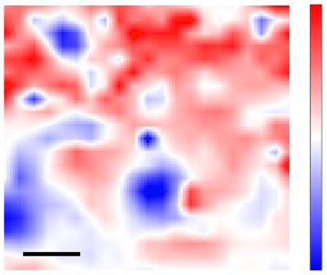
ARTICLE                                                                 NATURE COMMUNICATIONS | https://doi.org/10.1038/s41467-020-16490-4

samples, which gave an evidence of dislocation pinning effect of             GLNN/Cu composite has higher room-temperature in-plane TD
graphene31.                                                                  value of 112.706 mm2 s−1 than that of RGO/Cu (109.447 mm2 s−1)
                                                                             and pure Cu (107.082 mm2 s−1). The higher TD value indicates
Mechanical performance. Figure 5e demonstrates the tensile                   that the 3D-GLNN/Cu is more capable in conducting thermal
response of the pure Cu matrix, 3D-GLNN/Cu, and RGO/Cu                       energy than RGO/Cu and pure Cu. Excluded the negative grain-
composites, where the tensile direction was parallel to the rolling          size effect32, the macroscale enhancement of the thermal
direction (the detailed process of the tensile deformation process           conductivity in a 3D-GLNN/Cu bulk composite can be mainly
was discussed in Supplementary Note 3 and Supplementary                      attributed to the network architecture and continuity of graphene
Fig. 15). Encouragingly, 3D-GLNN/Cu delivers a yield strength                in the copper matrix. Notably, 3D-GLNN/Cu bulk composite has
(YS) of 292 ± 21 MPa, an ultimate tensile strength (UTS) of 319 ±            an interpenetrated network, suggesting the electron heat transfer of
30 MPa, which was markedly superior to pure Cu matrix (YS:                   copper remains intact. In addition, the network architecture
117 ± 14 MPa, UTS: 202 ± 15 MPa). Besides, the fractural elon-               composed by graphene stitched to each other covalently provides
gation (FE) of 3D-GLNN/Cu was measured as 25.4 ± 5.6%, which                 much more channels for phonons to transfer even at a small
is only 27% reduction compared with pure Cu. Therefore, the                  graphene content of 0.387 vol. %. While for the RGO/Cu, the
combination of a high UTS and a moderate FE of 3D-GLNN/Cu                    irreversible aggregation problem could reduce the effective volume
resulted in a 23% increase in toughness (measured by integration             fraction of RGO nanosheets and the high heat resistance caused by
of the area under the stress/strain curve) than pure Cu. What’s              sheet-overlapping degraded the TC value enhancement efficiency
more, the tensile response of 3D-GLNN/Cu also exhibits a sub-                dramatically. The conclusion above could also be verified from the
stantial improvement in the strength (YS and UTS) and TE over                measured TC values of the aforementioned samples in the
RGO/Cu. The toughness calculated of 3D-GLNN/Cu is more                       direction perpendicular to the rolling plane (through-plane TCs,
than 1.5 times higher than that of RGO/Cu (Fig. 5f). Up to now, a            K⊥) (Fig. 5i). It demonstrates that 3D-GLNN/Cu has a lower K⊥
large number of nanocarbon (CNTs and graphene) reinforced                    value of 375 W m−1 K−1 than pure Cu (394 W m−1 K−1) at the
MMCs have verified the strengthening potential of these nano-                 room temperature. However, the value of TC at 300 °C for the
sized reinforcements. To directly evaluate and compare the                   composite decreased to 349 W m−1 K−1, equaling the value of pure
mechanical performance of these materials, we summarized the                 Cu (350 W m−1 K−1). Generally, the rising temperature increases
data reported by various research groups on the strengthening                the probability of electron scattering at the grain boundaries in the
efficiency of UTS ðRσ ¼ σ UTSfðCÞσ      UTS ðMÞ
                                                Þ and retention of FE        matrix33. In this study, the thermal conductivity decreased mainly
                                 σ UTS ðMÞ                                   due to the complex interplay of both the intrinsic and boundary
(Supplementary Table 2) as plotted the scatter diagram in Fig. 5g.           scattering mechanisms of copper. Thanks to the distribution of 3D-
Thanks to the unique continuous network architecture, 3D-                    GLNN in the grain boundaries, a reduced grain boundary
GLNN/Cu obtained a high strengthening efficiency of 149.7 with                scattering for electrons as well as surface scattering of electrons
a low volume fraction of 0.387 vol. % 3D-GLNN. What could be                 and phonons could be achieved in 3D-GLNN/Cu at elevated
observed from the figure is that for most cases of the trade-off              temperatures33,34. What’s more, by comparing the measurement
correlation between the two parameters still exist in composites             results of 3D-GLNN/Cu and RGO/Cu, significant increase in both
with homogenous and lamellar architecture. Remarkably, the 3D-               of the in-plane and through-plane TC values could be obtained in
GLNN/Cu in this study outperformed most other nanocarbon                     3D-GLNN/Cu at different elevated temperatures, which serves as
reinforced MMCs in terms of the combination of strengthening                 strong evidence of the successful construction of a heat conducting
efficiency and ductility, far outside the domains enclosing the               network by 3D-GLNN in the Cu matrix. Meanwhile, the flexible
data for different architecture types reported in the literature (red        feature of the network composed by nanoscale reinforcements
star mark in Fig. 5g).                                                       resulted in a slight reduction in CTE of the bulk composites,
                                                                             compared with pure Cu and RGO/Cu (Supplementary Fig. 17).
Thermal and electrical conductivity. Figure 5h shows the ther-               Similarly, we defined the TC enhancement efficiency (η ¼
mal conductivities (TCs) of pure Cu, RGO/Cu, and 3D-GLNN/Cu                  KC KM
composites parallel to the rolling direction (in-plane TCs, K||). The        fKM 100 ´ 100%) to evaluate the enhancement in the in-plane TC

TC of 3D-GLNN/Cu reached 413 W m−1 K−1 at room tempera-                      per volume fraction. By putting together the η versus f data of
ture which exceeded that of pure Cu (378 W m−1 K−1) and                      copper matrix composites reinforced by naonocarbon materials
decreased slightly to 407 W m−1 K−1 at 300 °C. While a significant            (typically CNTs and graphene) from the reported papers and this
decline trend could be observed in the TC values of pure Cu as               work, it is clear to see that the 3D-GLNN/Cu with network
temperature rose from room temperature to 400 °C. A similar                  architecture has the highest η at a relatively small reinforcement
decreasing trend could be observed form the curve of RGO/Cu                  content (Fig. 5j and Supplementary Table 4). At the same time,
composite. The discontinuous RGO distribution resulted in lower              the ratio between K|| and K⊥ (K||/K⊥) of 3D-GLNN/Cu (0.91)
TC values compared with those of pure Cu in the temperature                  at room temperature is much higher than the values of copper
range of 25–300 °C. The high-temperature thermal conductivity is             matrix composites with alignment or laminate architecture. It
more valuable for reference in considering the actual hot-wall               suggests that network architecture also benefits to modify the
contact condition for using copper related materials as heat                 anisotropy in thermal conductivity as well. Additionally, the
transfer. Experimentally, the TC values (K) were determined by               electrical conductivity (EC) was measured as 60.0 ± 0.5 MS m−1,
parameters of their thermal diffusivities (TD, α), specific heat (Cp)         much higher than that of pure Cu (58.5 ± 0.5 MS m−1) and RGO/
and density (ρ) values, as shown in Eq. (2)32:                               Cu (55 ± 1.0 MS m−1). It is unanticipated to discover that this EC
                                                                             value even exceeds 3.4% of the International Annealed Copper
                              K ¼ αCp ρ                               ð2Þ    Standard (IACS) (58.0 MS m−1). The high EC of 3D-GLNN/Cu
                                                                             provided tangible evidence of the successful construction of the
  Accordingly, TD is the determining factor for the TC value of a            continuous electron pathway provided by the coupling between
particular bulk material as the value of density and specific heat            3D-GLNN and Cu35. Moreover, based on the electron-transfer-
were almost unchanged with the increase of temperature                       related Widemann-Franz law K/σ = LT32,36, where σ is the EC and
(Supplementary Table 3). The in-plane TDs versus temperature                 L ¼ ðπ2 =3ÞðkB =qÞ2  2:44 ´ 108 WΩK2 is the Lorenz number,
data were plotted in Supplementary Fig. 16. It confirms that 3D-              the predicted TC could explain 94% of the total measured value. It

8                NATURE COMMUNICATIONS | (2020)11:2775 | https://doi.org/10.1038/s41467-020-16490-4 | www.nature.com/naturecommunications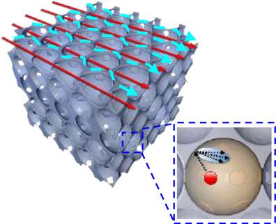
NATURE COMMUNICATIONS | https://doi.org/10.1038/s41467-020-16490-4                                                                    ARTICLE

confirms that the interconnected Cu matrix still acts as the                     stress. One single-layer graphene embedded in 13 layers of Cu on
dominant role in deciding the TC and EC of the composites at                    both sides was built to study the pull-out process of graphene in
room-temperature.                                                               2D-G/Cu (Fig. 6g). At the same time, a regular three-dimensional
                                                                                network composed of single-layer graphene with an all-sp2 struc-
                                                                                ture was built inside Cu matrix to study the interfacial behavior of
Discussion                                                                      3D-G/Cu (Fig. 6h). The total numbers of the carbon atoms in the
In the previous research on polymer/ceramic matrix composites                   two models were controlled to be same. The pull-out force/energy-
reinforced by 3D graphene, the achievement of a high strength                   displacement curves of 2D-G/Cu and 3D-G/Cu were presented in
and a high toughness have been commonly reported5,10,37.                        Fig. 6i, j, respectively. A steady pull-out progress could be verified
However, this phenomenon is not well understood and has been                    from the relatively smooth curves shape in 2D-G/Cu (Fig. 6i). The
attributed to the network architecture of which toughening is                   structure of 2D graphene was almost unchanged after the full pull-
interpreted by the crack blocking effect, namely crack bridging                 out from copper. While, things became much more complicated
and crack deflection. While in this kind of materials, strengthening             for the case of 3D-G/Cu (Supplementary Movie 5). According to
is generally interpreted by the simplified load transfer effect                  the trend of total energy-displacement curve, the whole progress
between 2D graphene and the polymer/ceramic matrix. The                         could be divided into three steps. The snapshots of the typical state
interfacial deformation behaviors, which microscopically dom-                   A-D were presented in Fig. 6k. In the Stage 1 (0–4.1 Å), 3D-G was
inate the interaction between 3D graphene and the matrix, were                  pulled out smoothly with little deformation which could be
rarely studied. In particular, for metallic materials which are                 reflected by the linear increase of the total energy during this
capable of better deformation ductility than polymers and cera-                 period. Besides, the copper matrix deformed elastically; In the Stage
mics, the micro-scale interfacial behaviors could be the key roles in           2 (4.1 Å–12.7 Å), 3D-G was deformed by the resistance force of Cu
the overall mechanical performance. Experimentally, the inter-                  matrix during the on-going pull-out displacement. The complex
facial shear stress derived from the simplified shear-lag model for              interaction between Cu and 3D-G induced energy fluctuation in
3D-GLNN/Cu was estimated as 86.0 MPa, while that of 2D-RGO/                     the total energy and thus resulted in a violent rise and fall for the
Cu was calculated as 26.4 MPa (Supplementary Note 4). The result                pull-out force. Plastic deformation could be observed in the copper
suggests that different interfacial deformation mechanisms should               matrix and the dislocation density increased sharply (Supplemen-
exist in the two systems. To deeply understand the interfacial                  tary Fig. 24); In the Stage 3 (>12.7 Å), the 3D-G deformed into a
deformation behaviors of 3D graphene in the composites, in situ                 planar structure and lost the effective interaction with the Cu
SEM tensile test were performed in comparisons with 2D gra-                     matrix. The total energy of 3D-G decreased due to the instability of
phene/Cu. During the test, dynamic observation of the whole                     the deformed 3D-G model and resulted in a negative value of pull-
cracking process could be performed on the dog-bone samples                     out stress of this range. The on-going plastic deformation of copper
preprocessed with a notch (Supplementary Fig. 18). Figure 6a                    matrix further increased the dislocation to a high level of 14.3 ×
presents the load-displacement curves of 3D-GLNN/Cu and                         1014 m−2, suggesting a high dislocation strengthening capability of
RGO/Cu with several interrupted stages. The SEM capturing of                    3D-G. With the same displacement of 12.7 Å, the increased
the crack evolution of the stages (I–VII) of 3D-GLNN/Cu and                     potential energy correlated to the work done by the pull-out force
(A-D) of RGO/Cu in Fig. 6a was shown in Supplementary Fig. 19                   was measured as 164 eV for 3D-G/Cu model, which is one times
and 22, respectively. During the early stage of loading, the                    more than that of 2D-G/Cu (79 eV). To compare the difference in
microcracks initiated from the pre-made notch propagated slowly                 the interfacial behaviors between 3D-G/Cu and 2D-G/Cu, it is
until reaching the stage near the yield strength point (III) for 3D-            important to convert the measured data into a unified physical
GLNN/Cu (Supplementary Fig. 20) and (B) for RGO/Cu (Sup-                        quantity. Herein, we proposed to use the interfacial shear stress (τ),
plementary Fig. 22b). After that, the crack propagated steadily                 which was estimated by the division of the average pull-out force
until the final fracture of the samples. It is found that the 3D-                (Fpm) with the projected area (A) in the X–Y plane given as40:
GLNN/Cu has a higher tensile strength as well as a longer elon-                                                  Fpm Fpm
gation compared with those of RGO/Cu, suggesting a good frac-                                                τ¼      ¼                            ð3Þ
ture tolerance capability. The capturing of the two composites                                                   2A     2wL
after the final fracture are shown in Fig. 6b, c. The result reveals             where w is the width of graphene (46.85 Å), L is the projected
that only one principle crack extended through the sample with no               length of graphene. The average pull-out force for 2D-G/Cu was
obvious secondary cracks, indicating that ductile fracture hap-                 determined as 10.6 nN and the corresponding interfacial shear
pened in both composites38. During the propagation process, it is               strength was calculated as 69.7 MPa for the whole progress. Com-
hard to spot RGO nanosheets on the side position of cracks due to               paratively, the average pull-out force for the periods with increased
their random distribution in the matrix. Besides, it turned out that            total energy (Stage 1 and Stage 2) was estimated as 22.7 nN and the
RGO nanosheets were peeled off from the matrix based on the                     interfacial shear strength was obtained as 214.8 MPa, almost two
SEM images in Fig. 6d and Supplementary Fig. 23. It tells a dif-                times higher than that of 2D-G/Cu. If we focused on the steady
ferent story for the crack propagation process of 3D-GLNN/Cu.                   pull-out stage (Stage 1), the pull-out force was measured as 28.5 nN
Crack bridging by graphene/Cu interlocked structure (Fig. 6e) as                and resulted in a high interfacial shear strength of 269.7 MPa, more
well as 3D-GLNN (Fig. 6f and Supplementary Fig. 21) were                        than 2.8 times higher than that of 2D-G/Cu. Coincidently, both the
captured in the stage (IV) and (V). The difference in the cracking              theoretical and experimental results pointed to a similar three-times
morphology could be attributed to the different load transfer                   relationship between 3D-GLNN/Cu and 2D-RGO/Cu. The simu-
capabilities between 3D-GLNN/Cu and RGO/Cu. Benefited from                       lation results strongly verified that, compared with 2D graphene/
the interlocking network structure, the 3D-GLNN bridged                         Cu, the dramatically increased interfacial shear strength which
between the cracked matrixes postpones the extending progress of                contributes to a better load transfer is the main cause of the
cracks5,37. To achieve effective interaction with cracks, the geo-              enhancement in mechanical strength for 3D graphene/Cu.
metric size of the reinforcement should be large enough to match                   Based on the above results, the superior mechanical properties of
the crack size39. In this sense, 3D-GLNN interconnected by                      3D-GLNN/Cu could be attributed to the unique network archi-
thousands of GLNs, enlarged the effective size to react with cracks.            tecture: First, the continuous 3D-GLNN restricted the growth of
   We then applied MD simulations on two simplified models to                    matrix grains and resulted in grain refinement strengthening
study the effect of network architecture on the interfacial shear               mechanism; second, the network architecture brought thousands of

NATURE COMMUNICATIONS | (2020)11:2775 | https://doi.org/10.1038/s41467-020-16490-4 | www.nature.com/naturecommunications                            9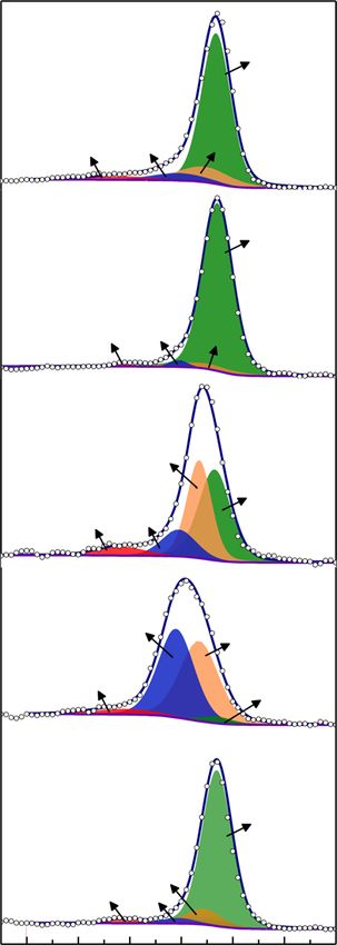
ARTICLE NATURE COMMUNICATIONS | https://doi.org/10.1038/s41467-020-16490-4
a 900 b d f
800
(B)
700 (III) 3D-GLNN/Cu Peel-off
RGO
600
(IV)
Load (N)
500 (V)
Fractured
400 RGO/Cu 3D-GLNN
300 RGO/Cu (C) c e
200 (II) (VI)
100
(A) (I) (D) (VII)
0 Crack
0 200 400 600 800 1000 bridging
Displacement (μm) 3D-GLNN/Cu
g Fixed i 16
j 70
Total energy Total energy
60 C D –4.040
14 Pullout force –1.240 Pull-out force
12 50 B –4.044
Energy×10–4 (eV)
Energy×10–5(eV)
10 40
Force (nN)
Force (nN)
–1.244
8 –4.048
2D-G 30
Z 6
Loading 20 –4.052
4 –1.248
10
Y X 2 A
Fixed –4.056
0 0
2D graphene pull-out Stage 1 Stage 2 Stage 3
–2 –1.252 –10 –4.060
h Fixed sp2 0 20 40 60 80 100 120 140 160 180 0 2 4 6 8 10 12 14 16
120° Displacement (Å) Displacement (Å)
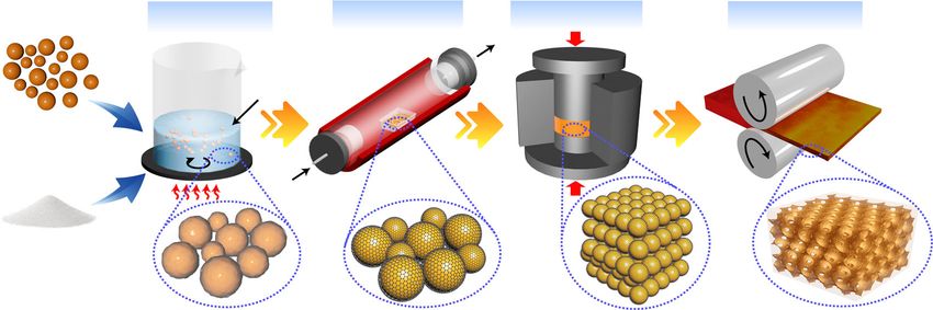
k Slip band
A B formation C D
Loading
Z
3D-G
Y X
Fixed
Fig. 6 Comparison between 3D graphene/Cu and 2D graphene/Cu. a Load-displacement curves of RGO/Cu and 3D-GLNN/Cu with several paused
stages. b, c SEM images of tensile samples after in-situ tensile test of (b) RGO/Cu and (c) 3D-GLNN/Cu. Scale bar, 1 mm (b, c). d Typical SEM image of
RGO peeled-off from the matrix in stage (C) during tensile deformation. Scale bar, 5 μm. e, f Typical SEM images of crack bridging by e graphene/Cu
interlocked structure and f 3D-GLNN. Scale bar, 2 μm (e, f). g, h Atomic configurations in MD simulations of g 2D-G/Cu and h 3D-G/Cu, 3D-G was built
with an all-sp2 structure at an angle of 120 degree between three directions. i, j The simulated pull-out force-displacement curves of i 2D-G/Cu and j 3D-
G/Cu, the 2D-G was pulled out steadily until fully separated from the matrix while 3D-G was deformed with a complicated progress which could be divided
into 3 stages. k Typical snapshots corresponding to the point A-D during the deformation progress of 3D-G/Cu. 3D-G was blocked by the Cu matrix, the
two wings of which were constrained parallel to the X–Y plane in D. The atoms in red indicated HCP transition formed on the {111} plane. The dislocation in
magenta and blue are attributed to 1/6 (Shockley) dislocation and 1/6 (Stair-rod) dislocation, respectively.
interfaces in the matrix, which blocked dislocations from moving level. Based on the average ID/IG ratio of about 0.75 (Supple-
across the grain boundaries efficiently; Last but not the least, the mentary Fig. 25), the density of defects in graphene, ND, could be
3D geometric feature of 3D-GLNN improved the interfacial shear estimated by the following equation43:
stress and thus benefited a better load transfer strengthening
2 ð1:85 ± 0:5Þ ´ 1022 ID
mechanism. It should be stressed that the 2D graphene usually has ND ðcm Þ ¼ ð4Þ
a low interfacial shear stress in the composites due to the wrinkling λ4 IG
of GNSs41. So the interfacial shear stress was much smaller than where λ represents the laser wave length (532 nm). The ND value
the theoretical estimation and the common interfacial failure of 3D-GLNN is calculated to be 16.8 ± 4.7 × 1010 cm−2. Thus the
mechanism for 2D graphene/metal is interfacial sliding followed by TC of 3D-GLNN could be predicted as about 450–500 W m−1 K−1
graphene pull-out, in which case graphene could not give full play based on the experimental work by Malekpour et al.44. In view of
to its outstanding mechanical properties42. The graphene network the similar continuous and multi-layer feature of graphene, this
architecture, taking advantages of the interlocking behaviors value matches well with the reported data of graphene film/Cu
between the matrix and the reinforcement, offers a new strategy to system (445–538 W m−1 K−1)45–47. Restricted by the annealing
break through the limitations. From another point of view, the temperature of 800 °C in the RTA step, the crystallinity and the
network architecture also enlarged the effective size of graphene intrinsic TC value of GLNs still have much room for improvement
into micrometer level, which equaled to the actual crack length and on the condition that an optimized GLNs growth procedures, such
induced extrinsic toughening mechanisms such as crack bridging. as plasma-enhanced chemical vapor deposition, could be achieved.
For the thermal transportation properties, the intrinsic TC of Extrinsically, different from homogenous distribution and align-
the reinforcement and extrinsic interface and architecture effect ment architecture of GNSs, a continuous network structure may
are both the key factors. Given the technical difficulty for accurate reduce both the Kapitza resistance and graphene-graphene contact
measurement of TC of 3D-GLNN in the copper matrix, herein an resistance to a minimized level within the covalently bonded
approximate value could be predicted according to the compar- networks48. At the same time, the interconnected network struc-
ison with the reported work on graphene with the same defect ture of graphene/Cu provided extra electrons and phonons transfer
10 NATURE COMMUNICATIONS | (2020)11:2775 | https://doi.org/10.1038/s41467-020-16490-4 | www.nature.com/naturecommunicationsYou can also read